Assignment 6-Frontal Crash Simulation Challenge
AIM: To test the vehicle crashworthiness by performing a frontal crash analysis allowing the vehicle to crash into a rigid wall and extracting the results using RADIOSS
We will be discussing this project as 2 segments i.e, theary and procedure
PROCEDURE:
These are the steps to be followed after importing the model so as to make it ready for the crash analysis
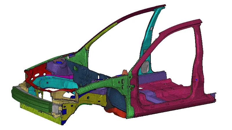
- import the model from the solver deck and under stand the model component wise , and check the critical region components
- change it from the grid view
1.UNITS CHECK:
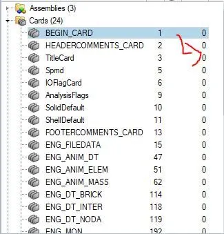
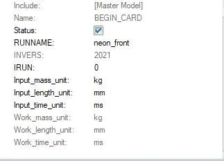
- Check the unit system because we should have to know the preset units
- MODEL>>CARDS>>>BEGUIN>> check in the command area
2.CREATING THE INTERFERENCE:
- Inteference is the nothing but th typeof contact that we are establishing between the interacting surfaces
- this defines the behaviour of the intracting parts by indentifing them as slave and master
- GROUPS>delete the unnecessary contacts if there are any>>CREATE
- card image>>TYPE 7>> set the master and slave
- give all the 74 COMPONENTS as we are mkinf the whole crash analysis
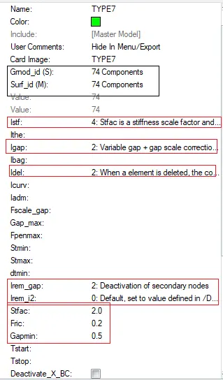
- give all the recommanded inputs for the TYPE 7 contact as shown in th figure
3.PENETRATIONS AND INTERSECTIONS:
- We have to check for the penetrations and interactons which may be caused by the contact defined
- we should clear all the penetractions and intersections before final run
- TOOLS>>PENETRATION CHECK>> set for both penetrations and intersections
- give the contact which are to checked TYPE 7 & axial TYPE 7
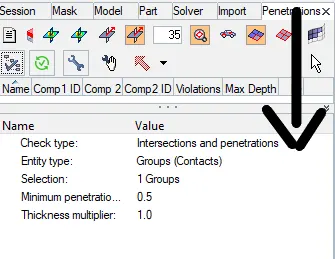
- recheck, and clear them all
4.RIGID WALL CREATION:
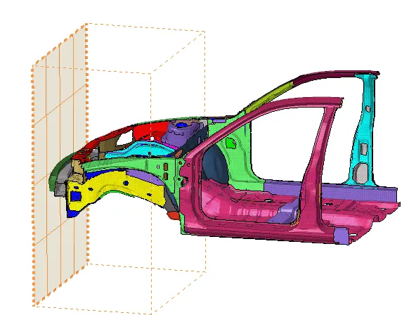
- we are performing a crash anlysis by using a rigid body so, we have to create a rigid wall
- SLOVER>>RIGID WALL>>create and give the node cordinates where the wall should be created
- set th e search distance as 1000
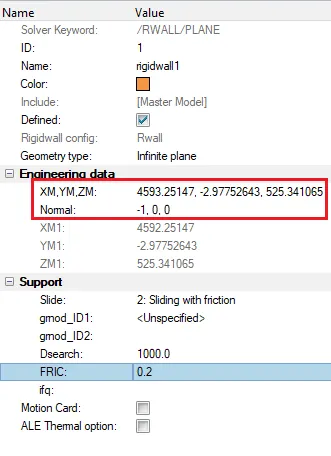
- also define the nornal , to the respective axis with respective sign
4.MASS ADDITIOAN:
- we have to know the mass of the entire components and also the center of gravity of the model
- TOOL>>CAL MASS>> select entine components
- we got to konw that the mass is 188.989 kg
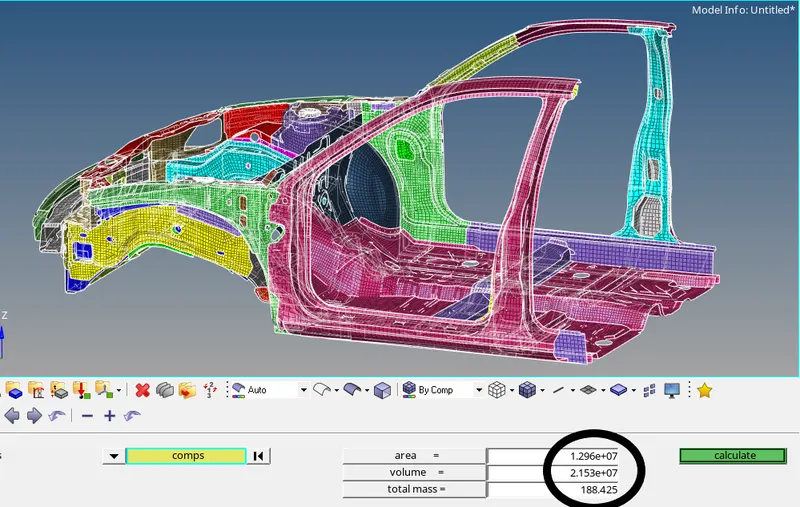
- cog of the body is as shown
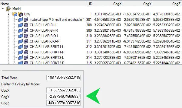
- note this coordinate of the cog and create a temp node here, for the identifivation
NOTE:Compare the model weight with the full scale 300k nodes model and use added masses to reach target weight 700kg while getting CG about the required range.
- mass is to be increased and resepective cog is to be identified
- create a new set for mass containing the nodes where we have to define the mass
NOTE: lets talk abot sets
set are nothing but the calling functions, that call a specific group of nodes, shells, etc to be identified by the slover cards, mass needed to be added on certain nodes, we select these nodes and group them as mass set and we recall this mass set in the ADMAS slover card. simillarly we can we can group N number of things in th e sets
- SOLVER>>ADMAS>> select entity as sets>> ADDMASS1/ADDMASS2
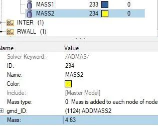
- locate the now cog for the 700kg mass
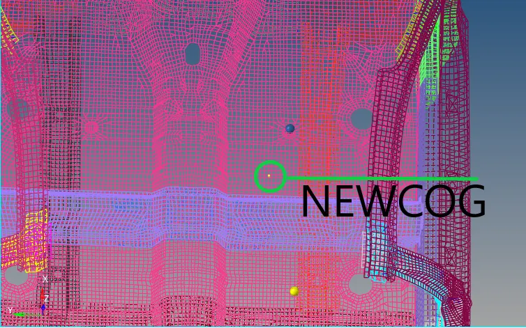
5.INITIAL VELOCITY:
- SOLVER>>CREATE>>BCS>>INVEL>>create velocity
- create a set for the velocity , selecting the components where the velocity is to be acted
- recall the velocity set i.e, gmod_id= sets >> VEL
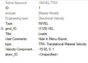
- specify the sign of the velocity correctly and convery the velocity frim 35mph to kmps
MODELCHECKER:
- This shows where the model have be wrongi.e, where the paramaters are given wrongs
- TOOLS>>MODELCKECKER>>it has 3 options ERROR,WRANINGS,INFO simulation will crash if there are any errors
- check and clear them
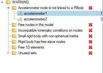
- check the status and clear the them
TIMESTEP CORRECTION:
- MODEL>> CARDS>>ENINE RUN>> TIME STEP=80 , set the simulation run time
- MODEL>>CARDS>> ENG_AINM_DT>> Tstop=0.5, enter time step between 0.1--0.5 microseconds
OUT PUT REQUESTS:
1.Sectional force in the rails at location of indicated node 174247.
here , again sets are to be created for the respectve crossections results these are to be called while defining the crossections in the SECT as grshel_id
- find the node 174247 and create the frame and sect with reference to the node
- SLOVER>--FRAME>--MOV>-- CREATE and define the node , axial, plane as shown in the dialoge box and return
- SOLVER>--SECT>--CREATE>-- define the N1,N2,N3, and call the shell set as in grshel_id and give dettaT=0.1
- do the same for the right side rail
- create out put blocks for bothas rail left and right
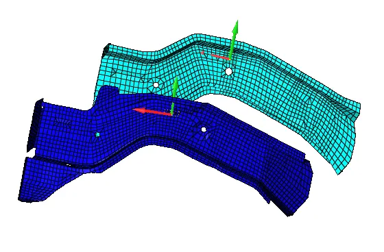
2.Axial force received on the rails from bumper.
here force recieved from rails to bumper are to be know , so we can define one as master and other as salve in contact type
NOTE; in the above interfference creation we have defined all the components as slaves and masters beacuse we are crashing the body to wall so, it all are slaves and all are masters but where as here it is asked effect on one by other so,we ca define fromas master and to as sleves
- SLOVER>--INTER>--CREATE>--TYPE7 and set entity as nodes
- fedine the master and slave nodes as shown create the outputblock and select the correct entity as groups
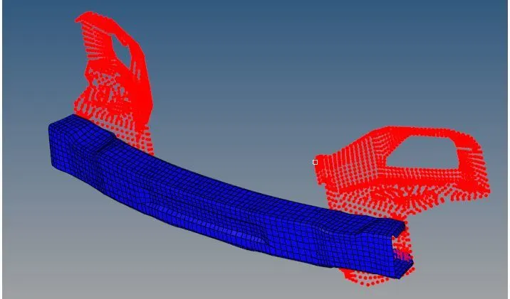
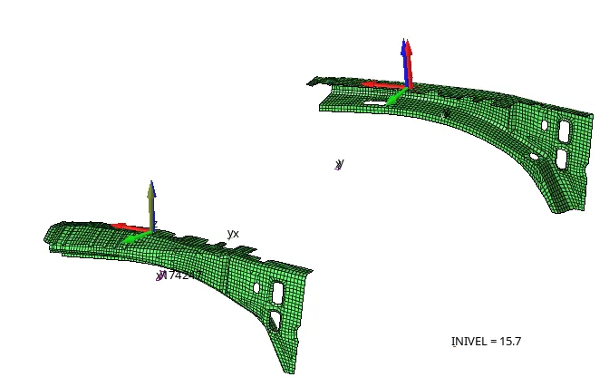
3.Shotgun cross sectional forces.
- creating the sectionalforces i.e, same as that of the above sectional forces at the given node, but we have to create at the shotgun part
- SLOVER>--FRAME>--MOV>-- CREATE and define the node , axial, plane as shown in the dialoge box and return
- SOLVER>--SECT>--CREATE>-- define the N1,N2,N3, and call the shell set as in grshel_id and give dettaT=0.1
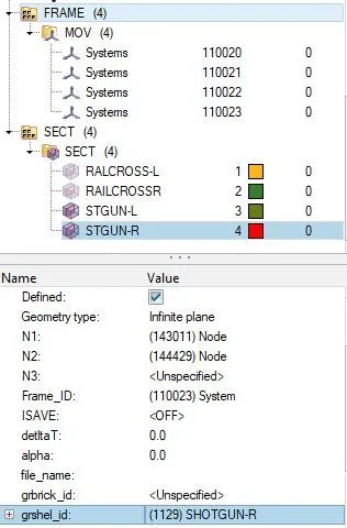
- create the out put blocks for both sides of the shotgun
- these are as shown in the figure also, see that you match with the global corordinate axis while creating a frame
- creae the output blocks entity as crossecitons
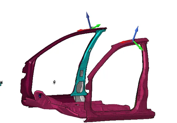
4.create the out put blocks for both sides of the shotgun
- simillar to the above , now create the sections at the pillars
- SLOVER>--FRAME>--MOV>-- CREATE and define the node , axial, plane as shown in the dialoge box and return
- SOLVER>--SECT>--CREATE>-- define the N1,N2,N3, and call the shell set as in grshel_id and give dettaT=0.1
- create outpotblocks eitity as crosscestions
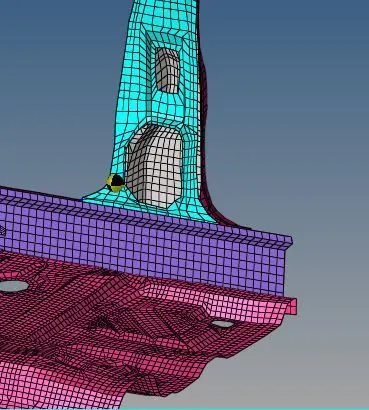
5.Acceleration curve received on the accelerometer at base of B pillar (on B pillar rocker).
- SLOVER>--ACCEL>--CREATE >-- select the respective node where the accelometers are to be diployed
- create a out put block and set the entity type as accelometer
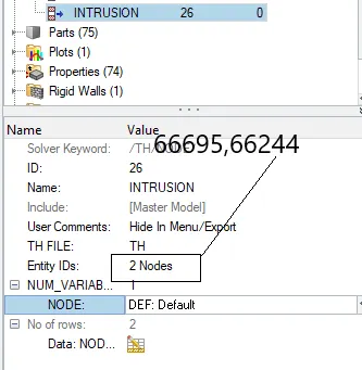
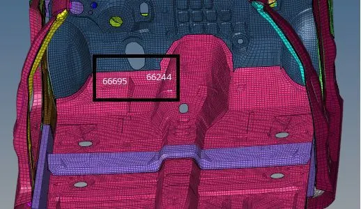
6.Intrusions on the dash wall 66695,66244.
- iitially find the nodes ny FIND command
- SLOVER>--TH>--NODE>--CREAT> give the two nodes i.e, 666955,66244
RESULTS:
All the animatios and contur plot are shown and compared with the help of graphs
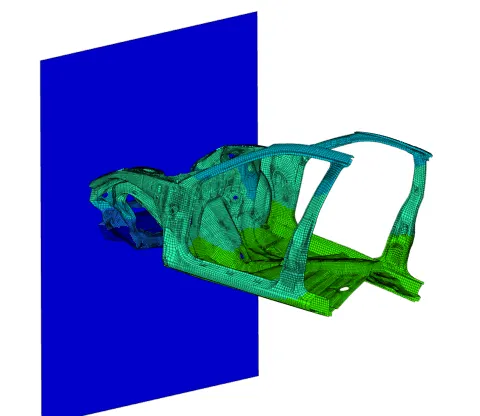
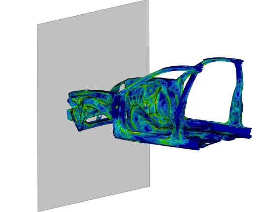
- these are the displace and vonmess animations
- displacement is nothing but the movement of the node perperficular to the surface, here the maxium displacement that occur during the maxium deformation os as given 1.378e+3mm
- vonlisssles stress are the stress that are developed during the maxum defiormationa d this is given as 3.57e-1N/mm2
sectional forces at rails, pillar, shotgun:
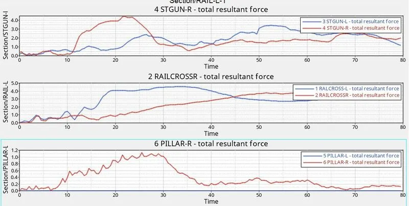
- thes are the forces that are asked to perform at required crossectins
- all the maxium forces both dor the left nd right sections are given here
- sectional forces for left anf rigth at cross railsare as given 4.35N& 3.2223N
- sectional forces for left anf rigth at shotgun crossctions are as given 3.35N& 4.5523N
- simillaruy sectional forces for left anf rigth at pillar as given 1.22N& 2.34223N
Axial force on rails from bumper:
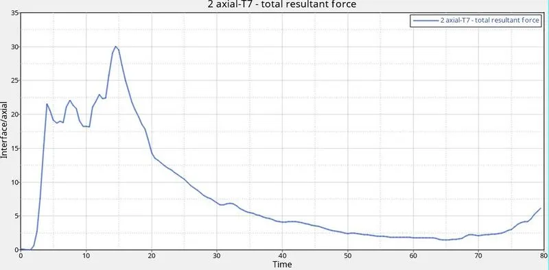
- here main intentio of this is to understanf the transmission of forces from bumper to rails
- so, we have set the bumper as master and rails as slave nodes
- final axial esultant forces are as given 30N at the time interval of 15sec
Accelometer:
- accelometers are placed at the bottom of the pillar at different node locations
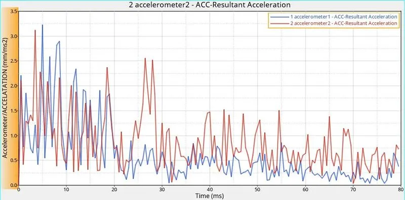
- maxium acceleration of the 2 accelomeers are as given as 3.23 mm/ms2& 3.1034mm/ms2 respectively
- also, some retardation will be recieved vy the the body after crashing
intrusions at the nodes 66695,66244:
- intrusions are applied on the given 2 nodes

- these are nothing but the displace that he nodes undergo from the origial position
- the maxium displacemnt the the node perform during crashing are as such 815.45&827.66 mm respectively
KINETIC , INTERNAL& CONTACT ENERGY:
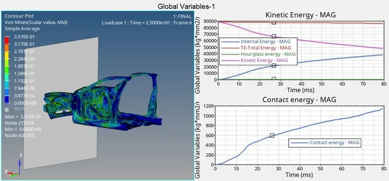
- internal and kinetic are maxiumat the satrting and decreases as the simulation takes place
- here i have set the wall in contact with the car body so, as soon as the similation begun energies begun to change
- KE is decreased to 5500J at 80 ms
- Contact energy is induced in the system when there is a change in the contact occur due to forces
- this contact energy id increased to 1150J at 80 ms
- also, as we have used the reduced integration scheme hour glass energy is zero