Crashworthiness simulation using Radioss/Hypercrash over the CAR frontal BIW structure.
AIM:- Crashworthiness simulation using Radioss/Hypercrash over the CAR frontal BIW structure.
OBJECTIVES:-
- Check the unit system and either follow[Mg mm s] or [Kg mm ms].
- Create an appropriate interface, friction 0.2, and recommended parameters.
- Make sure of no penetrations and intersection.
- Correct rigid bodies if any issues.
- Create a rigid wall with friction 0.1.
- Compare the model weight with the full-scale 300k nodes model and use added masses to reach the target weight 700kg while getting CG about the required range.
- Initial velocity 35 mph.
- Use model checker to ensure good quality.
- Time-step :0.5 to 0.1 microseconds.
- Run 80 ms.
METHODOLOGY
- Import the model in Radioss/Hypercrash workbench. (each platform has there individual PROs and CONs)
- Check the model through Solver(Radioss) or browser (Hypercrash) deck for any free parts.
- Isolate/ delete the unwanted data from the model.
- Set up different Boundry conditions, Kinematic conditions, interfaces, etc parameters.
- Also, set up the Output request related to the simulation post-process phase.
- Run the model checker (Hypercrash is recommended). and debug the errors and warnings before the simulation.
- RUN the simulation and examine the data collected in the form of graphs and animation.
Crashworthiness
Crashworthiness is the ability of any given structure to protect its occupants from getting severely injured during an impact or collision in the case of a moving structure. So for that, the Car main Structure also known as skeleton / BIW should be made up of a material that can easily absorb the impact forces and avoid unwanted injuries on both passenger and driver side. Material is not the only criterion other than that the structure geometry, connectivity between two parts, Vehicle velocity during impact, Force distribution of the force generated are also important factors.
Crashworthiness analysis can give approximate data regarding the vehicle’s structural ability to plastically deform and yet maintain a sufficient survival space for its occupants involving crashes.
Old times when actual models are made and push through this sort of harsh condition which we are gone look in short times. What happened is that after each crash-test body got damaged so severely that the prototype cant is used again. So this is a time as well as money consuming process also the data we get from these physical tests is not accurate.
Crashworthiness helps to Desing Optimization.
Frontal Crash Test:-
-Under this project, we are working on a Frontal Crash using the BIW structure. The frontal Crash Analysis is very important for the occupant as well as pedestrian safety. In the nos. of vehicles, the Engine and Transmission are located at the front and if the holding structure is not good, all the impact force may travel into the main compartment and injured the occupant very badly. To avoid that the structure, as well as a full-scale model, should go through the testing by applying different real event-based environments. Doing this sort of testing using the Experimental method is costly as well and you cant guarantee that the result would be 100% accurate.
We can perform this sort of simulation using Solvers like radioss and then discuss over the data for a better result. With the Analysis software, we will get approximately the same result as a real-world scenario. We can update the respective parts or strengthen some parts or change the material over some parts for better results. In the End, Occupant safety is an important factor that all vehicle manufacture consider to the topmost.
PROCEDURE:-
-I had got the model as you can see in the below image in this Project. As you can see the model is not a Full Body model because of the NODE Processing Limitation In the Student Version of a HypweWorks. The Student Version of Radioss only can handle the 100k nodes and the Hypercrash 10k nodes and the full-body consist of more number than that as it contains so many parts and sub-assemblies.
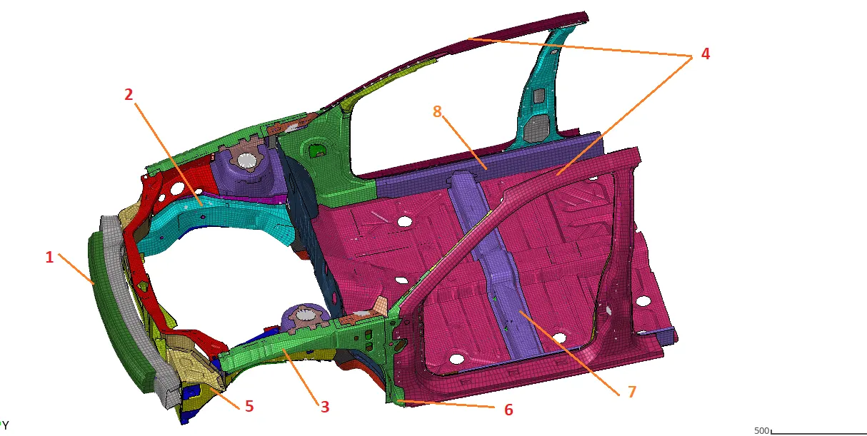
There are lots of components in this image also, Out of which I just pointed out some that we are gone work on our further simulation.
1) Bumper 5) Bumper rail
2) Support rail 6) Wheel Arch
3) Shotgun rail 7) Cross-member
4) A-pillar 8) Rocker
Unit Check
I had imported the Starter file (0.rad) in both the Radioss and Hypercrash. [Hypercrash with gave the user a better graphical interface with detailed options]
I had started the Hypercrash in kg, mm, ms, KN unit system, and my starter file not asked me if I want a unit conversion or not, so I assumed that the starter file comes with the same unit system. Only for confirmation, I had checked the starter file by opening it in the NOTE pad and find the same unit system. It's necessary to check the unit system before went ahead with further simulation because it can because of the wrong result in the feature.

-After this, I had checked for free component, But in our model all components are well connected with appropriate spring. We can check the connectivity with the "Check the connectivity of tree section " option which is available in the Quality menu of Hypercrash.
Inappropriate card or the connection data Check
-After the unit check, I had checked for any inappropriate card or the connection data that is available. Like in this model the concerned person already deleted Nos. of parts but sometimes what happens is the connection for that part is remains in the system info. and that may cause some error because the parent surface already gets deleted.
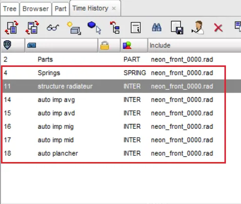
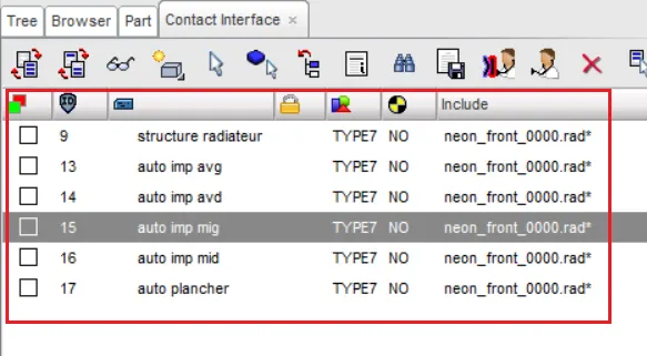
- The above two images are one of the remaining files I am talking about. This Time history and contact interface are given to the model when it is a full-scale model and the intension of these parameters are for that simulation, But for our simulation, we don't need all these parameters. All these additional files only increase the computational time and the result of these conditions gives are not that we want either, so the best option is to remove them and set conditions as per our own requirement.
-I had removed these set conditions along with some others like Unsupported card, Engine card that we won't require for this simulation, etc.
COG modification / Mass Balancing
-Now its time to Condition set up, But before that Mass and COG check is important, As in our model Nos. of parts are missing The COG and mass is not appropriate for the simulation as you can see in the below image.
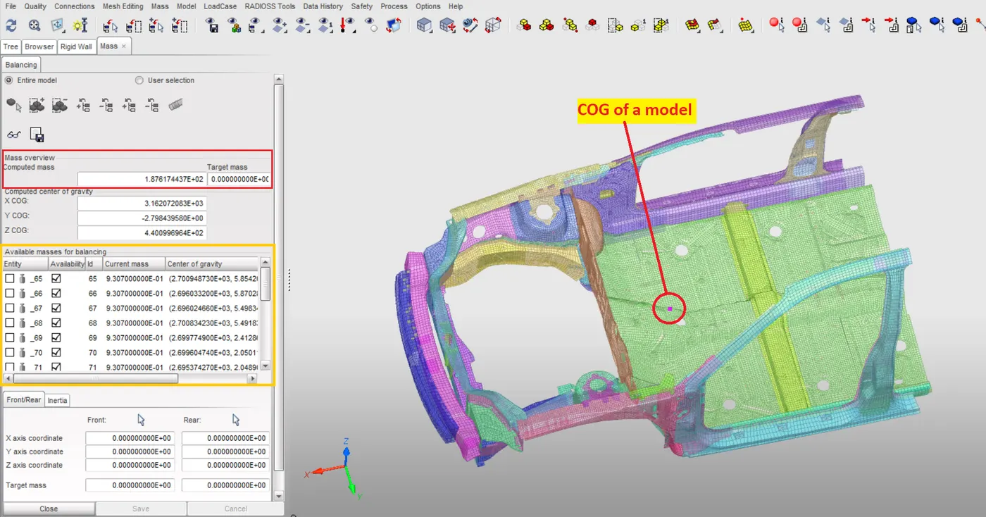
As you can see in the above image the Total mass noted by Hypercrash is 187 kg which is much lesser than the indicated 700kg mass. If we RUN the simulation as it is we will face a really BAD result as COG is shifted to much on the front side of a CAR body. In normal circumstances, the COG is near the seat and in our case, we can say it should be near the cross member.
ADMASS is the term in the MASS BALANCING in which we add some masses over the body so it can perform as a real body.
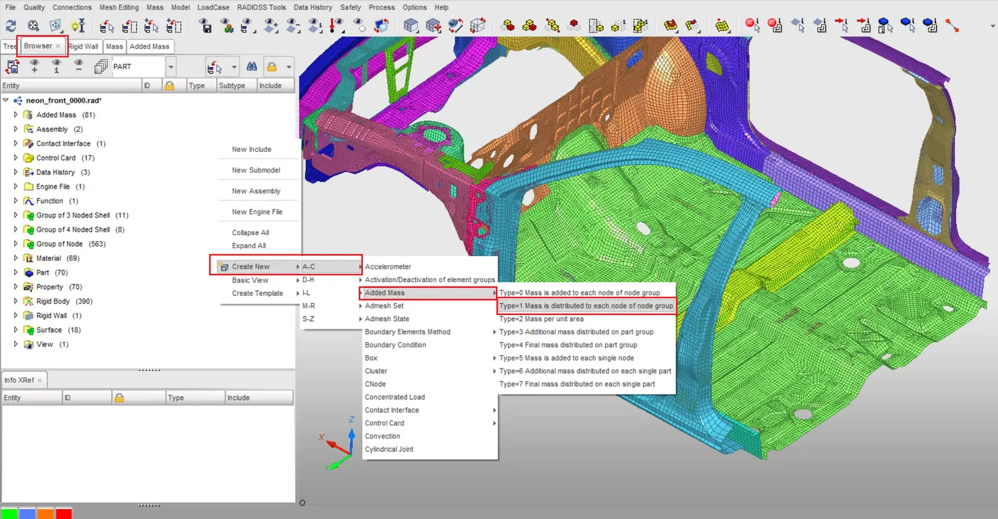
I had used that Added Mass option to add mass over the body so we can achieve our target weight and COG. I especially used TYPE 1 to Added Mass option because it will distribute the mass over the selected set of nodes and most suitable for our simulation. Under the Added Mass option we only have to select the node on which we want to do a mass addition and define the Mass we want to deploy. By using this option I had add mass at the rear end of the car body also near the Driver and passenger seat positions.
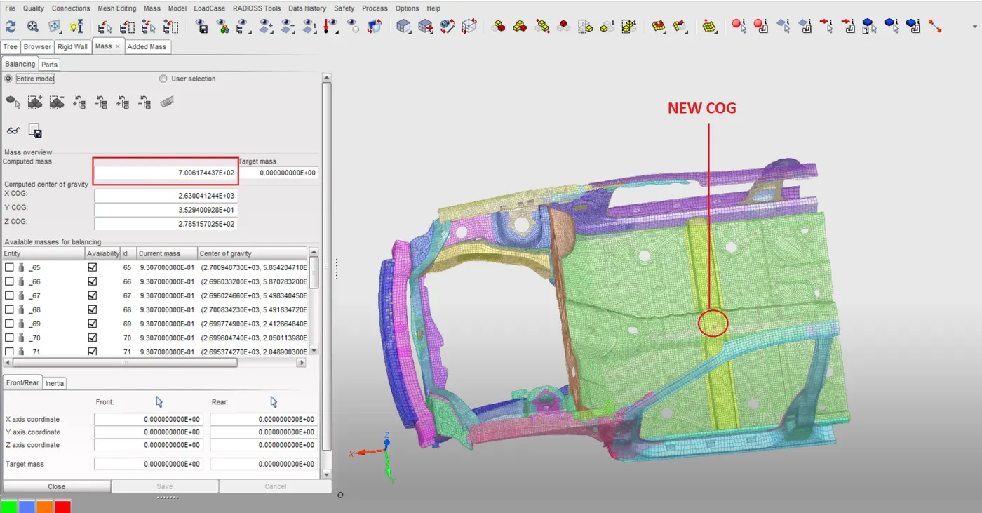
As a result, I get the desire Mass and COG at the desired position as you can see in the above image.
Contact Interface Deployation & Penetration Check
-After Mass Balancing I had moved forward for a Penetration check, But it's not valid to do a penetration check without defining the appropriate Interface connection, AS we Know that during a crash scenario the parts collide with each other as well as themselves. For that, it's mandatory to define an appropriate interface between them.
For the next step, I had decided to go with the TYPE7 interface type which is recommended and more frequently used to defined ELasto-Plastic material interface connections. For that, I had open the Interface browser in the Hypercrash and select the TYPE 7 interface [Load Case --> Contact Interface] and go with the all ideal values that are suitable for our simulation purpose.
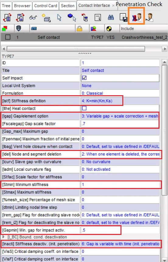
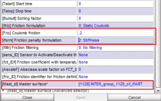
After that, I had checked for Initial Penetration in my model and removed them. To check the penetration using Hypercrash is simple and we get a shortcut button inside the Contact interface BOX as you can see in the above image extreme left. By clicking on that button we can easily check for Penetration.
In Hypercrash Steps are as follows Menu Bar --> Tool --> Penetration check
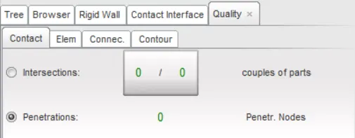
After this, I had Set up My own condition related to our simulation like Initial velocity, Timestep, simulation time, animation time, and frequency, Section forces, etc.
Initial Velocity:- as we are performing a crash test it's mandatory our moving body would collide with the rigid wall for that we have to provide our model an Initial velocity with which it can collide with the Rigid wall and we will get the result we are looking for.
to set initial velocity In hypercrash --> Load Case --> Initial velocity
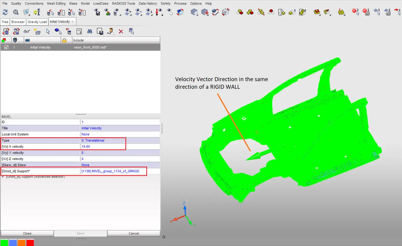
-As you can see in the above image the Initial velocity I had set up was 15.65 mm/ms which is 35mph. I dis unit conversion here. Also, I had defined the Velocity along the X-axis using a global coordinate system only.
Rigid Wall set up
-After the initial velocity set-up I had created the Rigid wall. The rigid wall allows an easy way to define an interface between the Rigid Surface and nodes of a deformable body. Here I had used an Infinite Plane type Rigid wall.
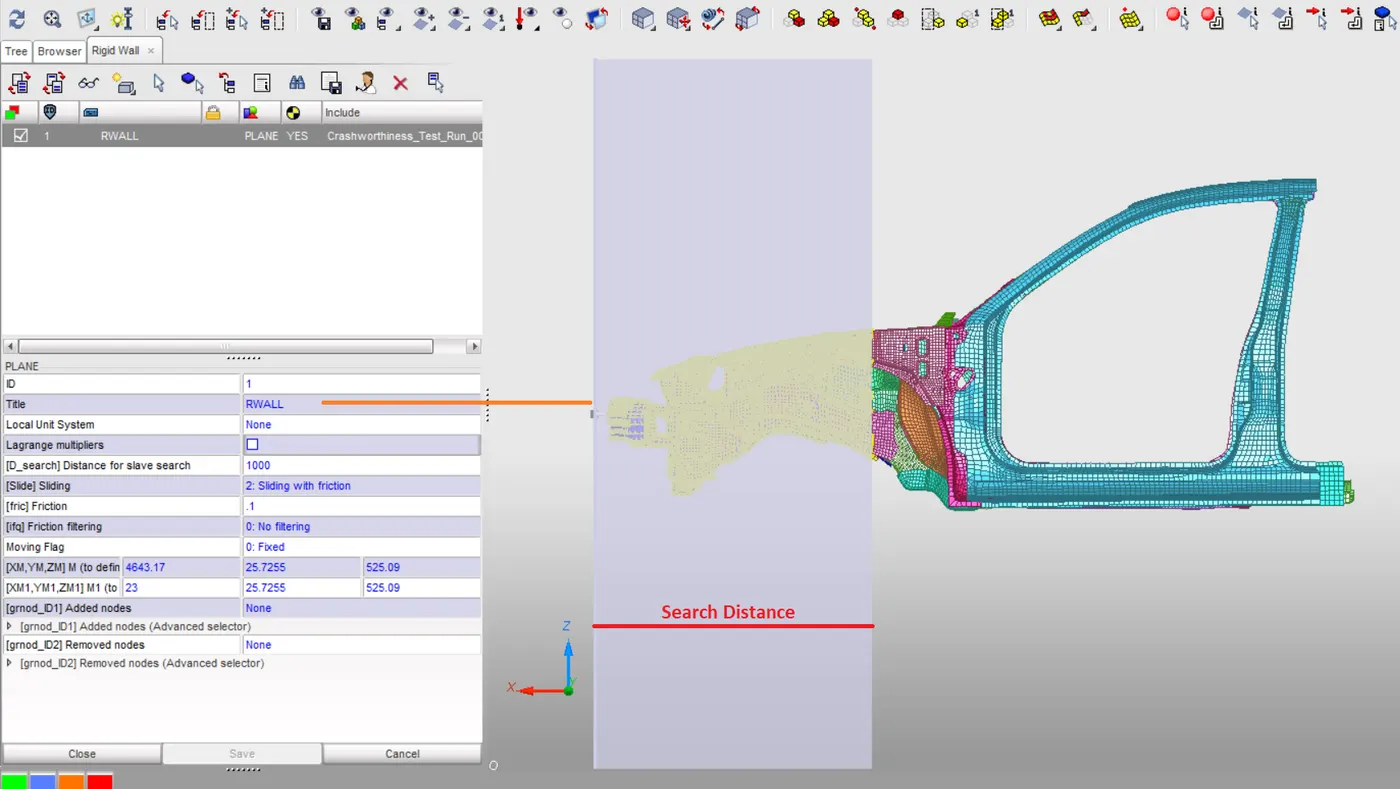
-I had defined search distance here, the nodes within this search distance behave as a slave and help to replicate the actual crash scenario of the car against the wall.
Section Setup for Section force calculation
-Now is time to setup Section Forces, we can do that by using both the Hypercrash and Radioss but I had to go with Hypercrash of this as its user interface to make it easy to create the Sections.
Hypercrash-->> Data History --> Section
To create the section we first have to select the part for which we want to calculate the section forces, by using Three nodes we have to define the section and then we can edit the section card easily by double-clicking on as we want.
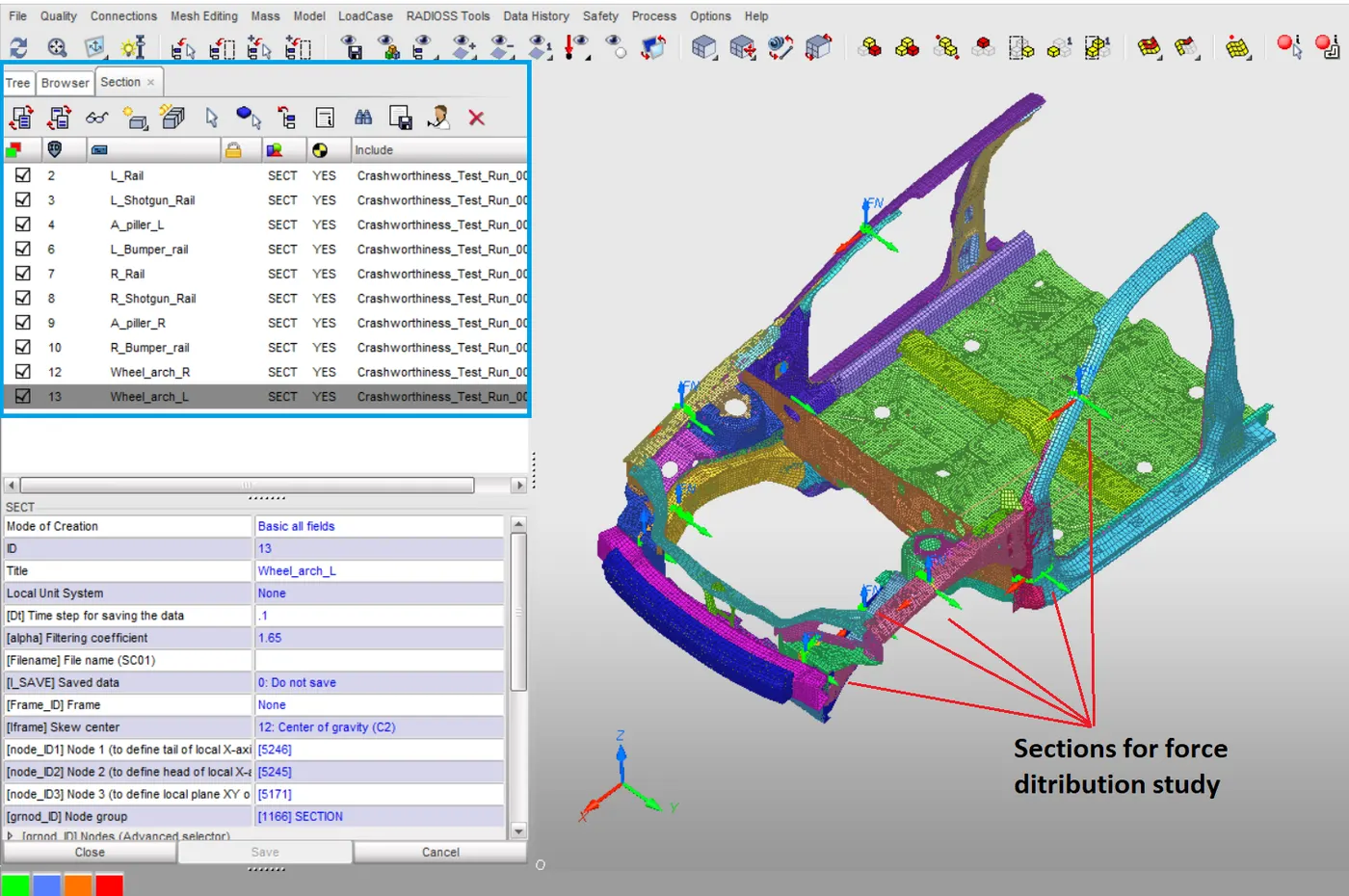
-As you can see in the above image I had crated 5 Sections for force distribution study on each side so at the end we will get the 10 sections [In the above image you had noticed that no. is not linear its because I had to delete some and create a new one while evaluating]
-To get the data from these to define sections we have to define the TH output block, One one good thing about the Hypercrash is it will automatically create the Output block for us. But if we did this in Radioss we have to do the output request separately. so this is one of the advantages of using Hypercrash.
Accelerometer Setup
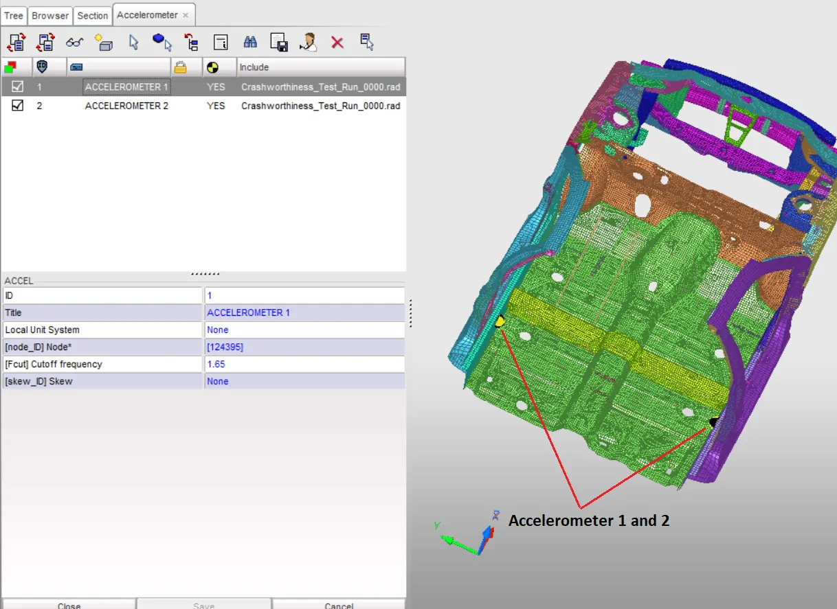
-Before moving forward with the Simulation one more thing is to set the ACCELEROMETER near the rockers. The accelerometer option computes a filtered acceleration in a skew system. Here we are defining the accelerometer using Global coordinate.
Hypercrash --> Time history --> Accelerometer
Intrusion Point setup
-After that, I had set up some Intrusions so we will get the idea about how much displacement is happening over the impact zone.
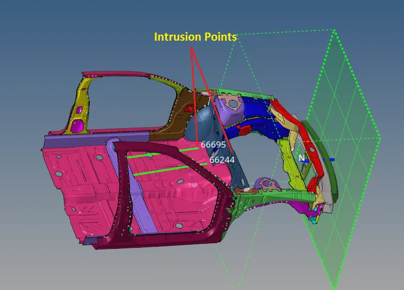
The tree blue lines you can see in the above image are nothing but intrusion points I had defined using spring (2Nodes). Also, set up the Time History request for the output of these intrusions.
Time step setup and Animation request
-After that I had set up the time step to 0.1 microsecond which is 0.001 ms in our set-up unit, Also a simulation time to 80ms and animation frequency 1, so we will get 81 frames in total at the end of the simulation.
Model Check for Errors
-Now is time to RUN the Model checker, so we can identify any hidden error in this huge model. For that in Hypercrash --> Quality --> Model checker
Radioss --> Tools --> Model Checker --> Radioss Block
I have clear these errors and warnings. All the Warnings are not harmful but the Error should be taken care of before proceeding towards the Analysis.
-After done with all the changes, I had Exported the file and open it in Radioss. go through all the parameters again and RUN the simulation for 80ms. The result I had got after the first Run is as follows,
-One thing I had noticed during examine the animation result is there is no Rear half available here and the available rear-end acts as an independent. for example, if you see the bottom animation file you will get the idea that the rear half is collapsing along with the body, and it's not a good representation. The final result we will get may not be good because of that. because the behavior is not a natural one.
Animation Results with No rigid Body at the rear half
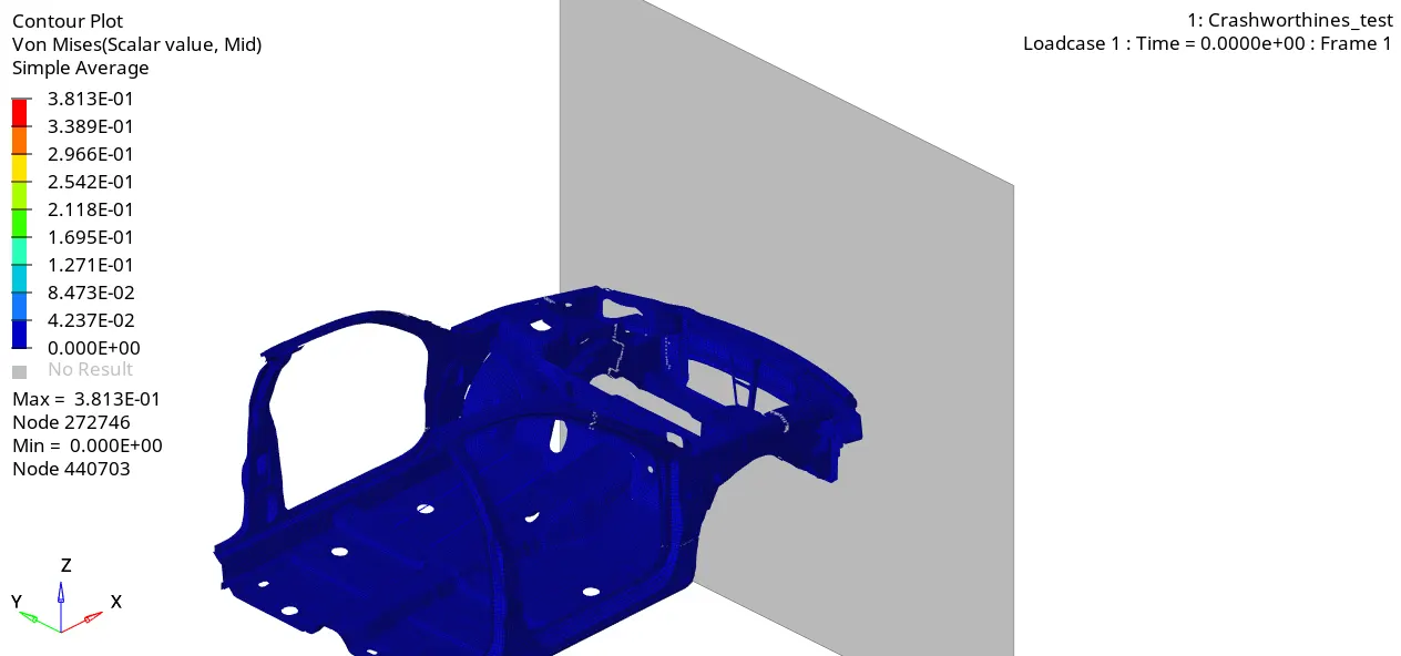
-As you can see in the above animation how is the impact happening during the frontal crash. The Result here is somewhat out of the chart this is only because we don't have a full-scale model. As per the result, we get we can conclude that there is something wrong with the deformation pattern body undergoes.
-We can avoid this sort of scenario by deploying the Rigid multinode connection to the free edges. And for the final result, I did the same, I had deployed a rigid body at the rear section to avoid unwanted deformation.
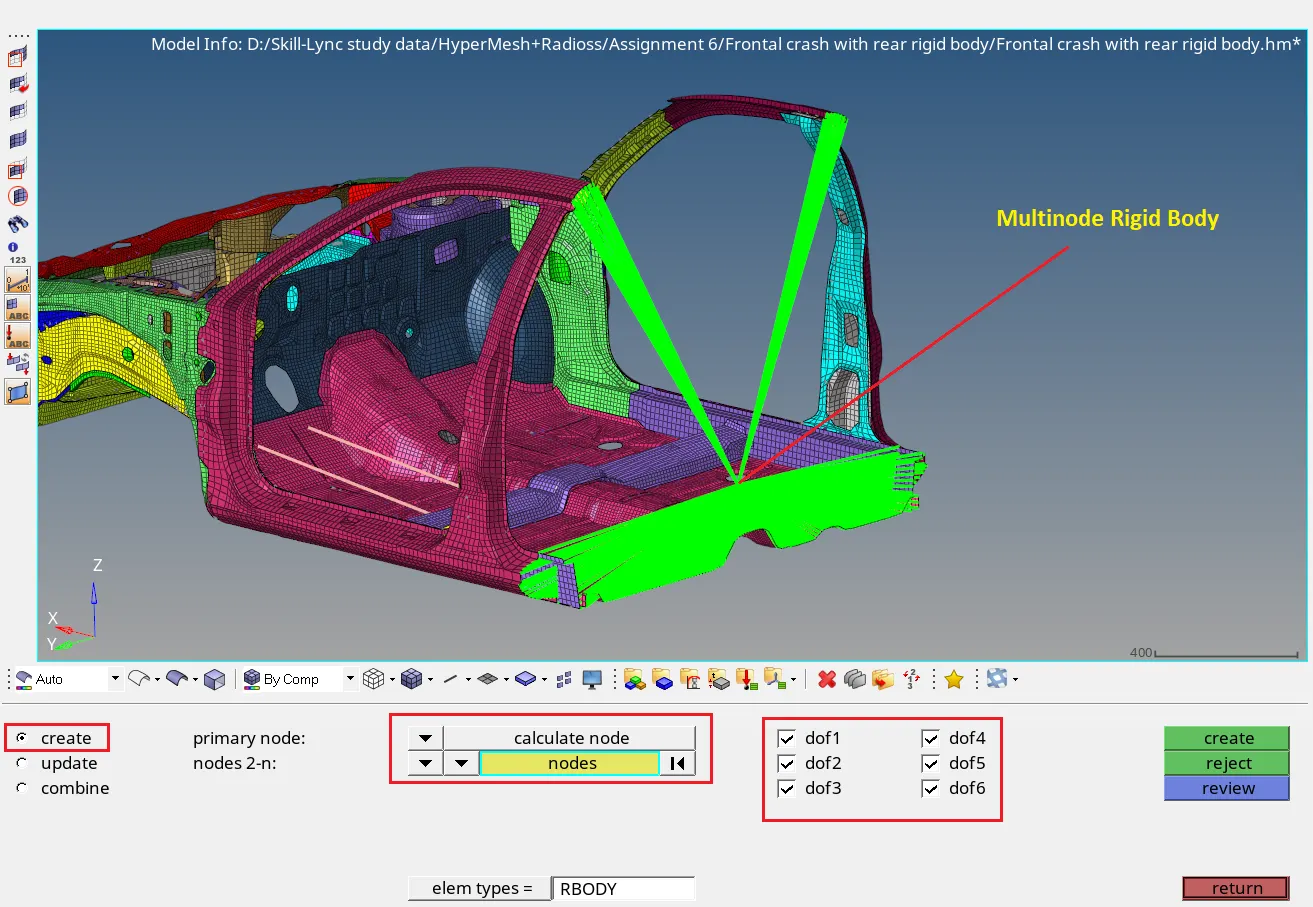
-As you can see in the above image I had connected all possible free nodes of the rear portion of the body by Multinode connection.
-The Result I had obtained after the second Run is as follows,
Animation Results with rigid Body at the rear half.
1)Von Misses stress Animation Result
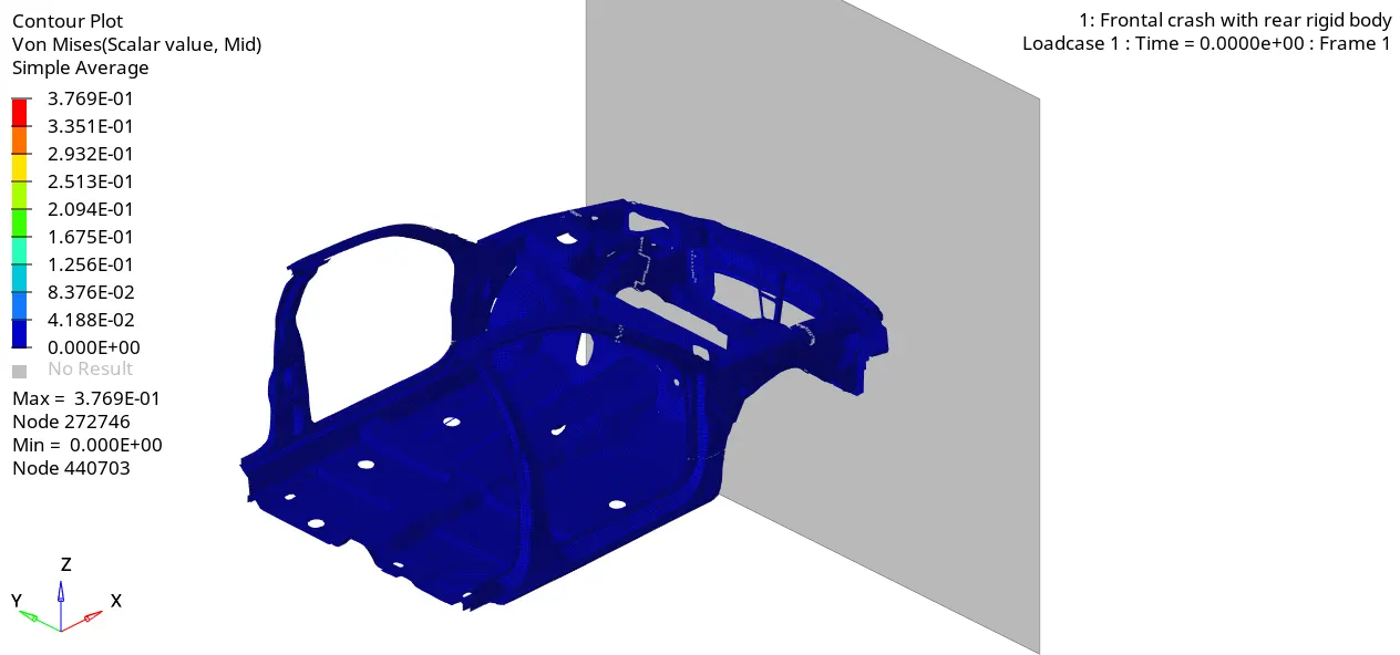
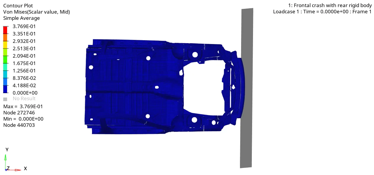
As you can see in the above animations the unwanted deformation at the rear end is dampened due to the introduction of a Rigid body. Now we can say that the model is behaving as the natural model. You can clearly see that the deformation over the left side is more than the right side. The A-pillar on the Left side is deformed very badly at the end of the 80th ms. The Max Von misses stress value registered here is 0.37 GPa.
2)Displacement Animation
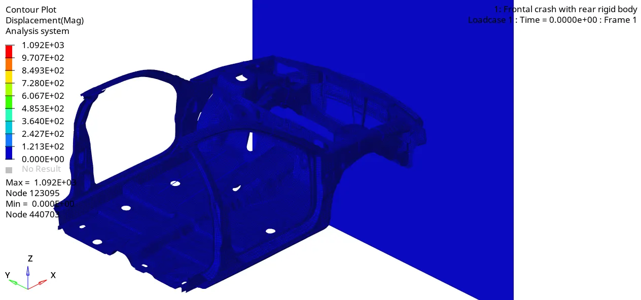
THE ENGINE OUTPUT FILE
 _______START
 _________END
-As per the Standard Energy Error should be between +5 to -15 %. and the -ve sing indicated energy dissipation, and you can see the Energy error we are getting at the end of the simulation is -1.4% which is good and acceptable. In the intermediate, this Energy error reaches the +0.9% which means energy is added to the system and after some time again starts to decrease. This indicates a stable simultaion.
-The Imposed time step which was 0.001 is larger than the nodal time step inside the Engine out file (0.00021) to compensate that the mass is added on the modes and registered as MAss error. As per the standard mass error must be less than 1% and during our simulation its 0.029% which is a good indicator of stable simulation.
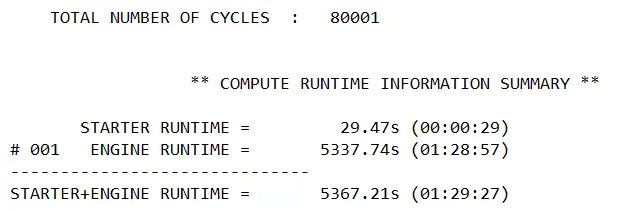
-The Total simulation time I had noticed was 1hr 29min and 27 sec.
ENERGY PLOT
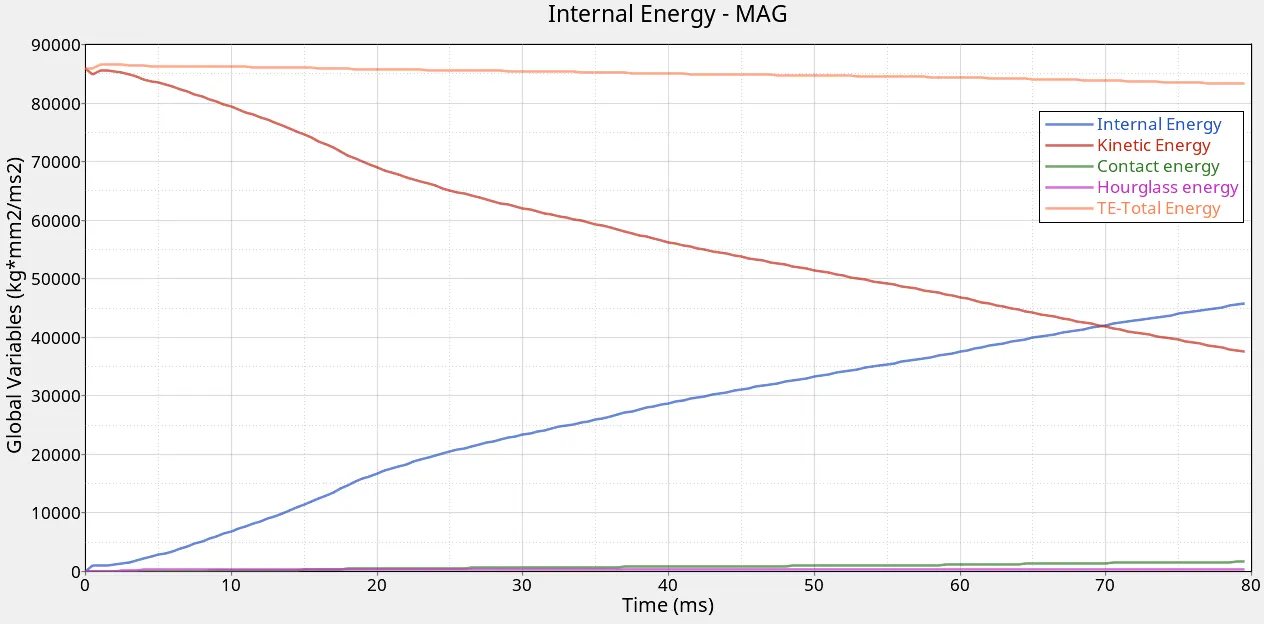
-As you can see in the above Energy plot The Internal and kinetic energies are behaving in Equilibrium. Internal energy increases in the same proportion as KE decreases. The total energy is also stable.
Sectional force in the Left and Right rails
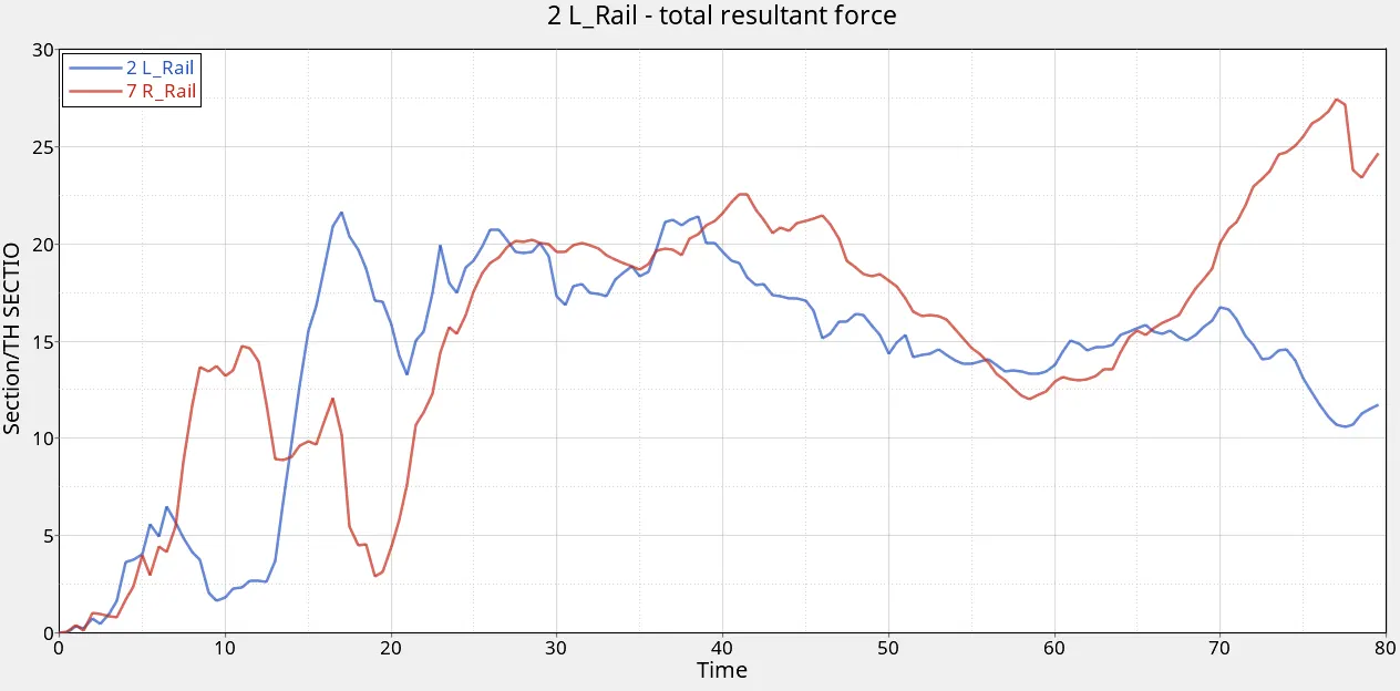
As you can see the total resultant force pass through the Right Rail is much higher at the very end. The force on the left side of the rail is increased after 13th ms and raise above the Right side one but only for a short amount of time. The peak we measured on the Left side Rail is 21.60 KN and on the Right side Rail is 27.44 KN which is at the very end. But the overall result saying that the Right side rail is undergoing maximum force during the simulation. In the intermediate period from the 25th of ms to 65th of ms, the difference between forces on both sides of the rails is not that much. This means both the real behave as they should be and try to absorb large forces of impact.
The axial force received on the rails from the bumper.
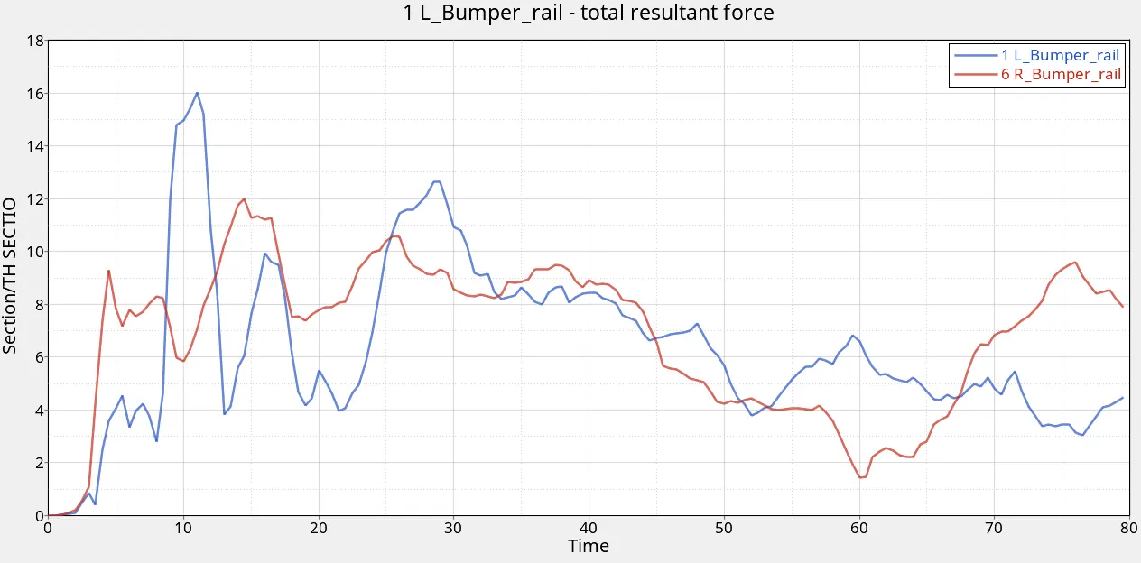
-These lefts and Right side Bumper rails are the component where the impact force comes first and then it passes to the other components from here onwards. You can clearly see that the Force noted on the Left side of the Bumper Rail is more and at approximately 12th ms it is 16KN which is maximum during the whole simulation. The max Force noted on the Right side bumper is 12 KN at approximately 28th ms.
Shotgun cross-sectional forces.
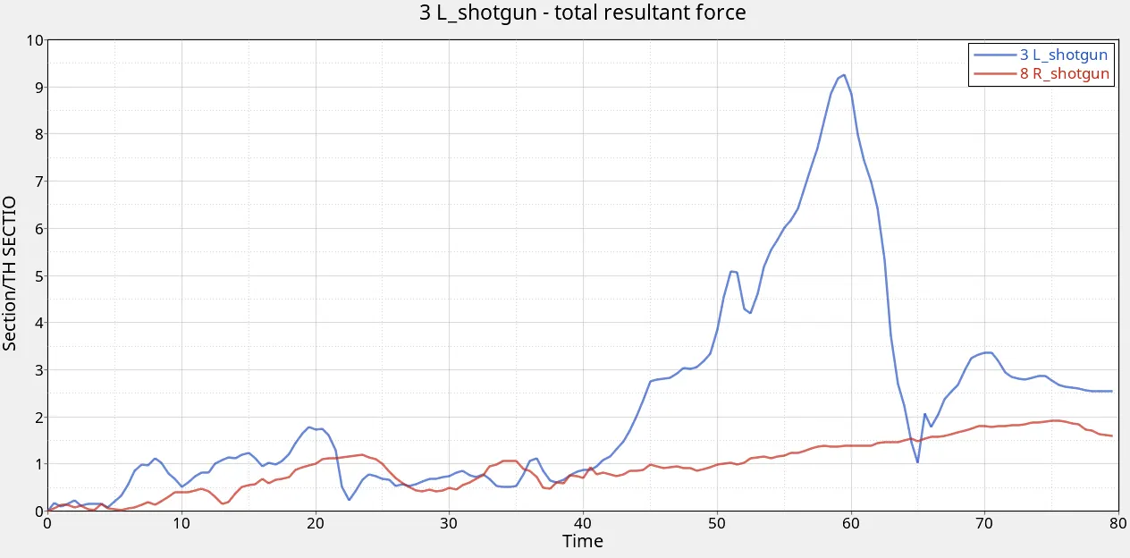
-These Shotguns rails have come after the Bumper rails. From the plot data, I can say that for up to 40th ms the force passing through both of the shotguns are not that high as we noted on Bumper rails and LR rails. Though the forces experience by Left shotgun rail is more as compare to the Right one. After the 40th ms, the forces over the Left shotgun increase drastically up to the 9.26 KN value, and the end of the 60th ms again reduced in the same manner. This sort of behavior also observed in the case of the left shotgun as the forces started increasing after 40th ms, but the increase in here is more linear than the Left one. The max value noted in the right shotgun is 1.91KN
A pillar cross-section Forces
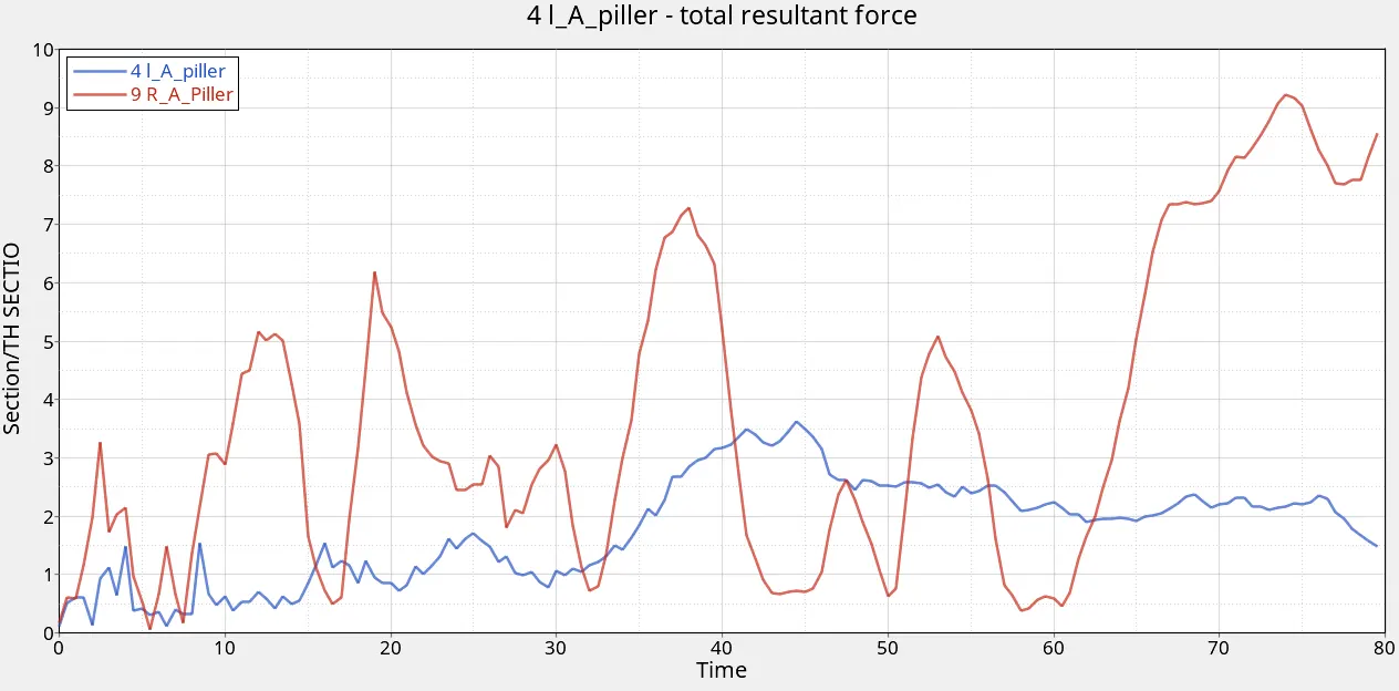
-A pillar is the very last part of our model whose comes into contact with the impact force location-wise. But one noticeable thing in this plot is the Right side A-pillar going under large force from the start to the end. means a large amount of impact force passing through the A-pillar from the start. The peak value noted on the left side of the A-pillar was 3.62 KN and on the Right Side of the A-pillar was 9.23 KN.
Acceleration curve received on the accelerometer at the base of B pillar (on B pillar rocker)
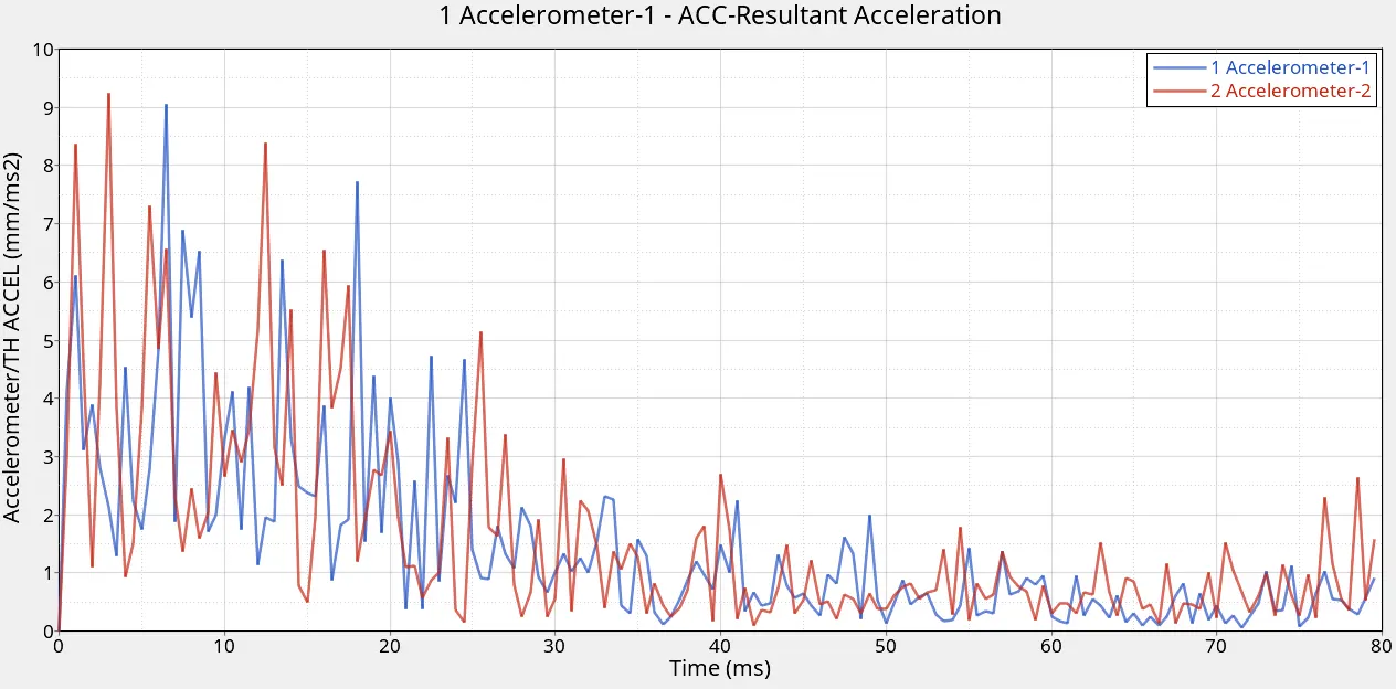
-So, from this acceleration plot, we can say that the acceleration noted at the start is high and decreases by time. The peak value noted here is 9.05 mm/ms2 on the Left side of the B-pillar rocker where I placed Accelerometer-2 and 9.23 mm/ms2 on the Right Side of the B-pillar rocker where I placed Accelerometer-1.
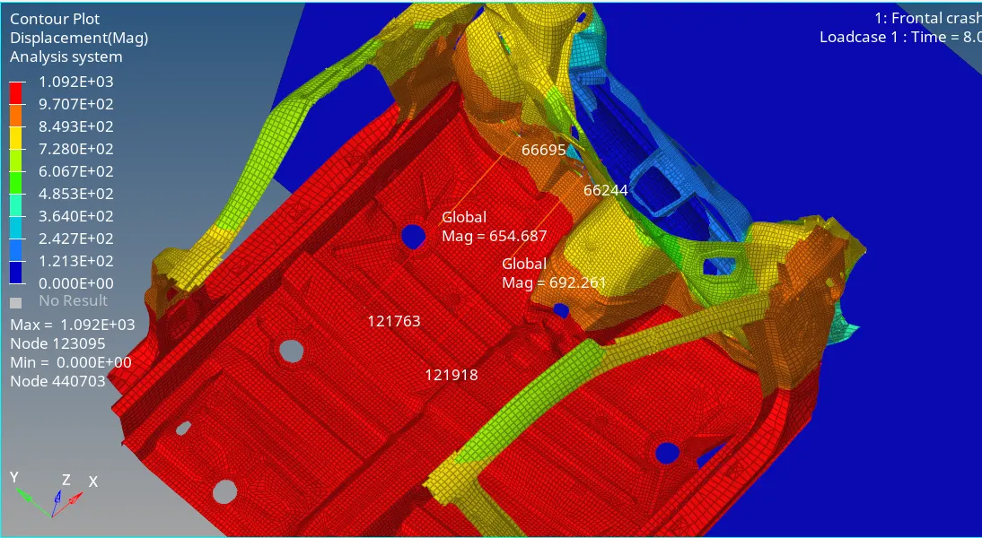
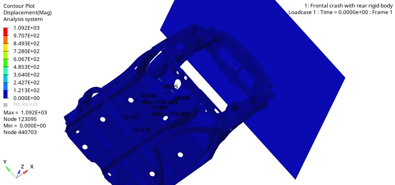
Intrusions on the dash wall 66695,66244.
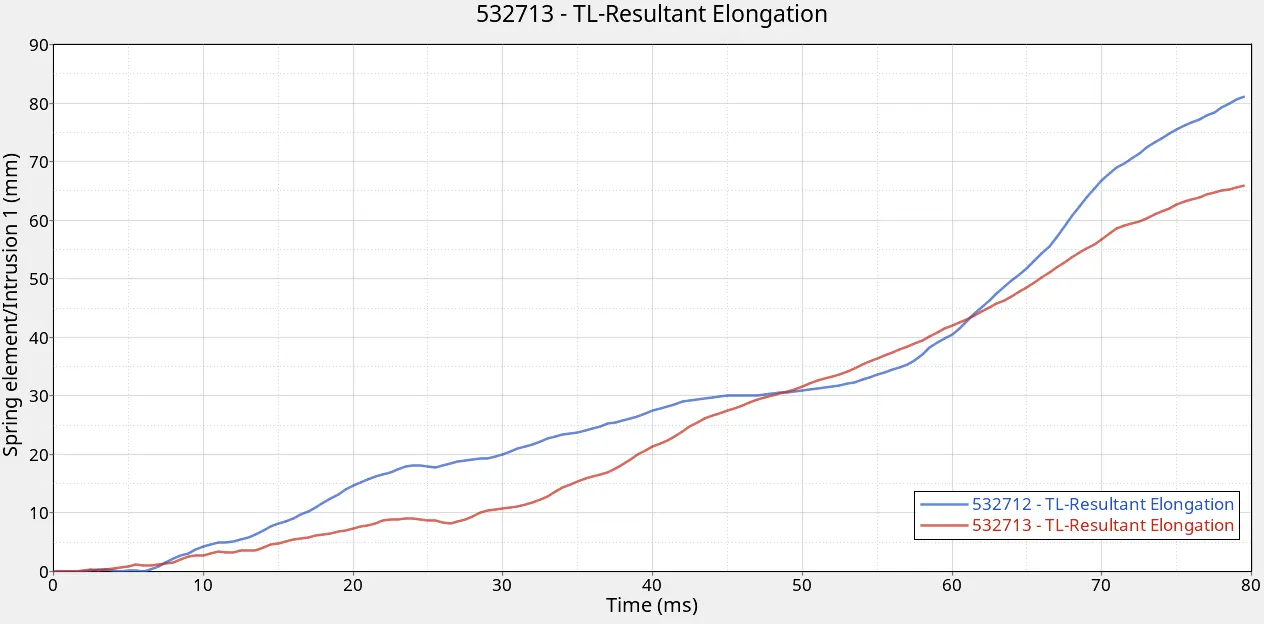
-Here you can see the displacement happen of the Intrusion points is 81.64mm max for point 66695 and 66.34mm for point 66244. I have verified this result by comparing it with the animation results.
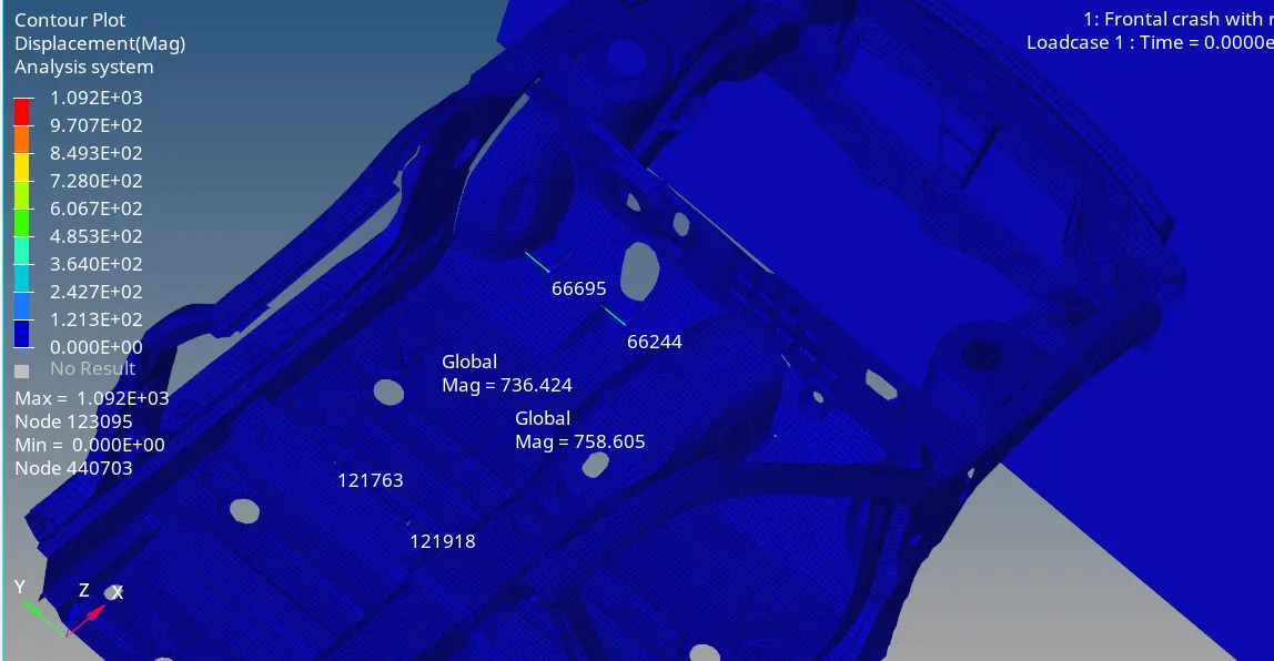
Animation Result for Intrusions
Conclusion:-
After reviewing the Starter & Engine Output file and the Animation as well as Plot data result I can conclude that the simulation is pretty stable but the data is not accurate due to the missing components and assemblies.
Also the at the start of the impact the left side of the bumper absorbed lot of force. Therefore at the start, the force experienced by Shotgun rail is less but as simulation moves forward this force started to increases but also did a great job by absorbing large force by deforming itself. as a result very less force travel to the Left side A-pillar. The deformation we are seeing in the animation, that deformation point is further ahead of the actual cross-section force indicator as a result the forces responsible for the deformation are not getting noted inside the Left A-pillar cross-section data. But it's not good behavior and needs to improve.
On the other hand On the right side Bumper rail absorbed the approximately same forces as the Left rail. At the 40th ms, the force over the Right bumper started to reduced, and the force over the Right shotgun started to increase. Also, the A-pillar over the right side experiencing a larger force (less than the bumper) from the start to the end. So we have to improve the Right side shotgun so much fewer forces travel to the rear side.
The Left and right side of the rails which is connected just behind the bumper rail experienced the most force out of all of them (Sectional force in the Left and Right rails plot). & deformed accordingly so less force will travel to the rear.