Assignment 6
A turbocharger uses engine exhaust energy to breathe more air into the combustion chamber for a more efficient engine operation.Turbochargers are basically intended to increase the power of IC engines.
List of different Turbo-chargers :
- Single-Turbo
- Twin-Turbo
- Twin-Scroll Turbo
- Variable Geometry Turbo
- Variable Twin Scroll Turbo
- Electric Turbo
Examples from GT-POWER
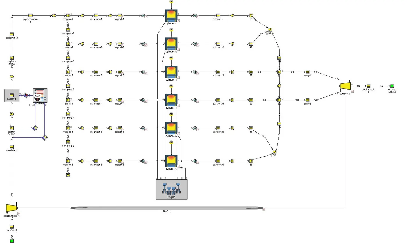
1. Twin-scroll Turbo : Twin-scroll turbochargers are better in nearly every way than single-scroll turbos. By using two scrolls, the exhaust pulses are divided and more energy is sent to the exhaust turbine, meaning more power. Following example is a twin scroll single-tubro
2. Parallel-Twin Turbo : This is about as standard as twin-turbocharging gets, using two turbochargers of the same size to work together to force air as quickly as possible into the cylinders. The exhaust gasses recycled to the turbos are split equally between the two but usually combine again in a common inlet before entering the cylinders.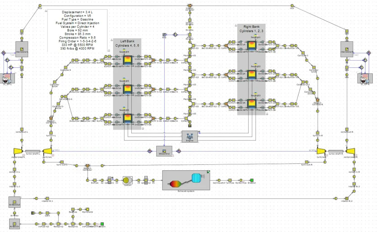
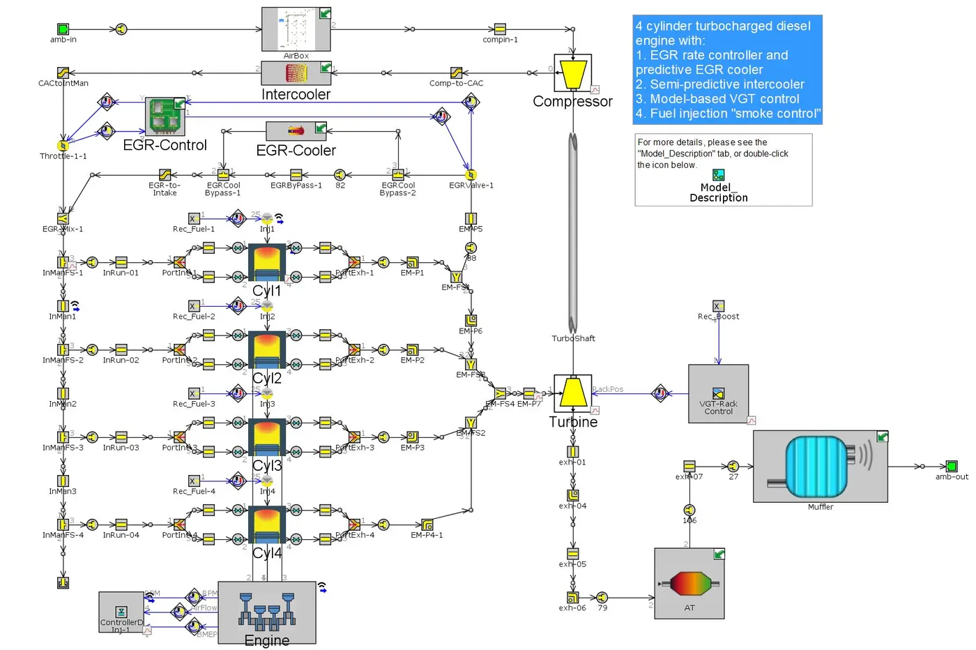
3. Variable geometry Turbo-charger : Internal vanes within the turbocharger alter the area-to-radius (A/R) ratio to match the RPM. At low RPM, a low A/R ratio is used to increase exhaust gas velocity and quickly spool up the turbocharger. As the revs climb, the A/R ratio increases to allow for increased airflow. The result is low turbo lag, a low boost threshold, and a wide and smooth torque band.
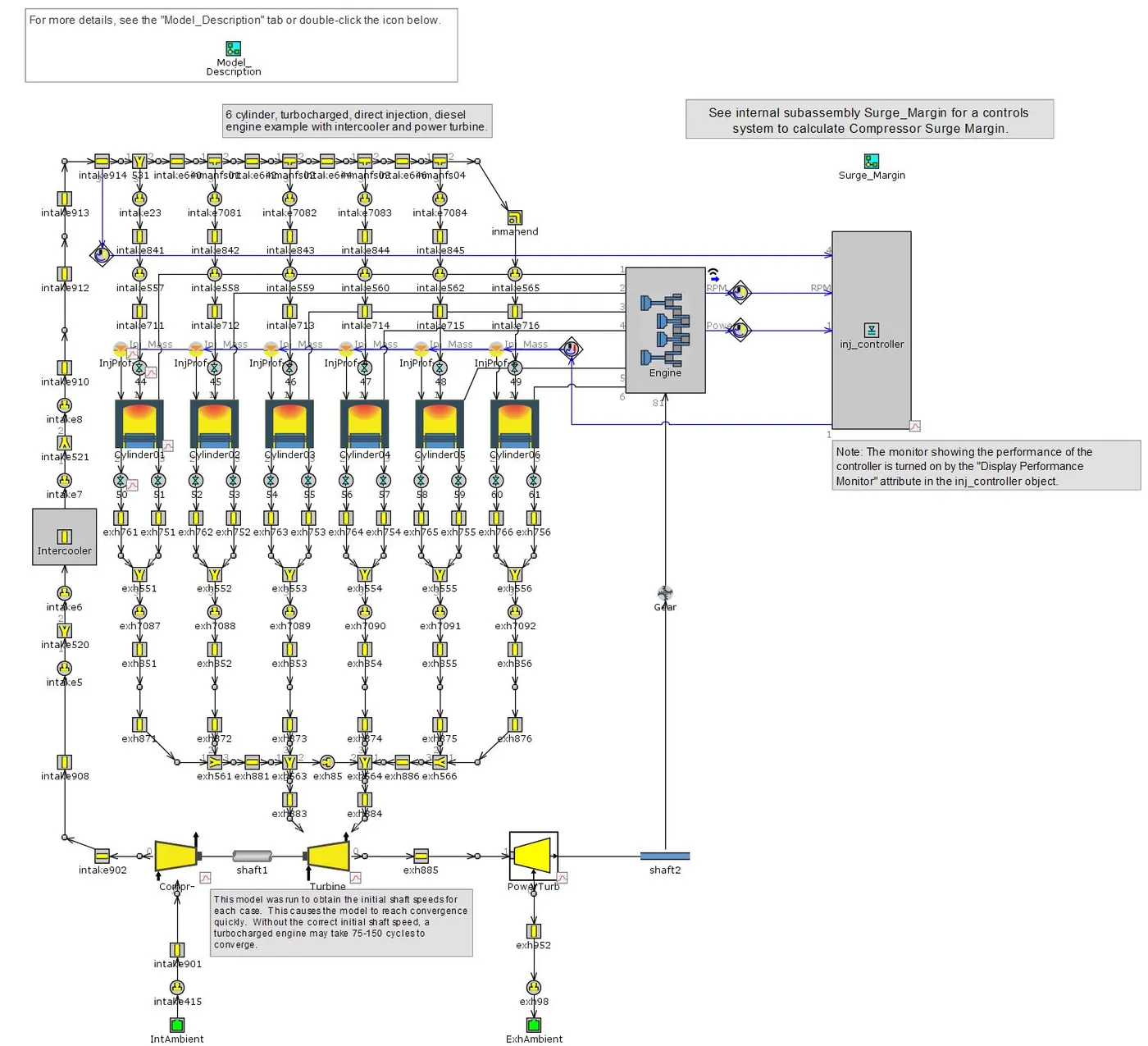
4. Fixed geometry turbo-charger : It has a simple design, where the turbine and compressor geometries are fixed and the boost pressure is entirely determined by the exhaust flow.
5. Sequential turbo-charger : This refers to a set-up in which the engine uses one turbocharger for lower engine speeds, and a second or both turbochargers at higher engine speeds. This system is intended to overcome the limitation of large turbochargers providing insufficient boost at low RPM.
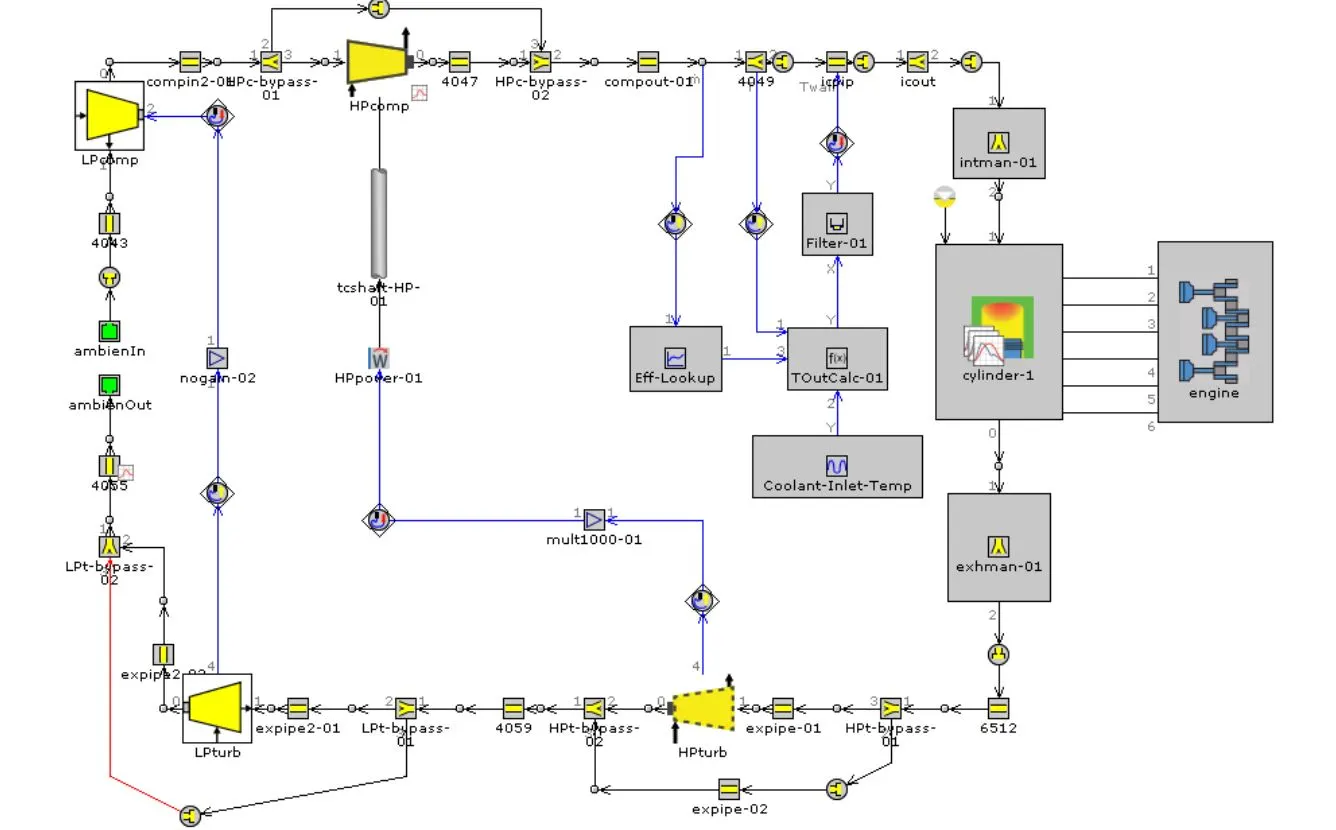
6. Waste-gate Turbocharger : This technology helps to deliver optimum engine performance during peak operating conditions. In addition, the wastegate valve prevents the turbocharger from over-running. Particularly, it also avoids the engine from over-boost and prevents any mechanical failure
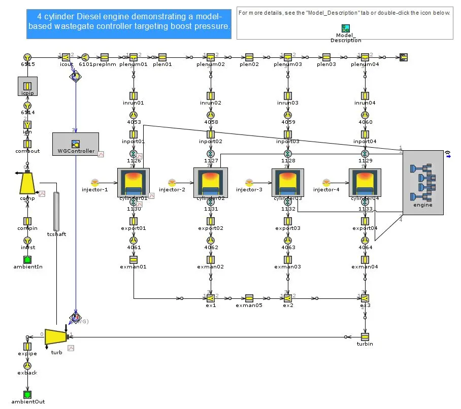
Exploring Tutorial 6 & 7
Tutorial 6 is kind of precursor to tutorial 7 where the turbine and compressor aren't connected physically but a virtual end environment is created to check the validity of the connection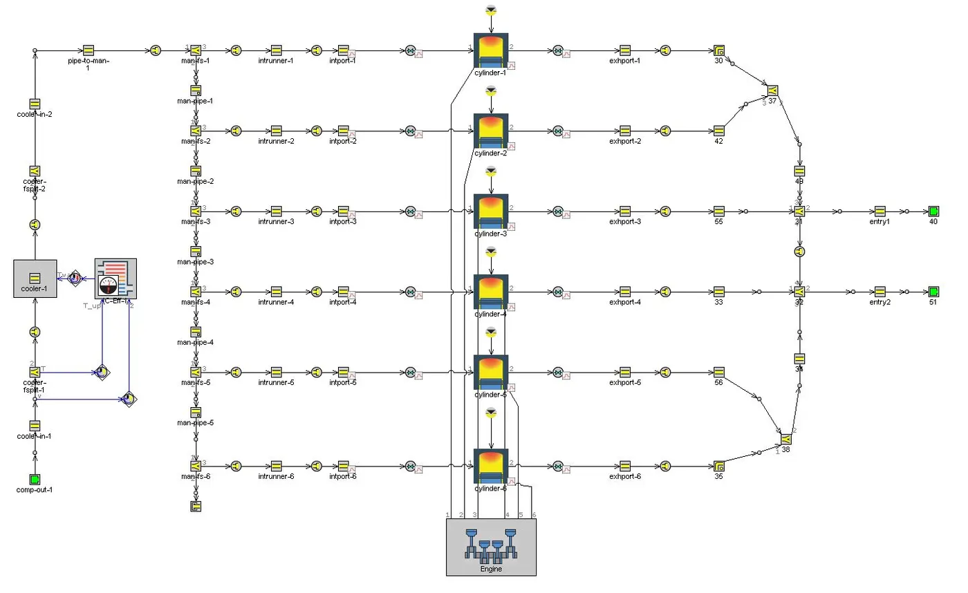
As we can see 'comp-out-1' & 'entry-1&2' are basically compressor-outlet and inlet-turbine conditions to check it's validity by assigning the similar environmental values.
On the other hand Tutorial-7 is a complete connection of turbine and compressor to the whole engine connection. This is 6-cylinder twin scroll-turbocharger.
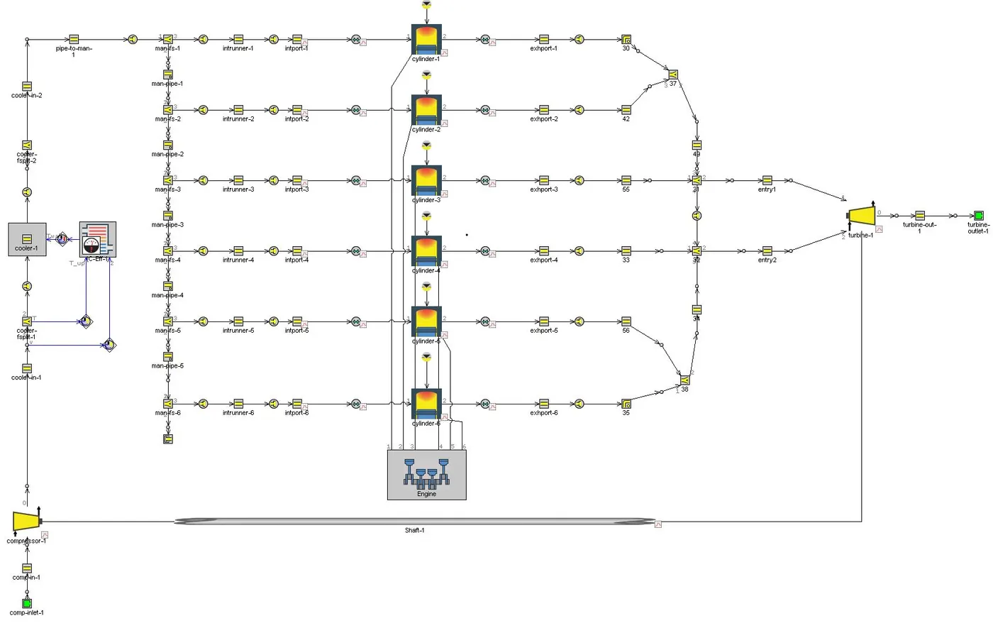
This setup is run @3600 rpm along with following inputs :
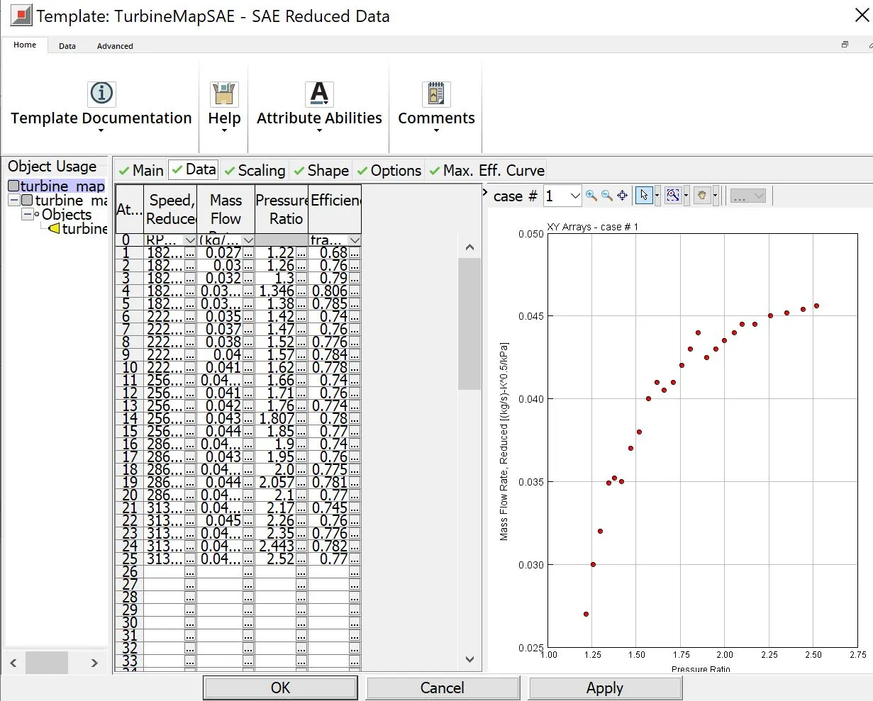
Turbine data
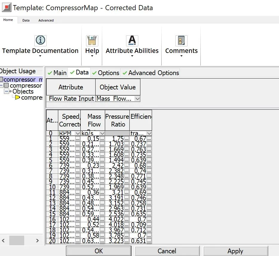
Compressor data
Turbine and Compressor Maps :
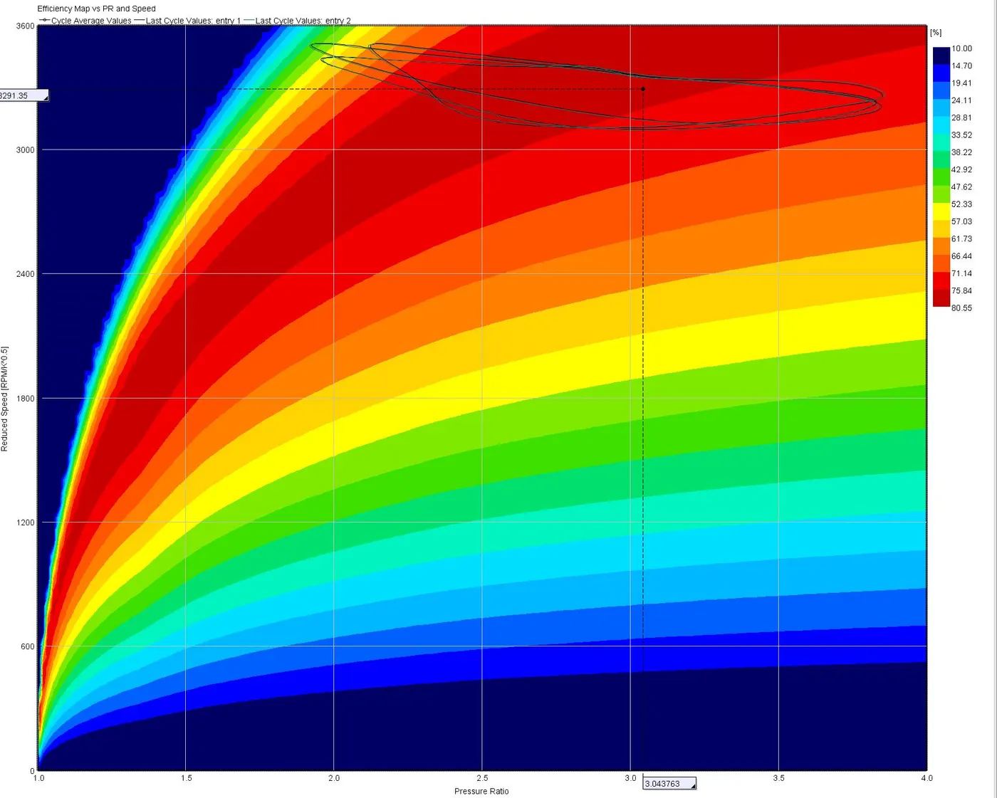
Turbine Map
The above graph is reduced speed vs pressure ratio turbine map depicting the efficiency of turbine operation i.e. @80.55% at the operating points as depicted in the roughly rounded sketch in the above graph.
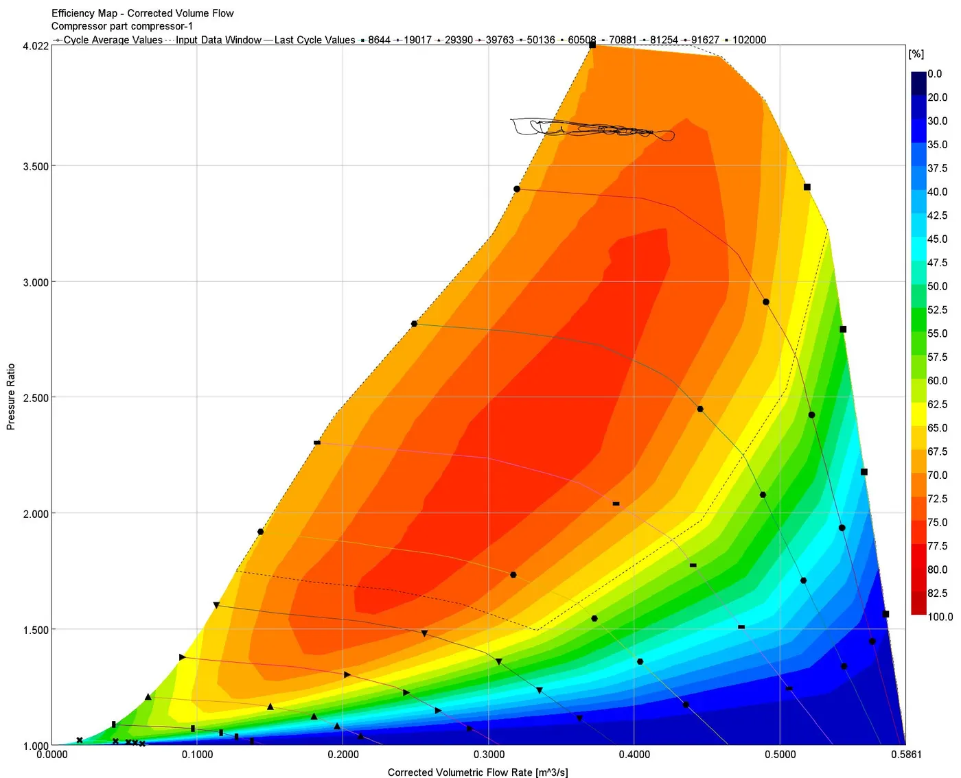
The above compressor map is pressure ratio vs coreected volume flow rate (amount of air going to the compressor). The graph has efficiency island like structure represented in colour bands and black lines as RPM of the compressor. Speed achieved by compressor @ which turbine also operates as both are coupled is around 97046 RPM .
Surge line is the operating threshold for turbo i.e. to the left boundary of the dome, operating beyond this boundary leads to fluttering vibrations
Choke line is the maximum operating condition for turbo i.e. to the right boundary of the dome causing to damage it and wear out faster. Also from the graph we can see that compressor operates at near to 70-72.5 % efficiency
When is VGT beneficial ?
This is one of the most exceptional forms of turbocharging, VGTs are limited in production (though fairly common in diesel engines) as a result of cost and exotic material requirements. Hence, only high performance end automobiles use this turbo-charger like for gasoline applications, cost typically keeps them out as exotic metals have to be used in order to maintain reliability.
It is quite effective for a wide RPM range gives a wide, flat torque curve and a single turbo can be used cutting the weight and making it compact.
Diesel VGT EGR :
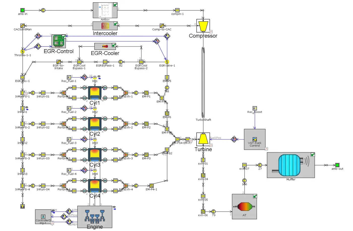
The example 'Diesel_VGT_EGR' demonstrates several modeling concepts important for automotive diesel engines, including variable geometry turbine, boost control, intercooler, EGR circuit with cooler and EGR rate control, injection limiting for smoke control, and exhaust after treatment device modeling (geometry only, no chemistry).
The Engine
The engine is a 4-cylinder, four-stroke, direct injection, 2L diesel engine. The engine runs in "speed" mode, where the engine speed is entered by the user and the engine torque is calculated. Combustion is modeled by the DIPulse method, a predictive combustion model using the detailed injection profiles. In-cylinder heat transfer is modeled using the Woschni model. A FE model is used to predict the cylinder, head and piston temperatures.
The Intake System
The intake system consists of the air piping upstream of the compressor inlet, and contains a simple model of an air box. The air box is modeled as a group of interconnected flowsplits that represent the total volume of the air box. At the inlet and outlet of the air box, "bellmouth" orifice connections are used to model smooth transitions.
The Intercooler
The intercooler is found downstream of the compressor outlet. This intercooler is an air-to-air intercooler that is modeled using a "semi-predictive" method based on heat exchanger effectiveness.
The Intake Manifold
The intake manifold is modeled as aluminum using heat conduction objects to calculate the wall temperatures.nd pressures are specified at the expected boost pressure in order to decrease the convergence time.
The Fuel Injection System
The fuel is injected directly into the cylinders. Both the injection timing and the injection profile are looked up using an 'RLTDependence' as a function of engine speed and injection rate. There is a simple control system that determines the total injected fuel mass (mg/stroke).
The Exhaust System
The exhaust manifold is modeled as cast iron using heat conduction objects to calculate the wall temperatures. This is very important in the exhaust manifold since wall temperatures change substantially between full load and idle condition, thus influencing the turbine inlet temperatures and turbine power. The orifices that connect the exhaust ports to the runners do not allow heat to be conducted between the pipe walls of the adjacent parts. The initial conditions are different from ambient conditions. The initial temperatures and pressures are specified at the expected backpressure in order to decrease the convergence time. The turbine part references a map file from which map data is read.
The EGR System
The model includes an exhaust gas recirculation (EGR) system to transport exhaust gases from the exhaust manifold back to the intake manifold. The EGR flow is driven by a positive pressure difference between the exhaust manifold and intake manifold and is controlled by an orifice connection (EGR-valve). The EGR-valve diameter is imposed by an actuator, and is determined automatically by an 'ControllerEGRValve' part to achieve a target EGR fraction. The desired EGR fraction is mapped as a function of engine speed and the requested BMEP. EGR rates in the model are as high as 40% at some operating points. Because of the high EGR rates, it is desirable to cool the EGR gases using a heat exchanger (EGR-cooler). When the pressure drop across the EGR system is not sufficient to achieve the target EGR rate, a throttle in the intake system, controlled by a PID controller, increases the pressure difference. This controller is only active, if the EGR-valve is fully open.
The Turbocharger and Boost Controller
The turbocharger in this model contains a fixed geometry compressor and a variable geometry turbine (VGT). For the VGT, there are 5 different sets of turbine map data entered at each of 5 VGT rack positions. The VGT rack position is determined by a control system to achieve a target boost pressure upstream of the intake manifold. The boost pressure is sensed and is then filtered using a 'MovingAverage' part to produce an average pressure signal. The model based controller compares the sensed boost pressure to the target boost pressure and then adjusts the VGT rack position accordingly. .
The Exhaust System
A full vehicle exhaust system is modeled downstream of the turbine outlet. The geometry of a Diesel Oxidation Catalyst (DOC) is modeled using a 'CatalystBrick' part. In this example only the pressure drop across the DOC is of interest, so no chemical reactions are modeled in the DOC. The inlet and outlet of the DOC must be modeled using flowsplits because the DOC is effectively a bundle of very small pipes.