Assignment 6
Assignment 6
- AIM:
- Exploring turbocharger and its IC engine applications.
- OBJECTIVE:
- List down different TC and locate examples from GT Power.
- Explore tutorial number 6 and 7.
- Plot operating points on compressor and turbine maps.
- In which application Variable Geometry Turbine is beneficial?
- Explore example- Diesel VGT EGR and understand the modelling part.
- Procedure:
Turbocharger
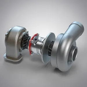
Introduction
- A turbocharger, (or turbo), is a turbine-driven forced induction device that increases an internal combustion engine’s efficiency and power output by forcing extra air into the combustion chamber.
- This improvement over a naturally aspirated engine’s power output is due to the fact that the compressor can force more air and proportionately more fuel into the combustion chamber than atmospheric pressure alone.
- In naturally aspirated piston engines, intake gases are “pushed” into the engine by atmospheric pressure filling the volumetric void caused by the downward stroke of the piston (which creates a low-pressure area), similar to how liquid is drawn up into a syringe.
- The objective of a turbocharger is to improve an engine’s efficiency by increasing the density of the intake gas (usually air), thereby allowing more power per engine cycle.
- The turbocharger’s compressor draws in ambient air and compresses it before it enters into the intake manifold at increased pressure. This results in a greater mass of air entering the cylinders on each intake stroke. The power needed to spin the centrifugal compressor is derived from the kinetic energy of the engine’s exhaust gases.
- A turbocharger may also be used to increase fuel efficiency without increasing power. This is achieved by recovering waste energy in the exhaust and feeding it back into the engine intake.
- By using this otherwise wasted energy to increase the mass of air, it becomes easier to ensure that all fuel is burned before being vented at the start of the exhaust stage.
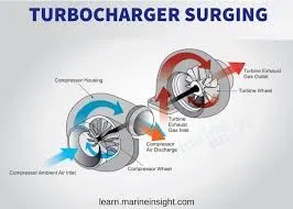
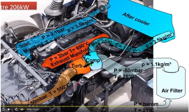
Image1: Flow inside turbocharger Image2: Turbocharger plumbed in a car
Types of Turbocharger
The world of turbocharging has about as much variety as engine layouts.
Let’s take a look at the different types:
- Single-Turbocharger
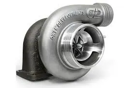
Single turbochargers alone have limitless variability.
Differing the compressor wheel size and turbine will lead to completely different torque characteristics.
Large turbos will bring on high top-end power, but smaller turbos will provide better low-end grunt as they spool faster.
There are also ball bearing and journal bearing single turbos.
Ball bearings provide less friction for the compressor and turbine to spin on, thus are faster to spool (while adding cost).
Advantages:
- Cost effective way of increasing an engine’s power and efficiency.
- Simple, generally the easiest of the turbocharging options to install.
- Allows for using smaller engines to produce the same power as larger naturally-aspirated engines, which can often remove weight.
Disadvantages:
- Single turbos tend to have a fairly narrow effective RPM range.
- This makes sizing an issue, as you’ll have to choose between good low-end torque or better high-end power.
- Turbo response may not be as quick as alternative turbo setups.
- Twin-Turbocharger (Sequential turbos).
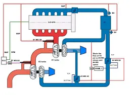
Having to choose between a small low-end turbo or a big high-end one presents a rather intuitive solution: t two, one small and one large. That way you have a small turbo that kicks in early and provides good torque, and a bigger one that offers top-end grunt, resulting in a wide and at torque curve. On the downside, quite obviously, you’re left with an engine set-up that is expensive, heavy and complex.
Advantages
- For parallel twin turbos on ‘V’ shaped engines, the benefits (and drawbacks) are very similar to single turbo setups.
- For sequential turbos or using one turbo at low RPM and both at high RPM, this allows for a much wider, atter torque curve.
- Better low-end torque, but the power won’t taper at high RPM like with a small single turbo.
Disadvantages
- Cost and complexity, as you’ve nearly double the turbo components.
- There are lighter, more efficient ways of achieving similar results (as discussed below).
- Twin-Scroll Turbocharger
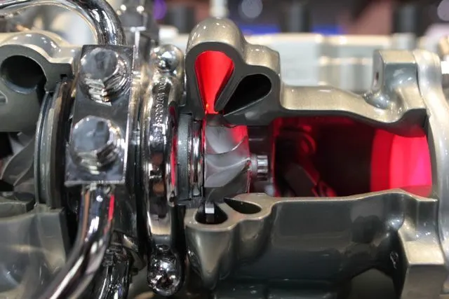
A turbo is powered by exhaust gases that are redirected to spin turbine blades and force air into the engine. Now, an engine’s cylinders re in sequence, meaning that exhaust gases enter the turbo in pulses. As you can probably imagine, these pulses can easily overlap and interfere with one another when powering the turbo, and a twin-scroll turbocharger solves this issue by using a divided-inlet turbine housing and a specific exhaust manifold that pairs the right cylinders to each scroll. In a four-cylinder vehicle, you can then have the rst and fourth cylinders powering one scroll, and two and three powering another. This means that there’s less pulse overlap and less lag.
Advantages
- More energy is sent to the exhaust turbine meaning more power More energy is sent to the exhaust turbine, meaning more power.
- A wider RPM range of effective boost is possible based on the different scroll designs.
- More valve overlap is possible without hampering exhaust scavenging, meaning more tuning flexibility.
Disadvantages
- Requires a specific engine layout and exhaust design (eg: I4 and V8 where 2 cylinders can be fed to each scroll of the turbo, at even intervals).
- Cost and complexity versus traditional single turbos.
- Variable Geometry Turbocharger (VGT)
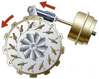
Perhaps one of the most exceptional forms of turbocharging, VGTs are limited in production (though fairly common in diesel engines) as a result of cost and exotic material requirements. Internal vanes within the turbocharger alter the area-to-radius (A/R) ratio to match the RPM. At low RPM, a low A/R ratio is used to increase exhaust gas velocity and quickly spool up the turbocharger. As the revs climb, the A/R ratio increases to allow for increased airflow. The result is low turbo lag, a low boost threshold, and a wide and smooth torque band.
Advantages
- Wide, at torque curve. Effective turbocharging at a very wide RPM range.
- Requires just a single turbo, simplifying a sequential turbo setup into something more compact.
Disadvantages
- Typically, only used in diesel applications where exhaust gases are lower so the vanes will not be damaged by heat.
- For gasoline applications, cost typically keeps them out as exotic metals have to be used in order to maintain reliability.
- The tech has been used on the Porsche 997, though very few VGT gasoline engines exist as a result of the cost associated.
- Electric Turbocharger:
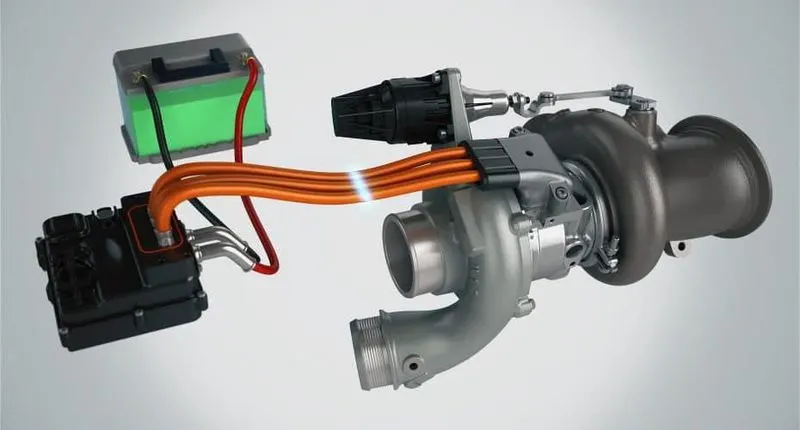
An electric turbocharger is used to eliminate turbo lag and assist a normal turbocharger at lower engine speeds where a conventional turbo is not most efficient. This is achieved by adding an electric motor that spins up the turbo’s compressor from start and through the lower revs, until the power from the exhaust volume is high enough to work the turbocharger. This approach makes turbo lag a thing of the past, and significantly increases the RPM band within which the turbo will efficiently operate. So far, so good. It appears that electronic turbos are the answer to all the negative characteristics of conventional turbochargers, however there are some disadvantages. Most are around cost and complexity, as the electric motor must be accommodated and powered, plus also cooled to prevent reliability issues.
Advantages
- By directly connecting an electric motor to the compressor wheel, turbo lag and insufficient exhaust gases can be virtually eliminated by spinning the compressor with electric power when needed.
- By connecting an electric motor to the exhaust turbine, wasted energy can be recovered (as is done in Formula 1).
- A very wide effective RPM range with even torque throughout.
Disadvantages
- Cost and complexity, as you now must account for the electric motor and ensure it remains cool to prevent reliability issues.
- That goes for the added controllers as well.
- Packaging and weight become an issue, especially with the addition of a battery on board, which will be necessary to supply sufficient power to the turbo when needed.
- VGTs or twin-scrolls can offer very similar benefits (though not at quite the same level) for a significantly lower cost.
Locating examples of Turbocharger from GT Power
Diesel-CI engine Examples
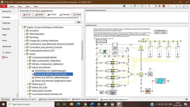
Diesel_4cyl_DIPulse_injcircuit
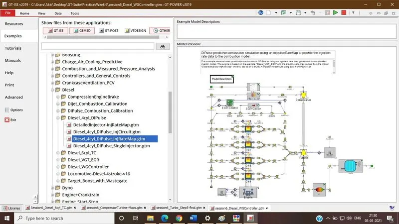
Diesel_4cyl_DIPulse_injratemap
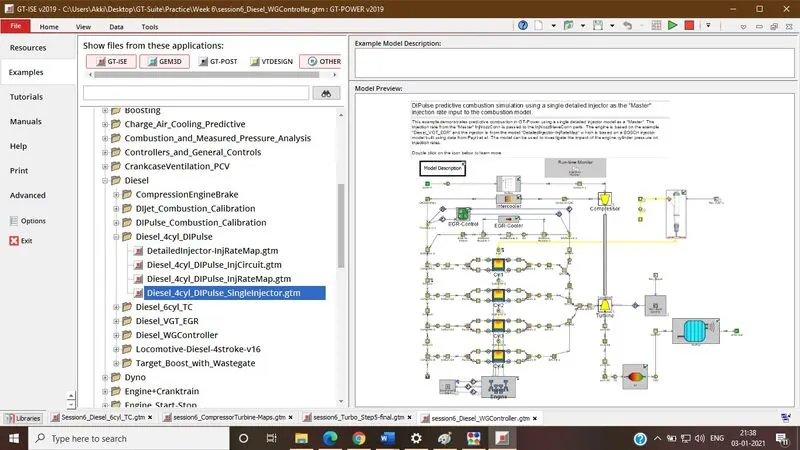
Diesel_4cyl_DIPulse_singleinjector
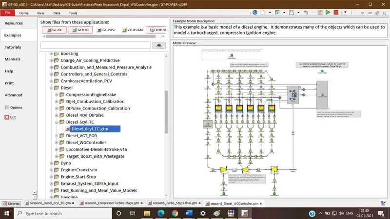
Diesel_6Cyl_TC
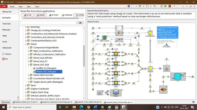
Diesel_VGT_EGR
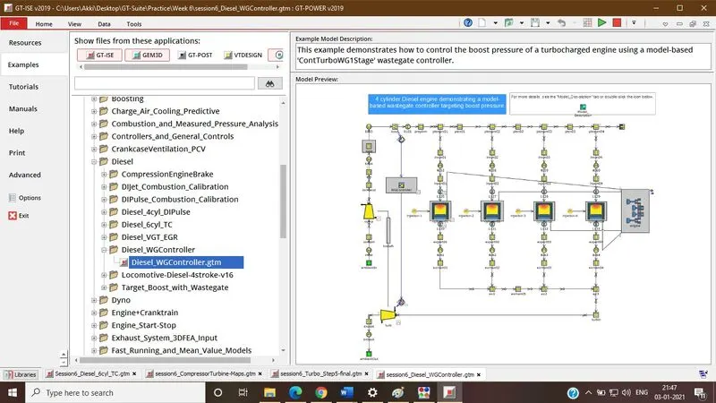
Diesel_WGController
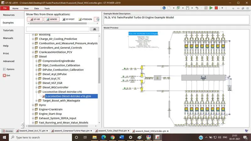
Diesel_4stroke_V16
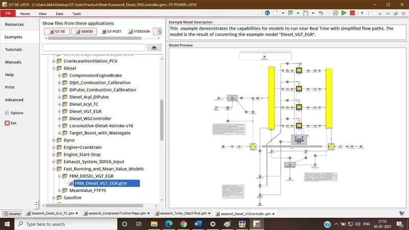
Diesel_FRM_VGT_EGR
Exploring Tutorials
Tutorial 6
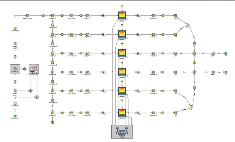
We have a Direct Injection Diesel Engine with 6 cylinders with an intercooler system. The main function of the intercooler is to cool the hot air coming out of the compressor. From the model we can see that we have only provided assumptions for inlet conditions for both Compressor Outlet and Turbine Inlet respectively.
Tutorial 7
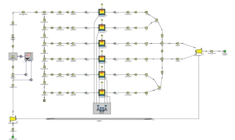
The model here has compressor and turbine attached to it. We are provided with twin entries to the turbine which is a representation of a twin scroll turbine conguration. We are provided with both compressor and turbine maps by the manufacturer which helps in eciently modelling them using GT Power.
Plot operating points on compressor and turbine maps:
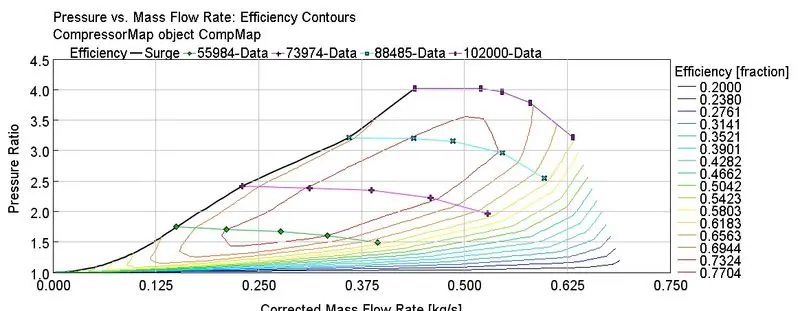
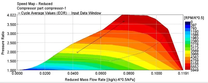
Compressor Map
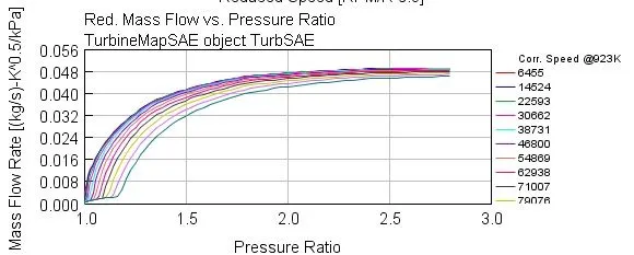
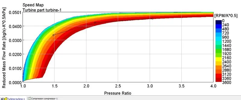
Turbine Map
In which application Variable Geometry Turbine is beneficial?
Variable Turbine Geometry technology is the next generation in turbocharger technology where the turbo uses variable vanes to control exhaust ow against the turbine blades. See, the problem with the turbocharger that we’ve all come to know and love is that big turbos do not work well at slow engine speeds, while small turbos are fast to spool but run out of steam pretty quick. So how do VTG turbos solve this problem?
A Variable Turbine Geometry turbocharger is also known as a variable geometry turbocharger (VGT), or a Variable Nozzle Turbine (VNT). A turbocharger equipped with Variable Turbine Geometry has little movable vanes which can direct exhaust ow onto the turbine blades. The vane angles are adjusted via an actuator. The angle of the vanes varies throughout the engine RPM range to optimize turbine behaviour
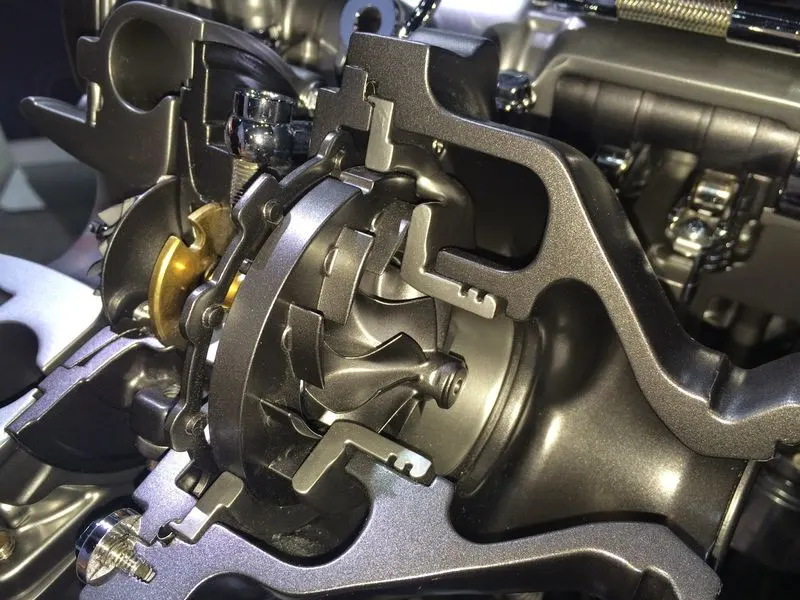
In the 3D illustration above, you can see the vanes in an angle which is almost closed. The highlighted variable vanes shown in diagram. This position is optimized for low engine RPM speeds, pre-boost. In this cut-through image, the direction of exhaust ow when the variable vanes are in an almost closed angle is shown. The narrow passage of which the exhaust gas has to ow through accelerates the exhaust gas towards the turbine blades, making them spin faster. The angle of the vanes also directs the gas to hit the blades at the proper angle. Variable Turbine Geometry has been used extensively in turbodiesel engines since the 1990s. It is most commonly used in a passenger car to reduce the turbo lag and to make driving comfortable, but it has never been on a production petrol turbocharged car before until the new Type 997 Porsche 911 Turbo. This is because petrol engine exhaust gases are a lot hotter than diesel engine exhaust gas, so generally the material used to make VTG turbos could not stand this heat. The 997 and 911 turbo use a BorgWarner VTG turbocharger which uses special materials derived from aerospace technology, hence solving the temperature problem.
BENIFICIAL OF VGT:
Compared with fixed geometry turbochargers, variable geometry turbochargers are designed to.
- Increase intake air boost pressure at low engine speed.
- Improve the response time of the turbocharger during transient engine operation phases.
- Increase the availability of the maximum engine torque.
- Prevent over-boosting at high engine speed reduce exhaust gas emissions and improve fuel economy is beneficial in passenger cars.
Explore example- Diesel VGT EGR and understand the modelling part:
The example 'Diesel_VGT_EGR' demonstrates several modelling concepts important for automotive diesel engines, including variable geometry turbine, boost control, intercooler, EGR circuit with cooler and EGR rate control, injection limiting for smoke control, and exhaust after treatment device modelling (geometry only, no chemistry).
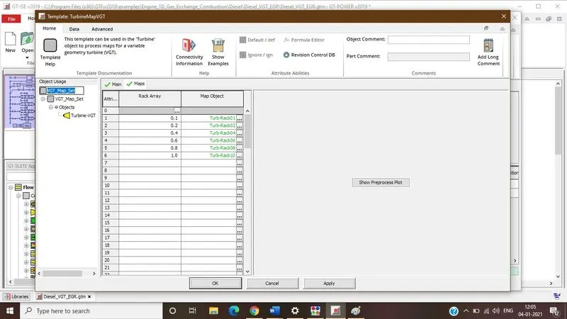
Taking look at VGT in the turbine templet the different rack position is given to define VGT.
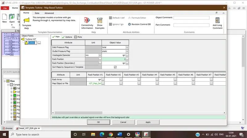
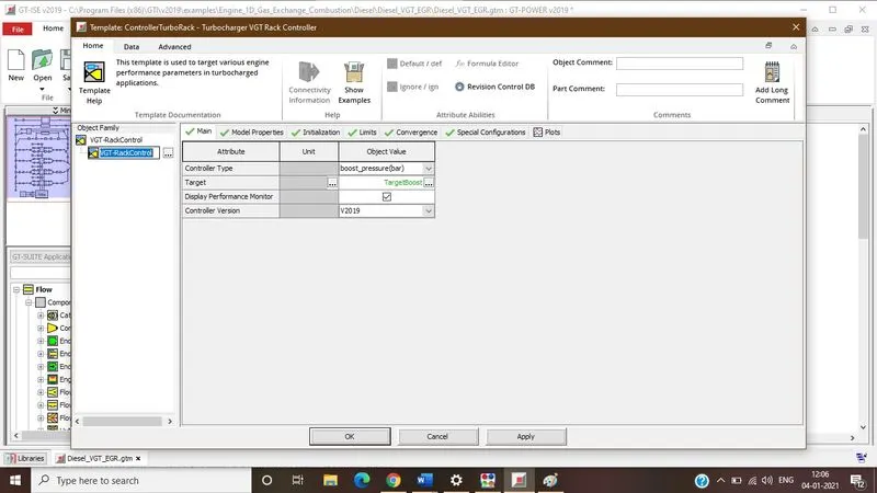
In the VGT controller boost pressure is controlled
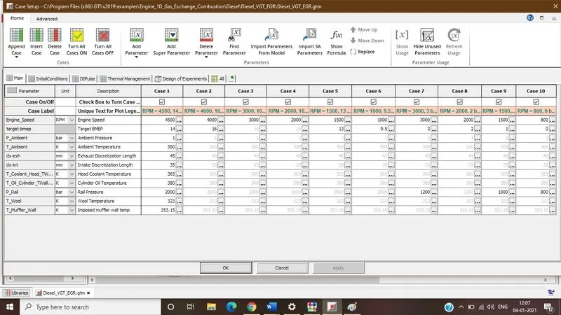
The model is run with the 10 cases with different target BMEP & engine speed
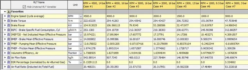
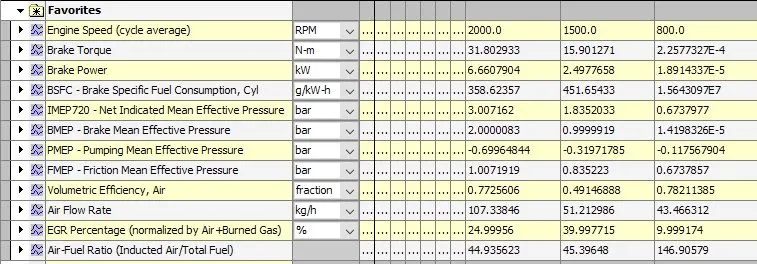
- Comparing case 1 and 2 results - This case contains a high BMEP and a low rpm and a low BMEP and a high rpm respectively. In such cases the power generated by engine is same.
- The brake power for case 1 (with 4500 rpm speed and 14 bar BMEP) and case 2 (with 4000 rpm and 16 bar BMEP target) values are very close to each other. But if we see BSFC's then for case 1 is higher. EGR % is very less for case 1 and for case 2 its zero this is due to engine is operated at low or no pressure difference.
- Comparing case 2 3 4 which are operated with 4000, 3000 & 2000 rpm and targeting 16 bar BMEP. From all of the 3 cases we can see power, BSFCs, A/F varies with the speed but torques remains same for all of 3 cases. So, it shows that torque is a function of BMEP. And in all these cases there is no EGR happens.
- Comparing case 3 4 5 with case 7 8 9 respectively so they are operated with same speed but cases 3 4 5 has high BMEP targets and cases 7 8 9 has lower BMEP target.
- From the above case we can see that lower BMEP generates lower torque and Power as torque is a function of BMEP and power is a function of torque and engine speed. BSFCs are high for low BMEP cases and vice versa. At lower BMEP the engine operating pressure difference is greater so the EGR circulation is possible.
- As engine rpm reduces there is reduction of overall pressure ratio & output pressure. At low engine speed there is increase in intake air boost pressure.
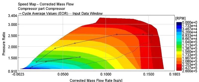
- From above compressor map we can see that as point procced from 1 to 10 case, there is reduction in mass flow rate & pressure ratio as the engine speed it reduces.
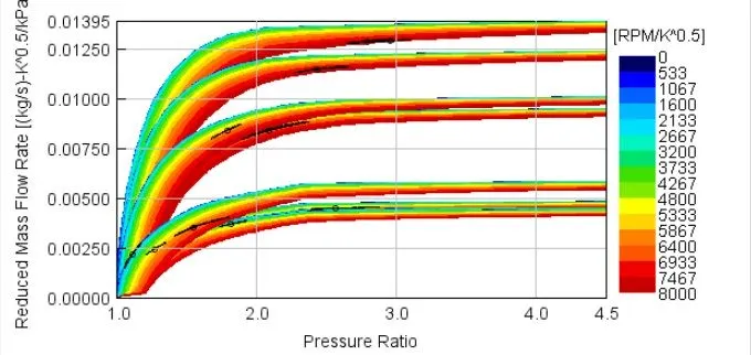
- Above Turbine map shows that turbine is operated with a different mas ow rates and different pressure ratio and all of the 10-case reading is shown in above turbine map and it shows that using different rack positions we can define VGT and VGT is able to controls variable exhaust flow.
4. Conclusion:
- Turbocharger is manly use for increase the output power of vehicle. It has different type & it uses as per operating condition & used in different type of vehicle.
- Altitude is affected on engine performance so by providing correct mass of fuel, we can obtain better output power at higher altitude.
- By use of Wastegate turbocharger we can set the pressure ratio of turbocharger & also we can avoid the mechanical damage.
- Variable geometry turbocharger uses variable vanes to control exhaust ow against the turbine blades. VGT is useful for operate different altitude as well as its useful for to get quick acceleration there is use.