Assignment 6
Aim- Crash simulation using Hypermesh/Hypercrash/Radioss over a CAR frontal BIW structure.
Objective-
1- Check the unit system (Kg, mm, ms or Mg, mm, s )
2- Create an appropriate interface with the recommended parameter, make sure there is no penetration and intersection.
3- Create a rigid wall as per requirment.
4- Add mass for proper COG.
5- Giving initial velocity to the vehicle.
6- Use the model checker to ensure there is no error.
7- Create the Timestep ( 0.5 to 0.1 ) and run time to 80ms.
8- Run the simulation and plot the required results.
Introduction-
Crashworthiness is a term that describes a vehicle’s ability to protect its occupants during a collision. This means that the airbags and tires as well as the structure of the car must all prevent serious personal injuries in the event of a crash. Manufacturers must test all vehicles for crashworthiness before they enter the marketplace. However, car defects can result in a vehicle that does not provide adequate protection from the force of a collision. If you sustain injuries in a car accident due to the vehicle’s lack of crashworthiness, then you may have a claim against the vehicle’s manufacturer.
Crashworthiness concerns the safety of a vehicle during a car accident, not crash prevention. Product liability law requires that all manufacturers ensure their products are safe for all reasonable consumer use. Since millions of car crashes happen every year, it is reasonable for vehicle manufacturers to ensure occupant safety in their automobiles even during a wreck.
Body In White (BIW)-
Body in white is the stage in automobile manufacturing in which a car body's frame has been joined together, that is before painting and before the motor, chassis sub-assemblies, or trim (glass, door locks/handles, seats, upholstery, electronics, etc.) have been integrated into the structure. Assembly involves different techniques such as welding (spot, MIG/MAG), riveting, clinching, bonding, and laser brazing.
The term derives from manufacturing practices before steel unibody monocoques — when automobile bodies were made by outside firms on a separate chassis with an engine, suspension, and fenders attached.The manufacturers built or purchased wooden bodies (with thin, non-structural metal sheets on the outside) to bolt onto the frame. The bodies were painted white prior to the final color.
Frontal Crash Test-
The frontal impact is performed at 64kph (40mph), the car crashes into a deformable barrier with 40% of its width front on the driver side (offset). Readings taken from the crash test dummies are used to assess protection given to adult occupants in the front seat. Each car tested is subjected to an offset impact into an immovable block fitted with a deformable aluminium honeycomb face. This impact is intended to replicate the effect caused in the car when crashing 55km/h 50% offset frontal crash with a similar mass car. As most frontal crashes involve only part of each car's front, the test is offset to replicate a half-width frontal impact between two cars. In the test, this is replicated by having 40 percent of the width of the car crashing into the aluminium deformable barrier. This represents the most frequent type of road crash, resulting in serious or fatal injury. The barrier face is deformable to represent the deformable nature of the cars. Two adult dummies are placed representing average size men in the driver's seat and front passenger and two children, aged 18 months and 3 years old, on child restraint systems are placed in the rear seat. Contact between the occupant and hard and intruding parts of the passenger compartment is the main cause of serious and fatal injuries for restrained adult car occupants. The test speed of 64 km/h represents a car to car collision with each car travelling at around 55 km/h and crashing 50% of their width. The difference in speed is due to the energy absorbed by the deformable face. Accident research has shown that this impact speed covers a significant proportion of serious and fatal accidents. By preventing intrusion, the chances of the occupant impacting the car's interior are minimised with space remaining for the restraint system to operate effectively. The steering wheel and dashboard-mounted airbags are an important part of the driver's restraint system. Latin NCAP encourages designs where the driver's and passenger’s heads and chests are given stable support from the airbags and where the head does not bottom out'. For a restrained occupant, the deceleration forces generated during the crash are transmitted to the occupant through the restraint system. Latin NCAP encourages the adoption of performance-based regulations for seatbelts with pre-tensioners, load limiters, and dual-stage airbags, to help attenuate the forces transmitted to the occupant. In most cars, the restraint system is unable to prevent the knees of the front seat occupants from impacting the facial. Latin NCAP encourages the removal of hazardous structures from the areas that the knees can impact. High forces on the knee can cause injury to the knee itself and can be transmitted up the thigh to the hip joint and pelvis. These load-bearing parts of the skeleton are susceptible to severe, long term, disabling injuries. In order to minimise injuries, Latin NCAP encourages intrusion reduction of the footwell area and greater control of foot pedals displacement
Procedure-
A- Unit check-
First, we need to check the unit for the model, it should be matched with the software in which we going to perform the analysis, we can check the unit from a hyper crush or we can also check it from the input .RAD file.

B- Center Of Gravity-
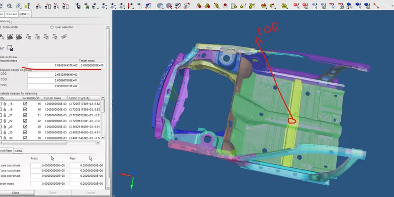
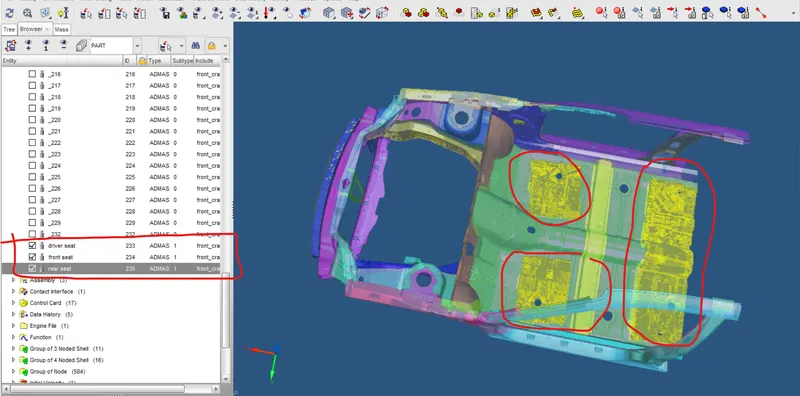
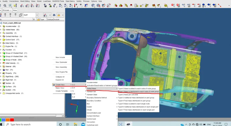
The model we get here is not the full model, so we need to match the COG so for that we need to increase the vehicle mass, here we added the mass in HYpercrash so that we can get proper COG. We can see that the model we were given has 187kg mass and the full model has 700kg so we need to balance the mass so that we can achieve a better COG.
C- Contact Interface and Penetration Check-
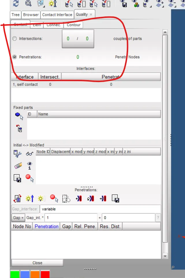
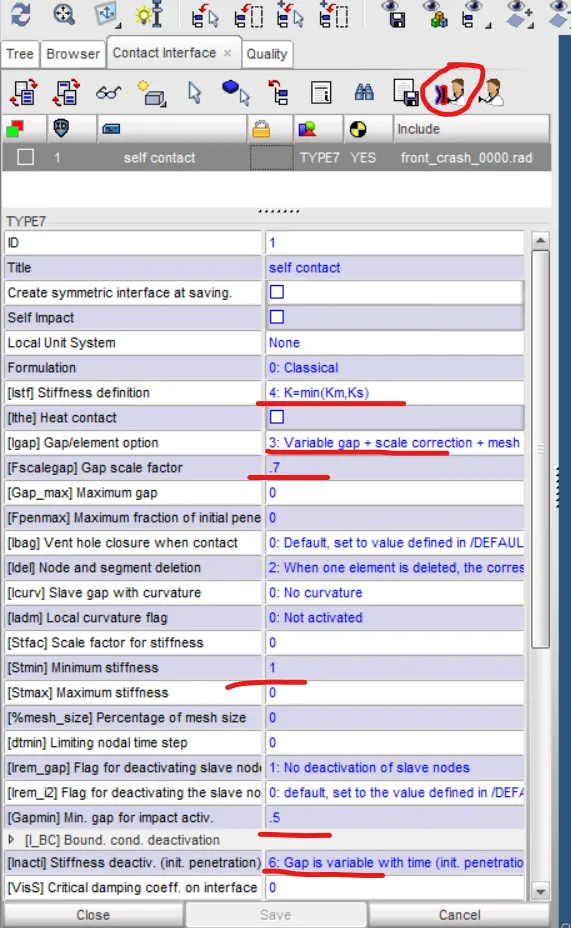
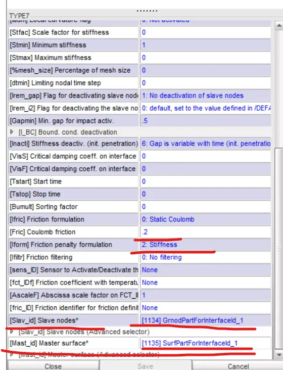
After the mass balancing we moved for interface assignment, for that we use contact interface with Type-7 interface, the reason behind using type-7 is its frequently used interface for elastoplastic material, and the reason why we giving the contact interface for the model so that they can not collapse with each other and behave like rigid and not collide to each other.After giving the interface we went to check the intersection and penetration between the node/element, if there is any penetration then we need to clear it.
D- Initial Velocity-
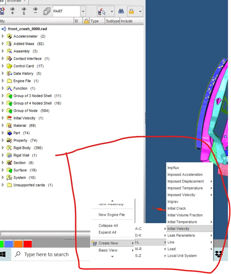
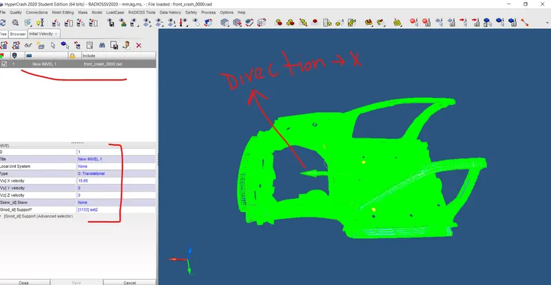
To impact with the wall we need to give the vehicle some speed, here we gave 15.65mph as initial velocity to the model so that it can impact on the wall, with appropriate direction ( in the direction of the wall ).
E- Acceleration-
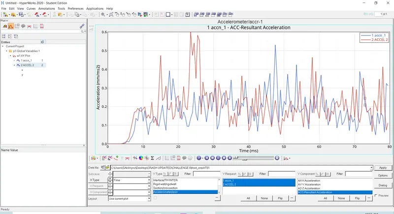
Here we assign the accelerometer to measure the acceleration of the nodes during the collision.
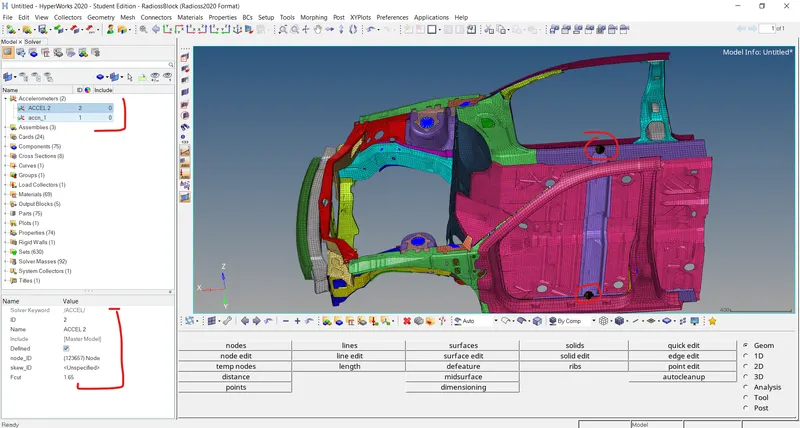
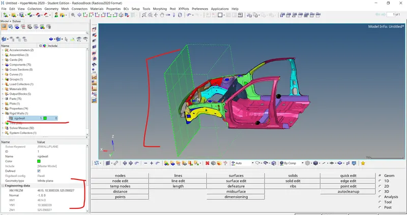
F- Rigid Wall-
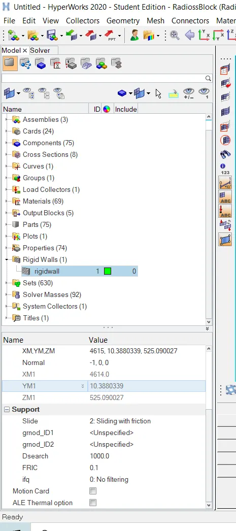
So to crash test we need to create a rigid wall in front of the vehicle, here we used a rigid wall as an impactor with appropriate input with some distance.
G- Contact Forces-
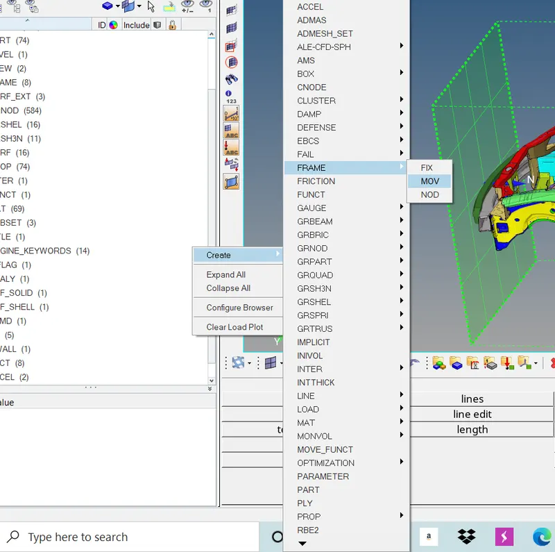
To measure the forces on the BIW structure we need to assign some input to the model to measure the forces on the structure for that we first created FRAME ---SET---CROSS-SECTION using hypermesh.
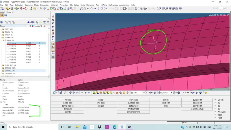
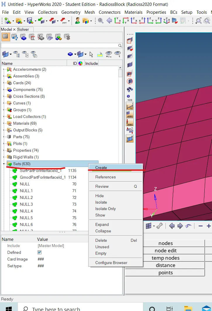
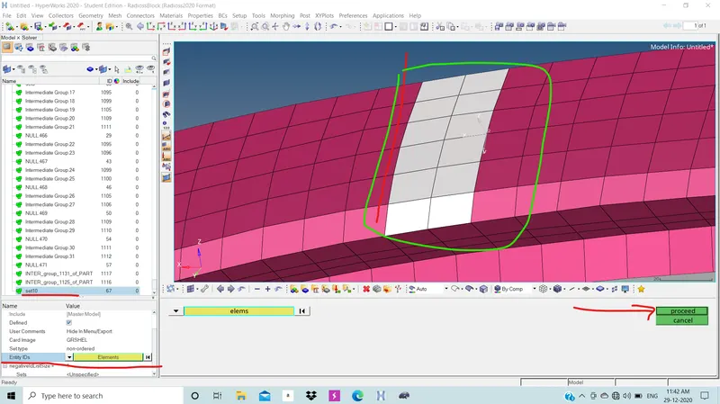
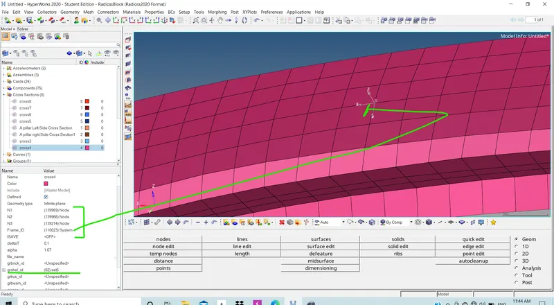
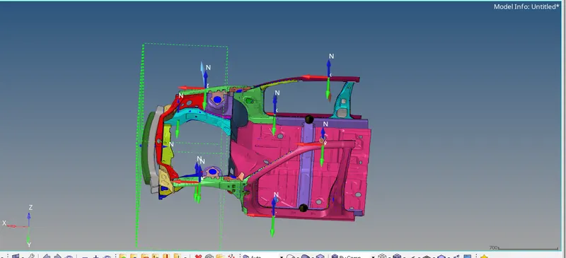
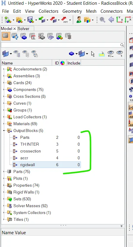
H- Output Request-
To see all these parameters we need to give an output request in simulation, so created an output request for all we need to see in the result in post-processing.
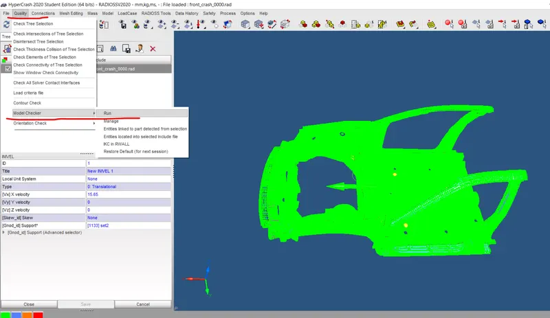
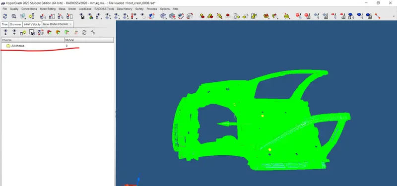
I- Model Checker-
In the last we need to check the model should have errors.
Results-
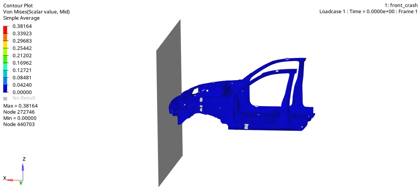
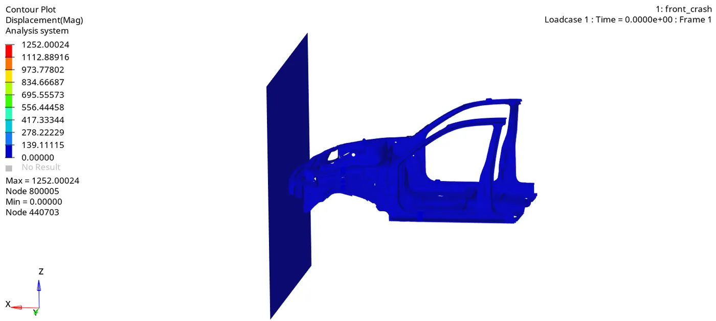
These are the contour plot for von misses stress and displacement which are plotted using Hyper View. Here we can see vehicles moving at 15.65mph and strikes with the wall the maximum stress developed is 0.38164 N/mm2 at 80ms .
Energy Capturing-
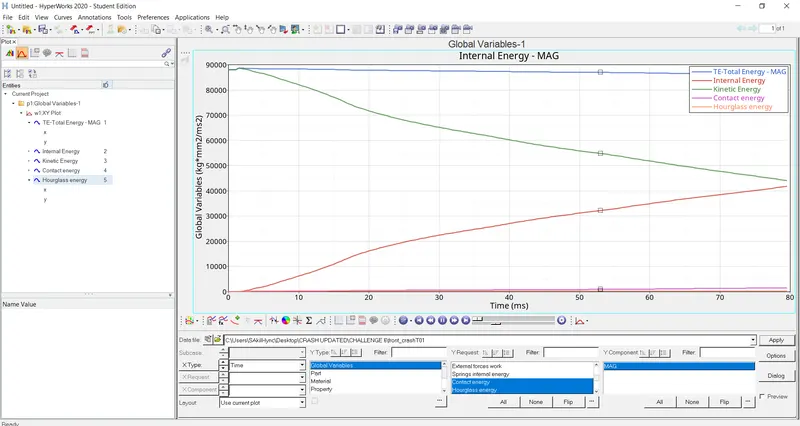
Here we can see in the initial stage some energies are increasing due to strikes and some increasing, so the total energy remains constant.
Acceleration-
These graphs showing the acceleration.
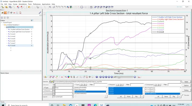
Cross-Section Forces-
These are the forces that induce at various places in the BIW structure as we assign the cross-section.
Conclusion-
1- Model has been imported in the Hypermesh and Hypercrash.
2- Model gas checked for error and penetration also for any free parts.
3- Added mass located with proper COG.
4- Simulation Terminated normally with negative error with 8001 no. of cycles and time elapsed is near to 4000s.