Assignment 6
AIM:
To do "FRONTAL CRASH ANALYSIS" for the given "BIW" car model using "HYPERMESH AND HYPERCRASH".
OBJECTIVE:
FRONTAL CRASH BIW:
- To Check unit system and either follow[Mg mm s] or [Kg mm ms].
- To Create appropriate interface ,friction 0.2 and recommended parameters.
- To Make sure of no penetrations and intersection.
- To Correct rigid bodies if any issues.
- To Create rigid wall with friction 0.1.
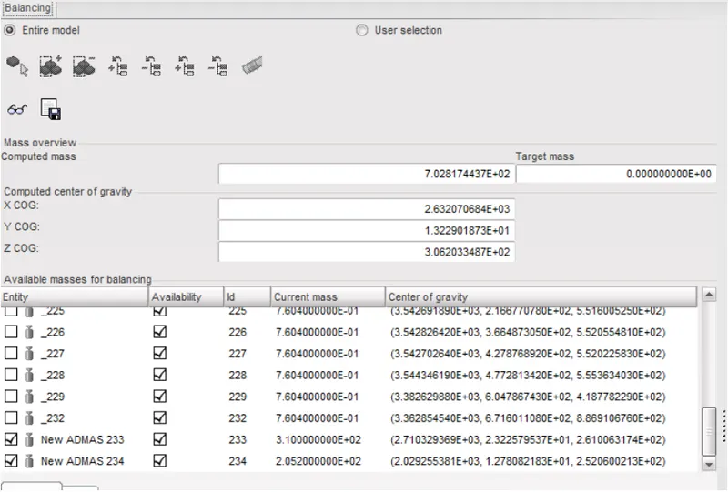
- To Compare the model weight with the full scale 300k nodes model and use added masses to reach target weight 700kg while getting CG about the required range.
- To give Initial velocity of 35 mph.
- To Use model checker to ensure good quality.
- Time-step to be 0.5 to 0.1 microseconds.
- Run time to be 80 ms.
OUTPUT REQUESTS:
- Sectional force in the rails at location of indicated node 174247.
- Axial force received on the rails from bumper.
- Shotgun cross sectional forces.
- A pillar cross section.
- Acceleration curve received on the accelerometer at base of B pillar (on B pillar rocker).
- Intrusions on the dash wall 66695,66244
PROCEDURE:
IN FRONTAL CRASH BIW:
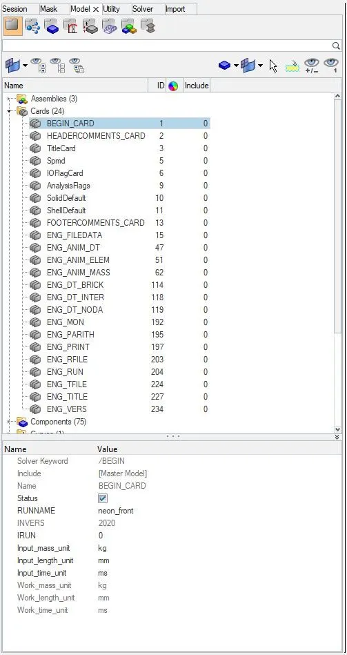
1) WE HAVE TO CHECK "UNIT SYSTEM" AND WE HAVE FOLLOWED [Kg mm ms] AS SHOWN BELOW:
WE SHOULD ALSO CHECK FOR DENSITY AND YOUNG'S MODULUS OF THE COMPONENT'S MATERIAL:
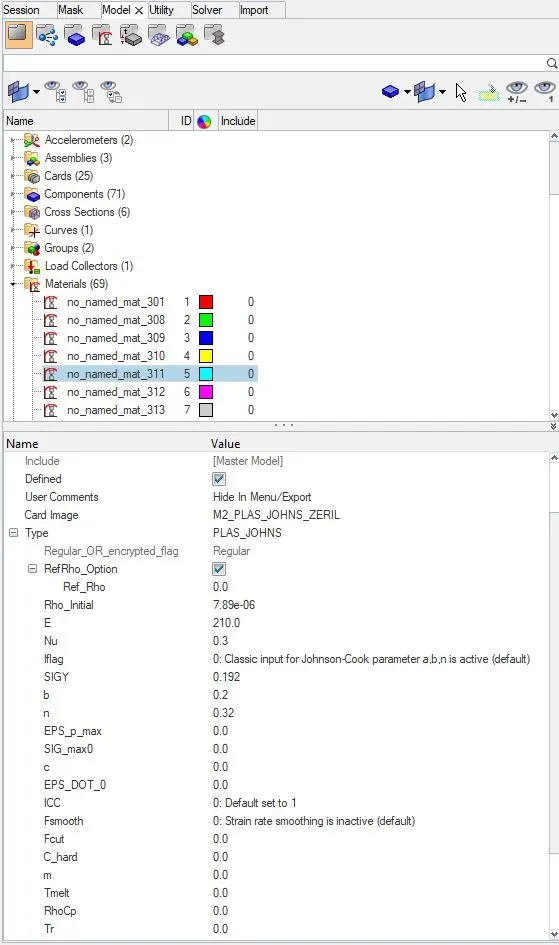
BY THE ABOVE IMAGE WE KNOW THAT:
DENSITY : 7.89E-06 `(Kg)/(mm^3)`
YOUNG'S MODULUS : 210GPA
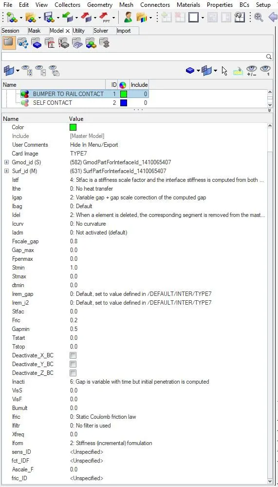
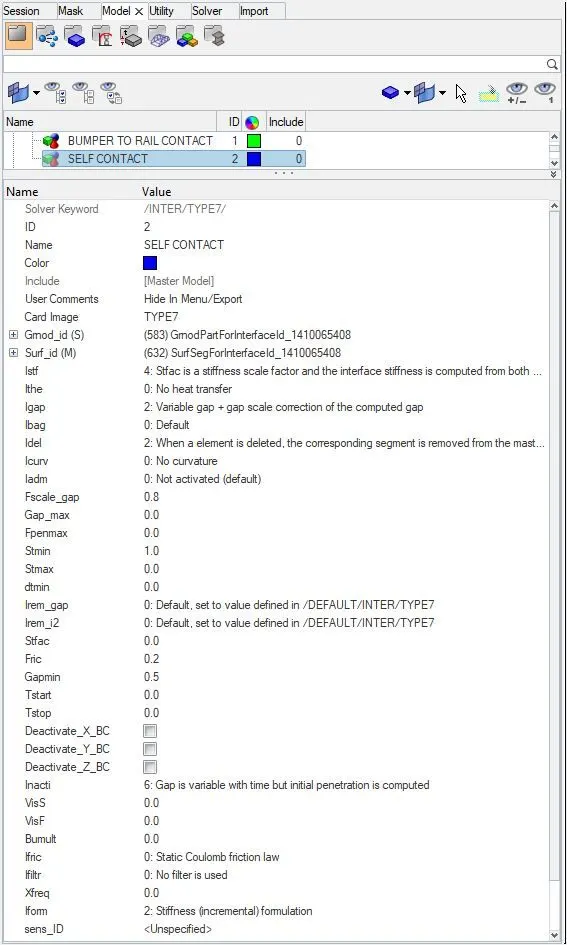
2) WE HAVE TO CREATE APPROPRIATE INTERFACE FOR THE GIVEN CAR COMPONENT WITH ALL THE RECOMMENDED PARAMETERS AS SHOWN BELOW:
CONTACT BETWEEN "BUMPER" AND "RAIL" OF THE CAR BY USING "TYPE-7 INTERFACE" FOR DETERMINING "AXIAL FORCE RECEIVED ON RAILS FROM BUMPER:
SELF CONTACT OF THE CAR BY USING "TYPE-7 INTERFACE":
3) WE SHOULD MAKE SURE OF NO "PENETRATION" AND "INTERSECTION" OF SLAVE NODE INTO MASTER SEGMENT:
IN HYPERMESH:
GOTO: "Tools" > "Penetration Check" > "Then hit CHECK"
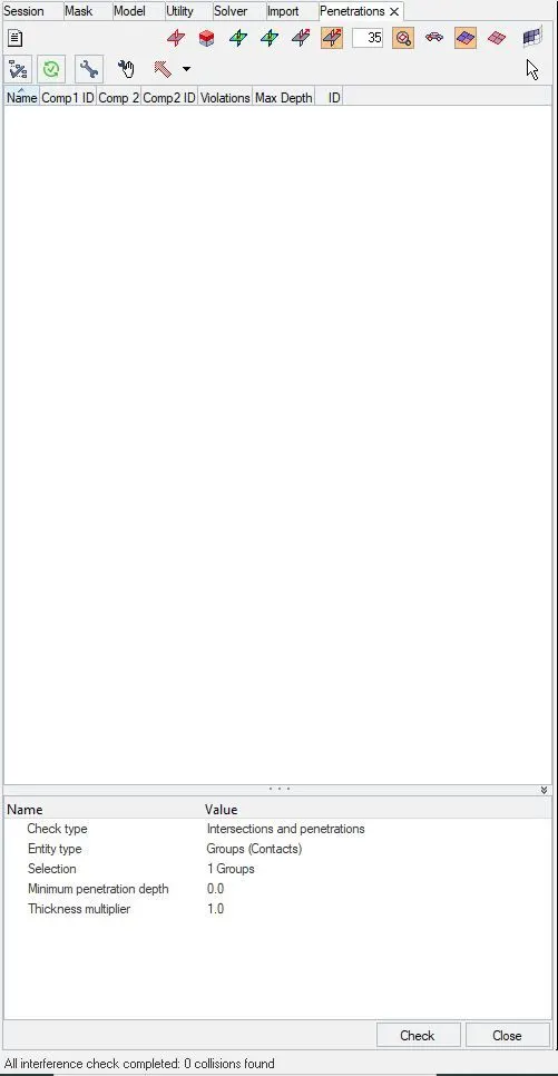
IN HYPERCRASH:
GOTO = "Quality" > "Check all solver contact interfaces"
A) PENETRATION CHECK:
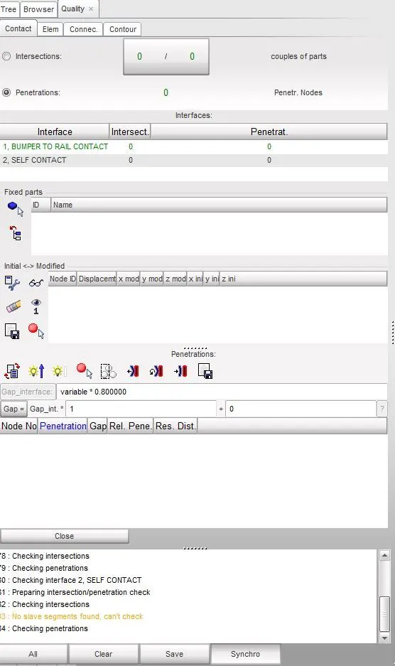
From the above image we can say that there are no penetrations happening in the given model.
B)INTERSECTION CHECK:
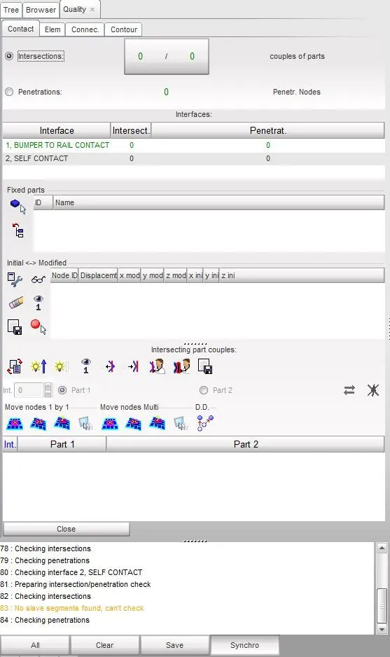
So, as per the above image, both "INTERSECTION" and "PENETRATION" are "0".
4) WE HAVE TO CORRECT RIGID BODIES IF THERE ARE ANY ISSUES:
IN HYPERCRASH:
GOTO: "Quality" > "Check connectivity of tree selection"
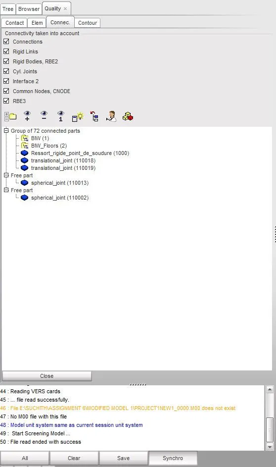
IN HYPERMESH:
GOTO: "Tools" > "Find Connectivity" > "Check"
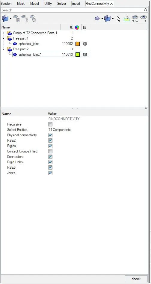
WE HAVE TO DELETE ALL THESE UNWANTED FREE PARTS IN COMPONENTS, THEY ARE "SPHERICAL JOINTS 110002 AND 110013"
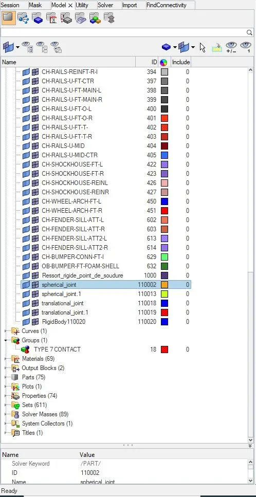
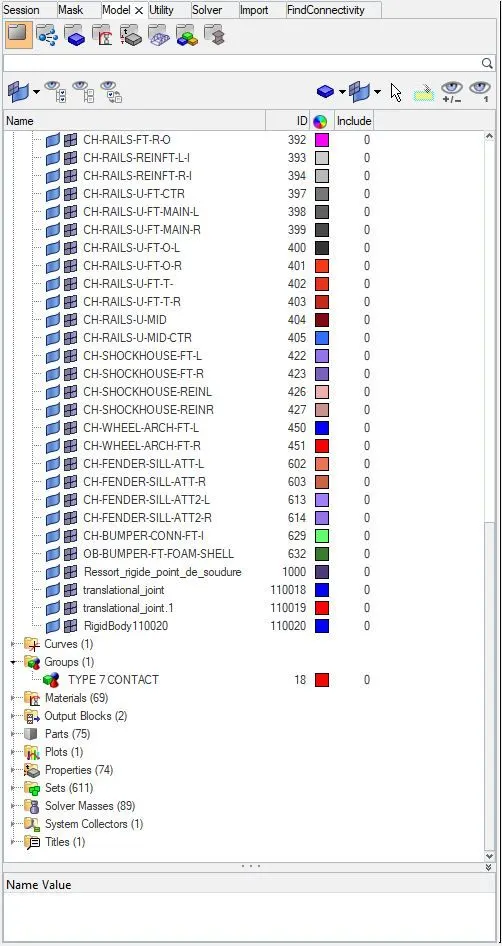
AFTER DELETING UNWANTED FREE PARTS:
5) CREATING RIGID WALL WITH FRICTION 0.1
IN HYPERMESH:
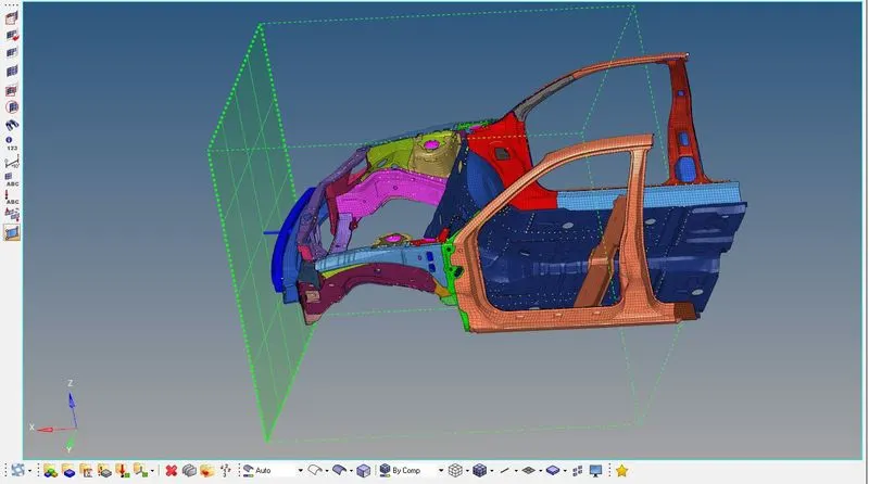
GOTO: "View" > "Browser" > "Hypermesh" > "Solver" > "Right click and create new RIGID WALL" > "In GEOMETRY TYPE = INFINITE PLANE" > "With appropriate D_Search", as shown below:
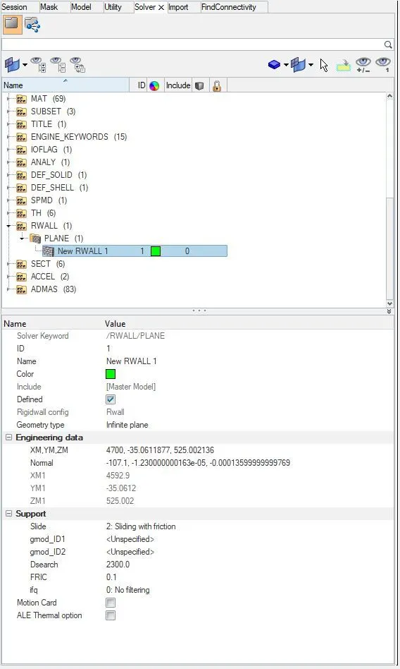
IMAGE OF RIGID WALL IN FRONT OF THE CAR:
6) WE HAVE TO USE "ADDED MASSES" TO REACH TARGET WEIGHT OF "700KG" WHILE GETTING "CENTER OF GRAVITY" ABOUT THE REQUIRED RANGE AS SHOWN BELOW:
- We can't view "C.G" point in "HYPERMESH"
- So we use "HYPERCRASH" to view "C.G" point
- To view "C.G" point in "HYPERCRASH", we have to GOTO: "Mass" > "Balancing" > "Click on the icon which represents View COG point".
INITIAL MASS BEFORE ADDING ANY MASS:
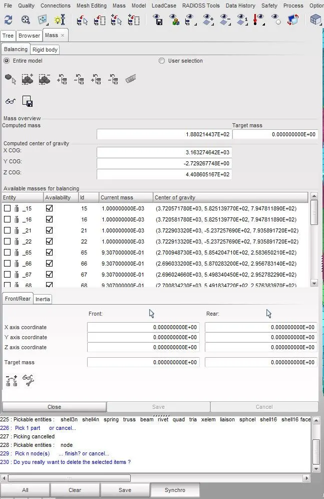
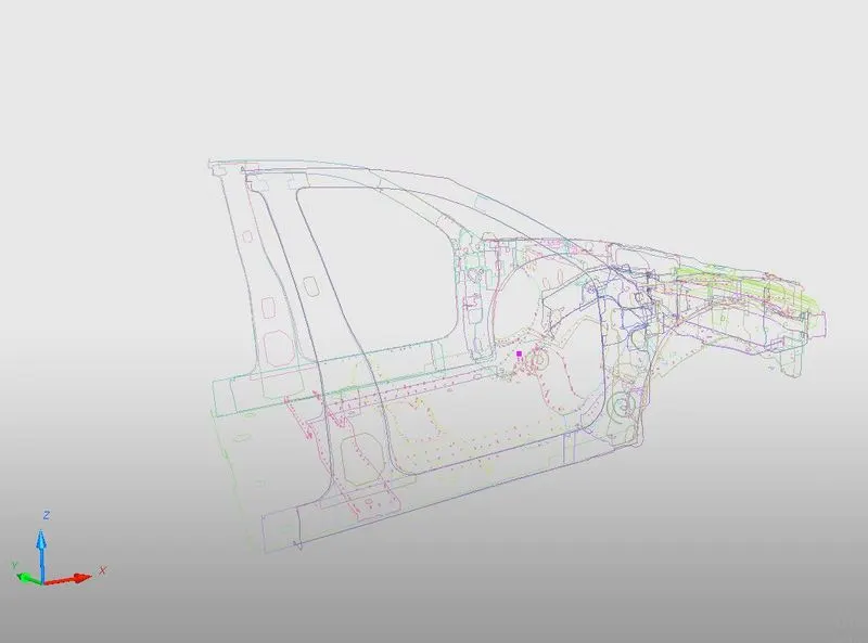
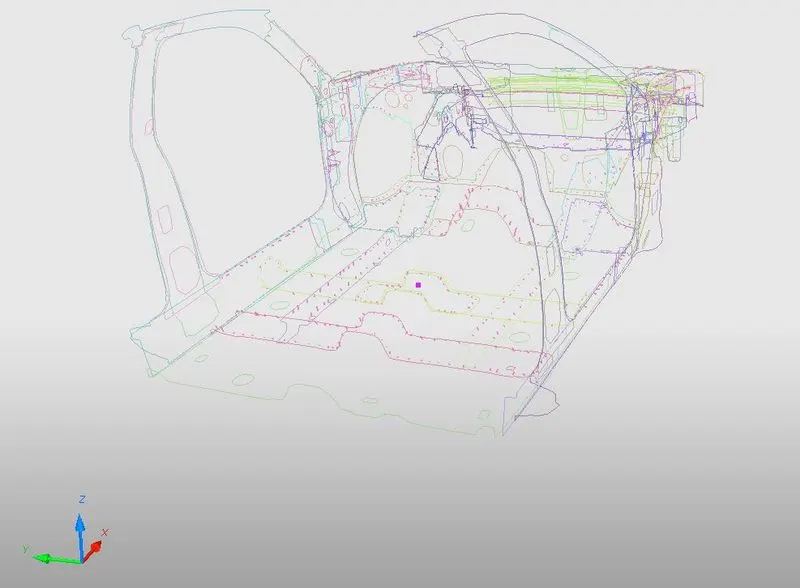
COG POINT BEFORE ADDING MASSES IS AS SHOWN BELOW: "COG POINT IS REPRESENTED BY A PINK POINT IN THE MODEL"
NOW WE HAVE TO MOVE THIS "COG" POINT TO THE CENTER OF THE CAR BY ADDING MASSES ON THE FLOOR OF THE CAR AS SHOWN BELOW:
GOTO: "Browser" > "Right click" > "Create new" > "Added Mass"
ADDED MASS ON LEFT SIDE OF THE CAR AS SHOWN BELOW:
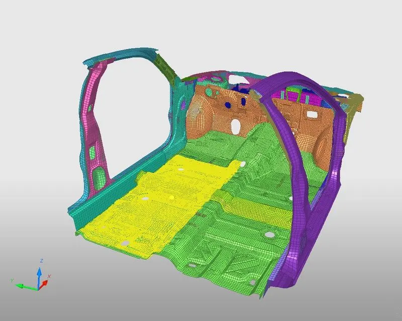
ADDED MASS ON RIGHT SIDE OF THE CAR AS SHOWN BELOW:
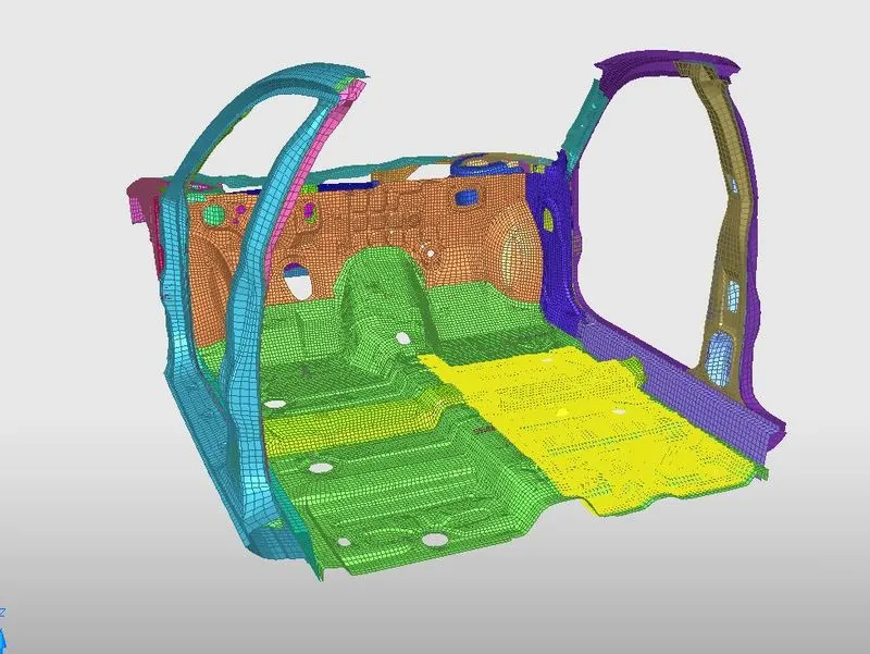
"COG" POINT AFTER ADDING MASSES AS SHOWN BELOW: "COG POINT IS REPRESENTED BY A PINK POINT IN THE MODEL"
TARGET MASS OF 700KG AS SHOWN BELOW:
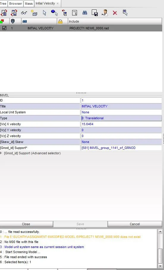
7) WE HAVE TO ASSIGN "INITIAL VELOCITY" TO CAR MODEL, AS SHOWN BELOW:
GIVEN: INITIAL VELOCITY OF "35MPH" OR "15.6464MM/MS"
IN HYPERCRASH:
GOTO: "Browser" > "Right click" > "Create new" > "Initial Velocity"
INITIAL VELOCITY IS ADDED TO THE CAR MODEL AS SHOWN BELOW WITH GIVEN PARAMETERS:
MODEL IMAGE AFTER IMPLYING INTIAL VELOCITY:
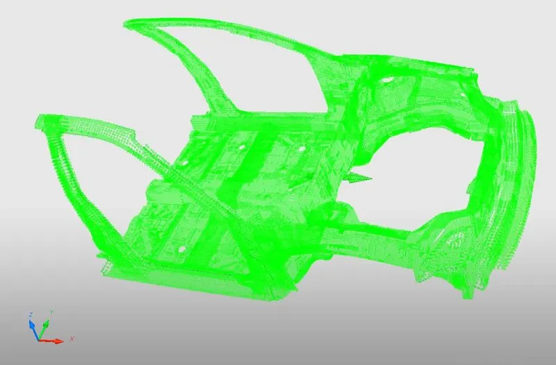
8) WE SHOULD USE MODEL CHECKER TO ENSURE GOOD QUALITY:
IN HYPERMESH:
GOTO: "Tools" > "Model Checker" > "RADIOSS BLOCK"
- But we did'nt find any errors like "TRANSLATIONAL JOINTS", (usually when we do model checking in "HYPERMESH", errors are not detected and recognised properly as we see in "HYPERCRASH")
IN HYPERCRASH:
GOTO: "Quality" > "Model Checker" > "RUN"
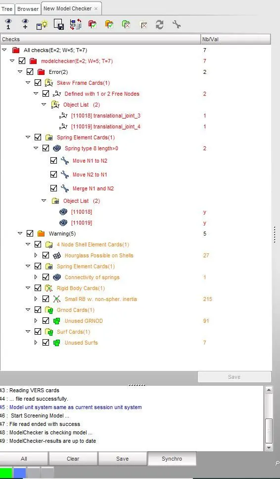
- Here we found "TRANSLATIONAL JOINTS" as errors when we did model checking.
- After finding errors, we have to goto "Browser" > "Parts", and then DELETE all the "TRANSLATIONAL JOINTS".
- In the below image, 110018 and 110019 are the "TRANSLATIONAL JOINTS".
- Right now all warnings are neglected.
AFTER RUNNING MODEL CHECKER, ERRORS ARE DETECTED AS SHOWN BELOW:
9) TIME-STEP TO BE BETWEEN :0.5 to 0.1 microseconds
IN HYPERMESH:
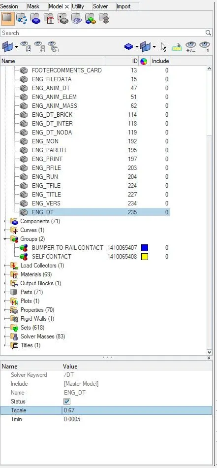
GOTO: "Solver" > "Right click" > "Create" > "ENGINE KEYWORDS" > "DT"
- "Tscale" = 0.67
- "Tmin" = 0.0005ms (Here we have used 0.5 microseconds)
IN HYPERCRASH:
GOTO: "Browser" > "Create new" > "Control cards" > "ENGINE" > "DT"
- "Tscale" = 0.67
- "Tmin" = 0.0005ms (Here we have used 0.5 microseconds)
THE BELOW IMAGE REPRESENTS THE TIME-STEP IN "HYPERMESH":
10) RUN TIME SHOULD BE "80 MILLI SECONDS"
IN HYPERMESH:
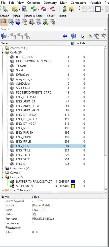
GOTO: "Model" > "Cards" > "ENG_RUN" > "Tstop = 80"
IN HYPERCRASH:
GOTO: "Browser" > "Right click" > "Create new" > "Control cards" > "ENGINE" > "RUN" > "[DT_STOP] Final time for run = 80"
THE BELOW IMAGE REPRESENTS THE "RUN TIME" IN "HYPERMESH":
OUTPUT REQUESTS: ALL DONE IN "HYPERCRASH"
PROCEDURE FOR OBTAINING SECTIONAL FORCE AT A PARTICULAR SECTION USING MOVING FRAMES IS AS EXPLAINED BELOW: "IN HYPERCRASH"
- For Sectional forces we have to create a new "SECTION" at that node.
- To do that, GOTO: "Browser" > "Right click" > "Sections" > "Default section".
- Another method To do that is, GOTO: "Data History" > "Sections" > "Sections" > "Click on the icon which represents Create new object" > "Default section".
- Mode of Creation = "Basic all Fields".
- [Dt] Time step for saving the data = 0.1 milli seconds.
- [alpha] Filtering coefficient = 0.67.
- [Frame_ID] Frame = "Right click" > "Create frame".
- And in [Frame_ID] TYPE = MOV: Moving frame.
- Here we have to select "3 NODES" : N1, N2 AND N3.
- Where N1 and N2 DEFINE: X-AXIS.
- The 3rd node N3 DEFINE: Y-AXIS.
- Note that Z-AXIS should always be in parallel with [FN] FORCE or "OPPOSITE" to the direction of the moving component.
- [Iframe] Skew center : "0: center of the local skew".
- Now we should copy all the "NODE ID" of N1, N2 AND N3 to [node_ID1], [node_ID2] and [node_ID3] for representing [FN] and sections.
- [node_ID1] Node 1 (to define tail of local X-axis of the section).
- [node_ID2] Node 2 (to define head of local X-axis of the section).
- [node_ID3] Node 3 (to define local plane XY of the section).
- In [grshel_ID] Shell group identifier : Select all the "SHELLS" in that particular section where we have created the "MOVING FRAME".
- In [grtrianID] Triangle group identifier : Select all the "TRIAS" in that particular section where we have created the "MOVING FRAME".
- Then click on "SAVE".
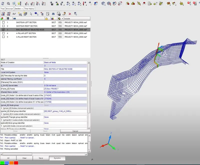
1) WE SHOULD CREATE A SECTIONAL FORCE IN "RAILS" AT LOCATION OF THE INDICATED NODE "174247", THIS NODE IS ON "LEFT RAIL SECTION":
- Using the above procedure, we'll obtain the "SECTIONAL FORCE" at a particular section using "MOVING FRAMES", as shown below.
A] "LEFT RAIL SECTION":
IMAGE 1: LOCATING THE GIVEN NODE ON THE COMPONENT USING "NODE_ID":
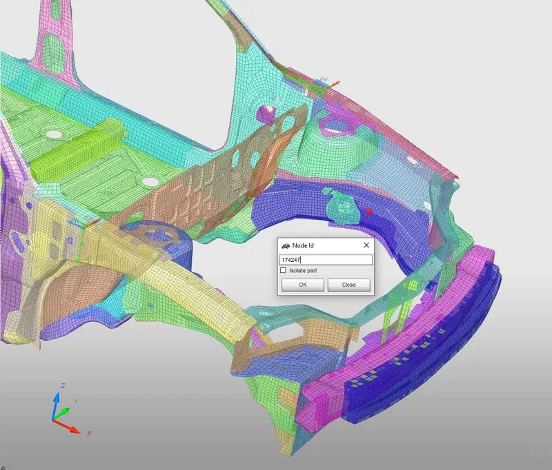
IMAGE 2: CREATING SECTION AT THE GIVEN "NODE_ID":
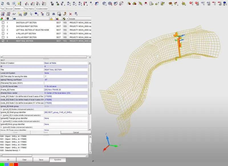
B] "RIGHT RAIL SECTION":
THE BELOW IMAGE REPRESENTS THE CREATION OF SECTION AT RIGHT RAIL SECTION:
2) AXIAL FORCE RECEIVED ON THE RAILS FROM BUMPER:
- For this we need to create new "TH" FILE, This can be created in "TH" (SOLVER) or in "OUTPUTBLOCKS" (MODEL).
- GOTO: "Solver" > "Create a new TH file", or
- GOTO: "Model" > "Create a new Output block".
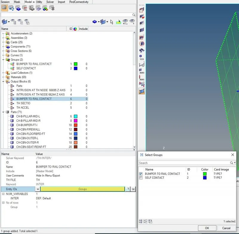
A] CREATING NEW OUTPUT BLOCK IN MODEL:
THE BELOW IMAGE REPRESENTS THE CREATION OF NEW "OUTPUT BLOCK" IN "MODEL" FOR AXIAL FORCE RECEIVED ON RAILS FROM BUMPER:
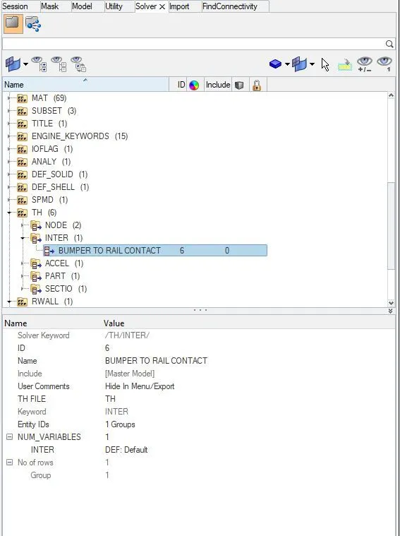
B] CREATING A NEW "TH FILE" IN "SOLVER":
- This "TH FILE" will be created as soon as we create a new "OUTPUT BLOCK" IN "MODEL", or we can come to "SOLVER" and create a new "TH" file, as shown in the below image:
3) WE SHOULD CREATE A SECTIONAL FORCE IN "SHOTGUN":
- Using the above procedure, we'll obtain the "SECTIONAL FORCE" at a particular section using "MOVING FRAMES", as shown below.
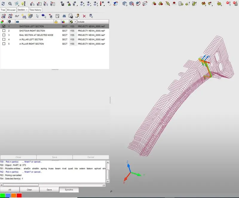
A] "SHOTGUN LEFT SECTION":
THE BELOW IMAGE REPRESENTS THE CREATION OF SECTION AT SHOTGUN LEFT SECTION:
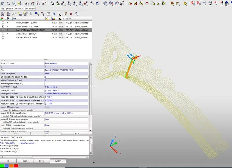
B] "SHOTGUN RIGHT SECTION":
THE BELOW IMAGE REPRESENTS THE CREATION OF SECTION AT SHOTGUN RIGHT SECTION:
4) WE SHOULD CREATE A SECTIONAL FORCE IN "A-PILLAR":
- Using the above procedure, we'll obtain the "SECTIONAL FORCE" at a particular section using "MOVING FRAMES", as shown below.
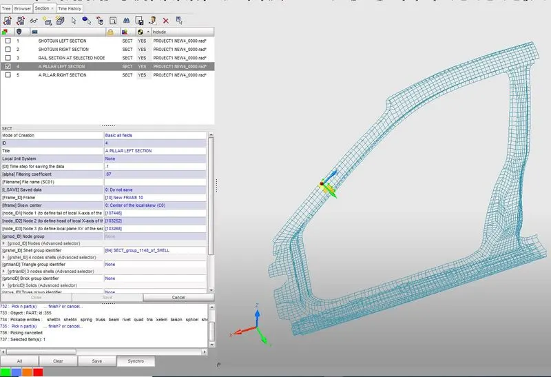
A] "A-PILLAR LEFT SECTION":
THE BELOW IMAGE REPRESENTS THE CREATION OF SECTION AT A-PILLAR LEFT SECTION:
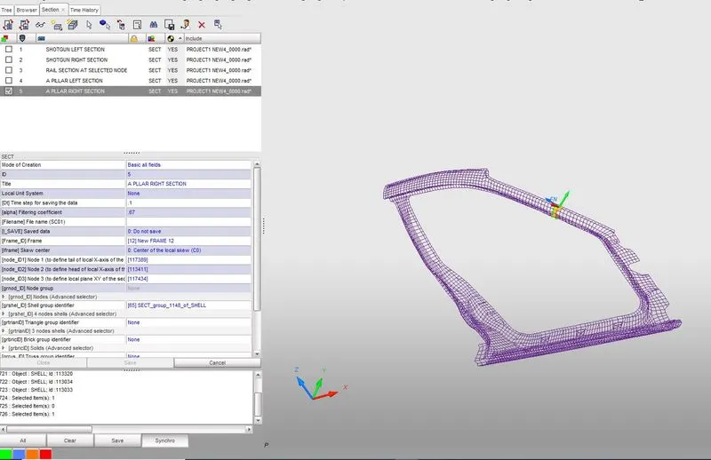
B] "A-PILLAR RIGHT SECTION":
THE BELOW IMAGE REPRESENTS THE CREATION OF SECTION AT A-PILLAR RIGHT SECTION:
PROCEDURE FOR PLACING AN ACCELEROMETER AT BASE OF "B-PILLAR" (ON B-PILLAR ROCKER): "HERE WE HAVE PLACED THE ACCELEROMETER IN HYPERCRASH"
IN HYPERMESH:
- GOTO: "Solver" > "Right click" > "Create new" > "Accelerometer" > "In [node_ID] Node*, select a particular node in the given model where acceleration needs to be calculated".
- GOTO: "Model" > "Output blocks" > "Right click" > "Create new" > "In ENTITY_ID, select ACCELEROMETER" > "So now we can get that output when we are ploting the graph".
IN HYPERCRASH:
- GOTO: "Data history" > "Accelerometer" > "In [node_ID] Node*, right click and select 'Pick in graphics', and select the node where we need to place the accelerometer".
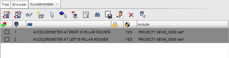
- IN HYPERCRASH, for obtaining the Acceleration graph, we need to select "YES" on the accelerometer icon at the top, there is no need to create a seperate output block as we did in HYPERMESH, this is shown in the below snap:
5) WE SHOULD PLACE AN ACCELEROMETER AT "BASE OF B-PILLAR ROCKER":
- Using the above procedure, we'll obtain the "ACCELERATION" at a particular "NODE" where we place an "ACCELEROMETER", as shown below.
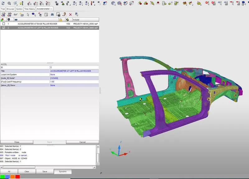
A] "LEFT B-PILLAR ROCKER"
THE BELOW IMAGE REPRESENTS THE PLACING OF ACCELEROMETER AT "BASE OF LEFT B-PILLAR ROCKER":
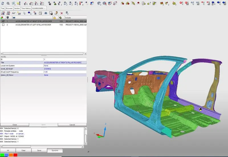
B] "RIGHT B-PILLAR ROCKER"
THE BELOW IMAGE REPRESENTS THE PLACING OF ACCELEROMETER AT "BASE OF RIGHT B-PILLAR ROCKER":
PROCEDURE FOR PLACING A NODE AT GIVEN NODE_ID FOR FINDING OUT "INTRUSION" ON DASH WALLS USING MOVING SKEWS IS AS EXPLAINED BELOW:
IN HYPERMESH:
- GOTO: "Solver" > "Right click" > "Create new" > "TH" > "Nodes" .
- GOTO: "Model" > "Output blocks" > "Right click" > "Create new" > "In ENTITY_ID, select NODES, and select the same node as we selected in the model above or select the same NODE_ID" > "Assign a new skew system by creating a new "SKEW" first in the given model, And select that particular SKEW in this SKEW_ID" > "So now we can get that output when we are ploting the graph".
IN HYPERCRASH:
- GOTO: "Data history" > "Time history" > "Right click and create new" > " Click on TH of nodes" > "In [NODid] Nodes*, select a particular node using the given NODE_ID" > "In [Iskew] Skews (associated to nodes), right click and select 'create new' " > "In TYPE*, select MOVING SKEW".
- Here we have to select "3 NODES" : N1, N2 AND N3.
- Where N1 and N2 DEFINE: X-AXIS.
- The 3rd node N3 DEFINE: Y-AXIS.
- Note that Z-AXIS should always be in parallel with [FN] FORCE or "OPPOSITE" to the direction of the moving component.
- [Iframe] Skew center : "0: center of the local skew".
- Now we should copy all the "NODE ID" of N1, N2 AND N3 to [node_ID1], [node_ID2] and [node_ID3] for representing [FN] and sections.
- Then click on "SAVE".
- There is no need to create a seperate output block as we did in HYPERMESH, since we have directly created in "TIME HISTORY", we get this output directly.
6) WE SHOULD CREATE INTRUSIONS ON DASH WALLS AT GIVEN NODE_ID : "66695" AND "66244" :
- Using the above procedure, we'll obtain the "DISPLACEMENT" of a particular "NODE" with respect to skew after the crash.
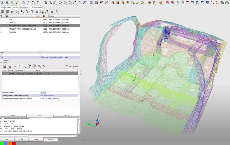
A] "INTRUSION AT "NODE_ID="66695":
THE BELOW IMAGE REPRESENTS THE PLACING OF "NODE_ID="66695" FOR INTRUSION OF THAT PARTICULAR NODE FROM DASH WALL:
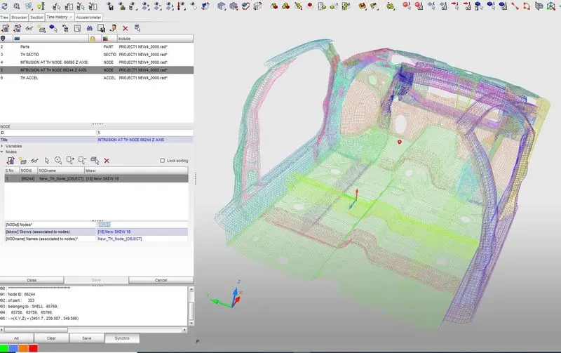
B] "INTRUSION AT "NODE_ID="66244":
THE BELOW IMAGE REPRESENTS THE PLACING OF "NODE_ID="66244" FOR INTRUSION OF THAT PARTICULAR NODE FROM DASH WALL:
NOW WE SHOULD RUN THE SIMULATION :
TO DO THAT
- First import the model from "HYPERCRASH"
- GOTO: "Analysis" > "Radioss" > "Save the RESULTS by directing it from SAVE AS" > "IN option type = -nt 4" > "NOW HIT RADIOSS"
RESULTS, GRAPHS AND CONCLUSIONS:
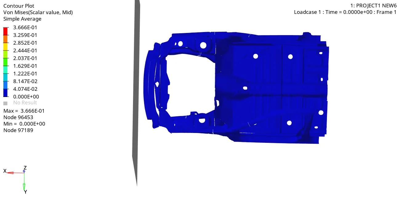
SHOWN BELOW IS THE GIF SIMULATION OF THE FRONTAL CRASH OF THE CAR:
IMAGE:1 :SHOWN BELOW IS THE GIF SIMULATION OF THE FORNTAL CRASH OF THE CAR:
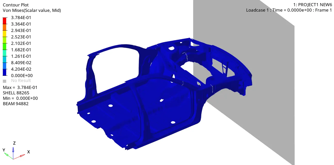
IMAGE:2 :SHOWN BELOW IS THE GIF SIMULATION OF THE FORNTAL CRASH OF THE CAR:
OUTPUT OF SIMULATION:
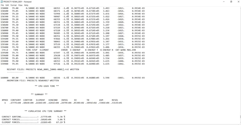
We can see that "ENERGY ERROR" is within the limit., that is "1.5%"
OUTPUT GRAPHS:
1) CROSS-SECTIONAL FORCES IN "RAILS":
A] CROSS SECTIONAL FORCES IN "RAILS" AT LOCATION OF THE INDICATED NODE "174247" AT "LEFT RAIL SECTION" AND THE BELOW IMAGE REPRESENTS "RESULTANT FORCE" THROUGH THAT PARTICULAR SECTION IS AS SHOWN BELOW:
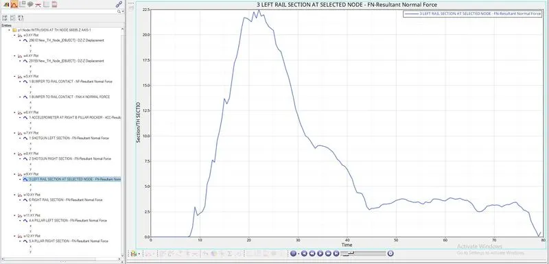
From the above graph the "LEFT RAIL SECTION" at an indicated node receives a maximum Resultant force of 22.5KN through that particular section.
B] CROSS SECTIONAL FORCES IN "RAILS" AT "RIGHT RAIL SECTION" AND THE BELOW IMAGE REPRESENTS "RESULTANT FORCE" THROUGH THAT PARTICULAR SECTION IS AS SHOWN BELOW:
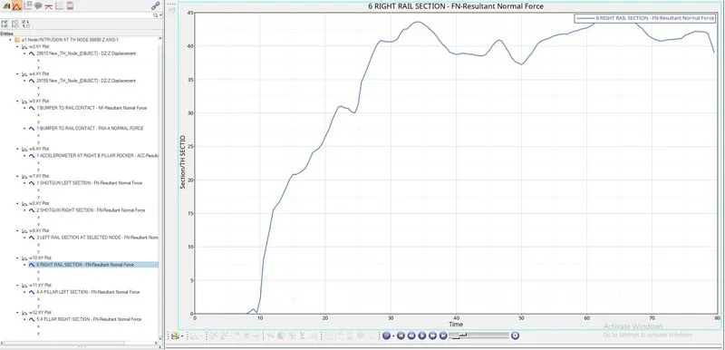
From the above graph the "RIGHT RAIL SECTION" receives a maximum Resultant force of 44KN through that particular section.
2) AXIAL FORCE RECEIVED ON RAILS FROM BUMPER:
BELOW IMAGE SHOWS THE RESULTANT AXIAL FORCE RECEIVED ON RAILS FROM BUMPER:
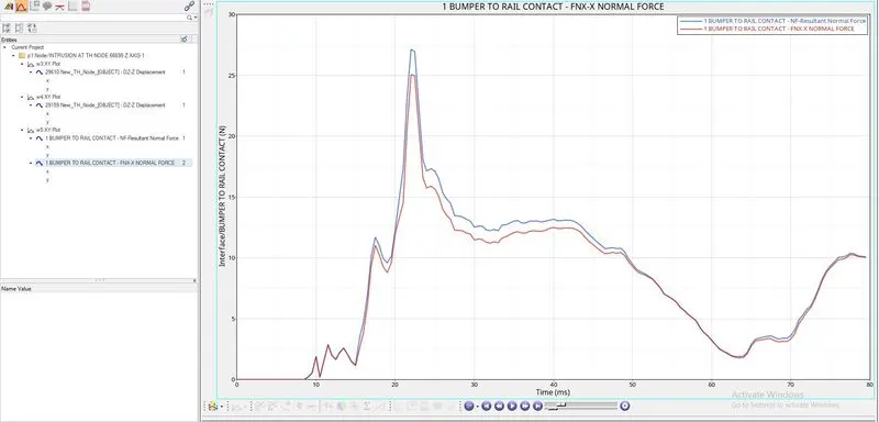
From the above graph the "RAILS" receives a maximum Resultant axial force of 27KN from "BUMPER".
3) CROSS-SECTIONAL FORCES IN "SHOTGUN":
A] CROSS SECTIONAL FORCES IN "SHOTGUN" AT "LEFT SHOTGUN SECTION" AND THE BELOW IMAGE REPRESENTS "RESULTANT FORCE" THROUGH THAT PARTICULAR SECTION IS AS SHOWN BELOW:
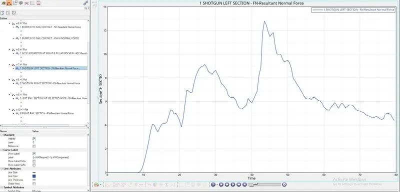
From the above graph the "LEFT SHOTGUN SECTION" receives a maximum Resultant force of 12.99KN through that particular section.
B] CROSS SECTIONAL FORCES IN "SHOTGUN" AT "RIGHT SHOTGUN SECTION" AND THE BELOW IMAGE REPRESENTS "RESULTANT FORCE" THROUGH THAT PARTICULAR SECTION IS AS SHOWN BELOW:
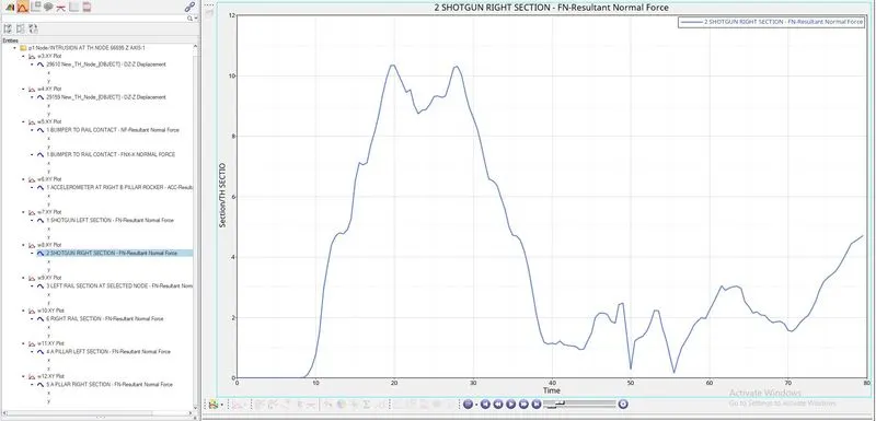
From the above graph the "RIGHT SHOTGUN SECTION" receives a maximum Resultant force of 10.5KN through that particular section.
4) CROSS-SECTIONAL FORCES IN "A-PILLAR":
A] CROSS SECTIONAL FORCES IN "A-PILLAR" AT "LEFT A-PILLAR SECTION" AND THE BELOW IMAGE REPRESENTS "RESULTANT FORCE" THROUGH THAT PARTICULAR SECTION IS AS SHOWN BELOW:
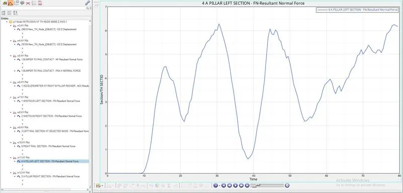
From the above graph the "LEFT A-PILLAR SECTION" receives a maximum Resultant force of 6.25KN through that particular section.
B] CROSS SECTIONAL FORCES IN "A-PILLAR" AT "RIGHT A-PILLAR SECTION" AND THE BELOW IMAGE REPRESENTS "RESULTANT FORCE" THROUGH THAT PARTICULAR SECTION IS AS SHOWN BELOW:
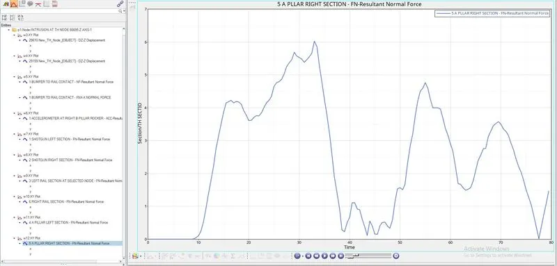
From the above graph the "RIGHT A-PILLAR SECTION" receives a maximum Resultant force of 6.1KN through that particular section.
5) ACCELERATION DETECTED FROM ACCELEROMETER AT "BASE B-PILLAR ROCKER":
A] THE BELOW IMAGE REPRESENTS THE ACCELERATION ON "LEFT BASE B-PILLAR ROCKER" IS AS SHOWN BELOW:
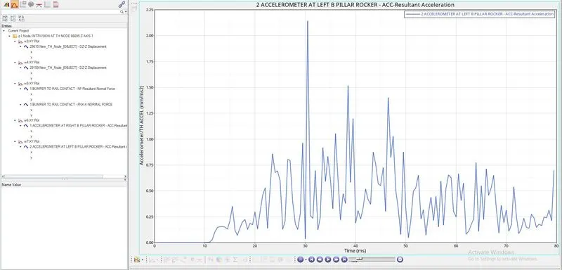
From the above graph the "LEFT BASE B-PILLAR ROCKER" EXPERIENCES A PEAK ACCELERATION OF "2.12mm/ms^2" from that particular indicated node.
B] THE BELOW IMAGE REPRESENTS THE ACCELERATION ON "RIGHT BASE B-PILLAR ROCKER" IS AS SHOWN BELOW:
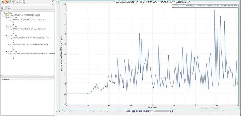
From the above graph the "RIGHT BASE B-PILLAR ROCKER" EXPERIENCES A PEAK ACCELERATION OF "1.68mm/ms^2" from that particular indicated node.
6) INTRUSION FOR THE GIVEN NODES:
A] THE BELOW IMAGE REPRESENTS THE DISPLACEMENT/INTRUSION OF THE NODE "66695" THROUGH LOCAL "Z-AXIS" WHICH IS DEFINED BY A "MOVING SKEW" FROM THE DASH WALL DUE TO THE FRONT CRASH IS AS SHOWN BELOW:
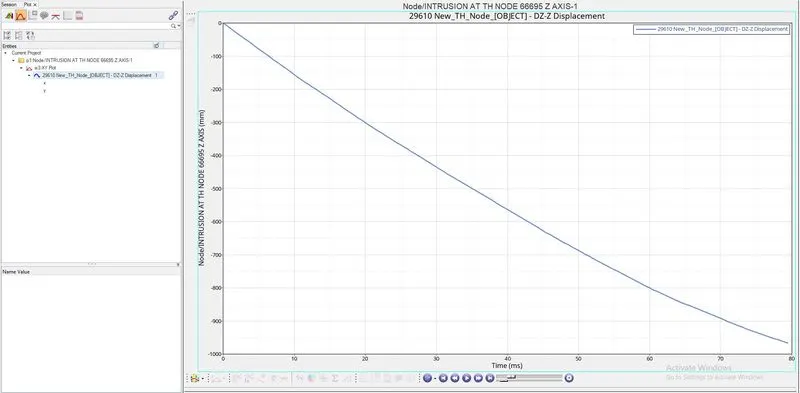
From the above graph we can say that NODE: 66695 has been displaced to 970mm in distance.
B] THE BELOW IMAGE REPRESENTS THE DISPLACEMENT/INTRUSION OF THE NODE "66244" THROUGH LOCAL "Z-AXIS" WHICH IS DEFINED BY A "MOVING SKEW" FROM THE DASH WALL DUE TO THE FRONT CRASH IS AS SHOWN BELOW:
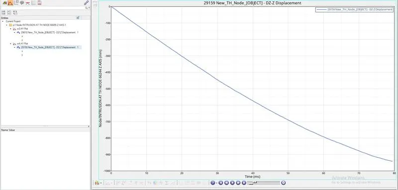
From the above graph we can say that NODE: 66695 has been displaced to 940mm in distance.
7) ENERGY PLOTS:
THIS INCLUDES:
- INTERNAL ENERGY
- KINETIC ENERGY
- HOURGLASS ENERGY
- CONTACT ENERGY
- TOTAL RESULTANT ENERGY
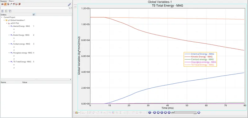
INTERNAL ENERGY:
- In the above graph "INTERNAL ENERGY" is constant and is "0" for "8.5 seconds", this is because the car is still moving towards the "RIGID POLE" and has not yet crushed, so there will be no "ENERGY ABSORPTION" untill and unless the car is being CRASHED to the RIGID POLE
- We can see that "INTERNAL ENERGY" increases as the car is getting crushed, which means the car is absorbing the energy induced by the molecular movements in the component, this is because of crushing of the elements in the components.
KINETIC ENERGY:
- Initially the "KINETIC ENERGY" is "HIGH" and "CONSTANT" for "8.5 seconds", that is because the car is moving without facing any obsticle or it has not reached the "RIGID WALL" yet, as soon as the car hits the RIGID WALL, the "KINETIC ENERGY" of the car keeps on decreasing, but from the above graph we can see that the "KINETIC ENERGY" is still high at the end of cycle, this tells that the car still did'nt come to rest.
HOURGLASS ENERGY:
- Since we are using "QEPH" as our shell element, which is also a "IMPROVED UNDER INTEGRATED ELEMENT" which has "PHYSICAL HOURGLASS STABILIZATION", so from the above graph we can say that "HOURGLASS ENERGY" experienced by the car is very less.
CONTACT ENERGY:
- Since we have defined the contact interfaces between the car and the impactor by "TYPE-7" with "FRICTION" = 0.2, from the above graph we can see that there is a slight "CONTACT ENERGY" experienced at "CONTACT" between the two.
TOTAL RESULTANT ENERGY:
- From the above graph we can see that "TOTAL RESULTANT ENERGY" is decreasing very slightly, this is due to the slight increase in the "CONTACT ENERGY". so, "TOTAL RESULTANT ENERGY" depends on "CONTACT ENERGY", Since it is the SUM of all the energies that are listed above the graph.
CONCLUSION:
Hence the "FRONTAL CRASH" simulation is done for the given model by using the given appropriate parameters and the respective results are analysed and plotted.