Assignment 5-RADIOSS Interfaces & Study of Effect of Notches Challenge
AIM:
To create mesh for bumper assemblu and runthe crash tube model as per the given conditions and plot the graphs required as mentioned in the question.
Objective:
Create the mesh for bumper assembly,mesh size should be 6mm.
- Run the crash tube model as it is.
- Change the Inacti=6 and run.
- Create the type 11 contact and run.
- Remove both notches and remove boundary condition on rigid body node then run.
- Create a new notch in the middle ,select the whole section and run.
- Create a new notch with nodes only from opposing 2 faces and run.
Theory:
1. Contact Interface Modeling:
The explicit analysis meathod efficiently solves complex dynamic problems. Accurate modeling of contact interfaces is essential to correctly capture contact interaction between bodies.
2. Penality Meathos:
Interfaces using the pemalty meathod are based on master or slave treatment. contact can only occur between a set of smaster and slave segnments.
3.Interface Type-7:
Automatic node to surface contact interface using penality meathod with variable stifness. A gap is defined around the master segment and the slave node. The contact gap be constant or variable.
4.Interface Type-11: Edge to Edge Contact:
This interface simulates impact between edge to edge lines. Aline can be a beam or truss element or a shell edge or spring elements. In association with interface type7, interface type11 solves the locking cases.
Procedure:
Study-1: Bumper Assembly
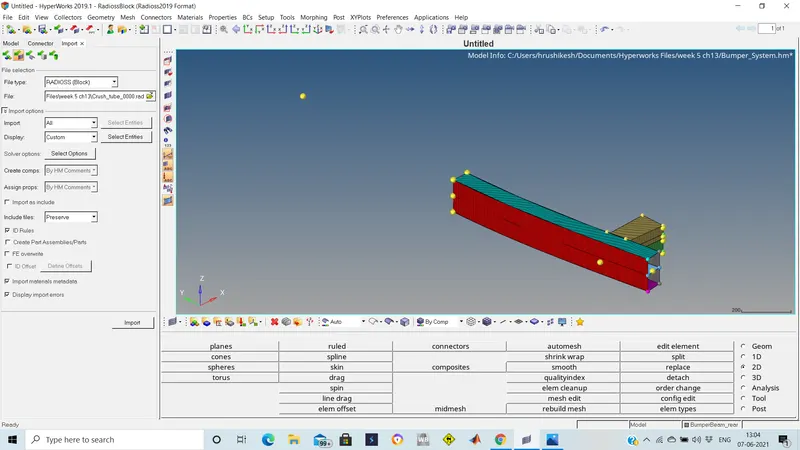
1.Open the bumper assembly model using file--open--model.
2.Clearing unwanted nodes.
3.Check for errors in geometry and connections in model.
4.Clear the errors using togglie command.
5.After clearning the errors then using 2D meshing command and element size 6mm mesh the model.
7.Remove all the tria elements.
8. Mesh all the components and joining components with same element size.
STUDY 2: CRASH BODY
Case1:
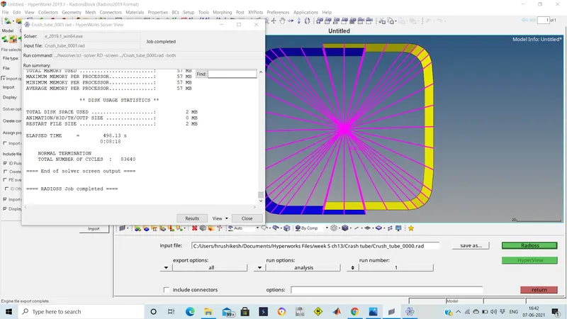
1.Import the crash tube model in the hypermesh.The Input file wit 0000.rad to be impoeted.
2.After The model run the simulation using the radioss solver.
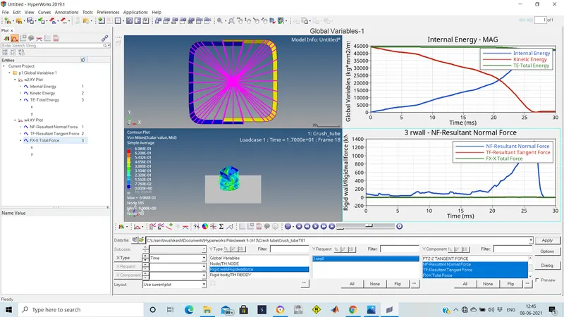
3. Create TH by usinh the solver---TH and create it.
4.Change the hypermesh to hyperview and import the h3d folder and apply it.
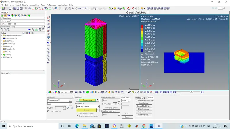
5.Select the countour and apply the Vonmisses, Dispalcement and click apply.
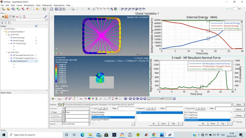
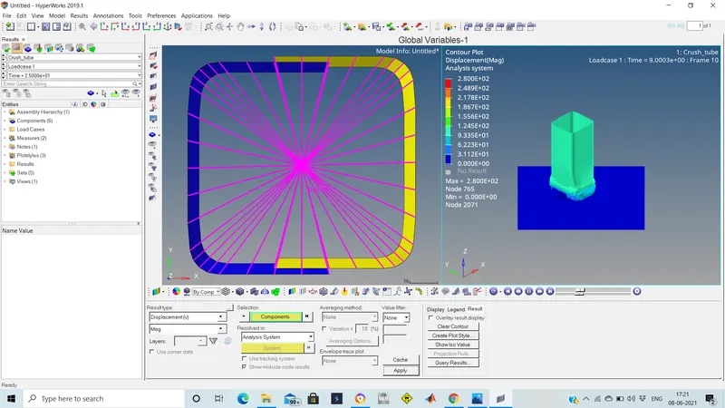
Case 2:
1.Import the crash tube model of case 1 in the hypermesh.The Input file wit 0000.rad to be impoeted.
2.After The model is imported change the inacti to 6 and run the simulation using the radioss solver.
3. Create TH by usinh the solver---TH and create it.
4.Change the hypermesh to hyperview and import the h3d folder and apply it.
5.Select the countour and apply the Vonmisses, Dispalcement and click apply.
Case 3:
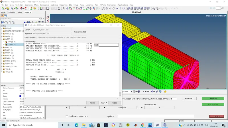
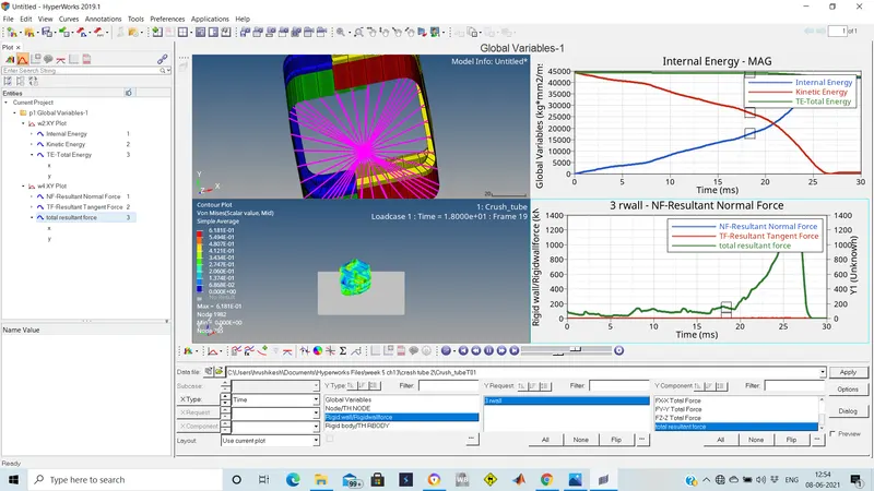
1.Import the crash tube model of case 2 in the hypermesh.The Input file wit 0000.rad to be impoeted.
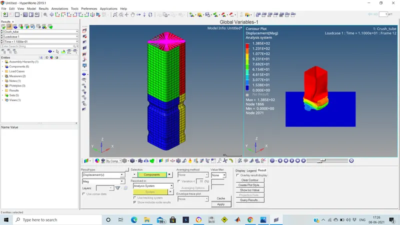
2.After The model is imported create type 11 and make the entries in the properties of the card and run the simulation using the radioss solver.
3. Create TH by usinh the solver---TH and create it.
4.Change the hypermesh to hyperview and import the h3d folder and apply it.
5.Select the countour and apply the Vonmisses, Dispalcement and click apply.
Case 4:
1.Import the crash tube model of case 3 in the hypermesh.The Input file wit 0000.rad to be impoeted.
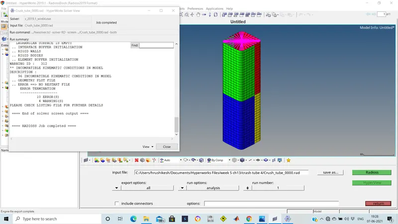
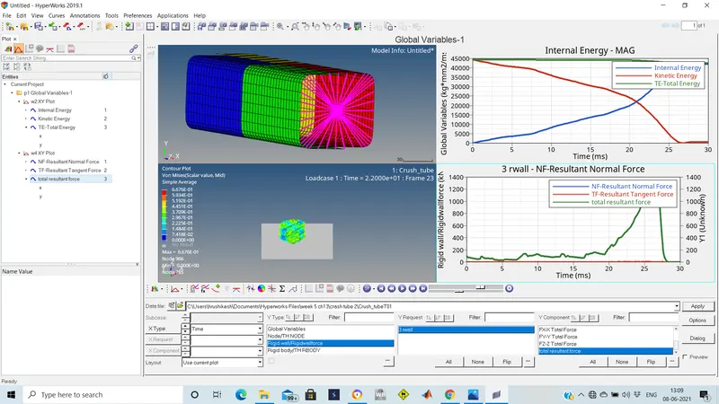
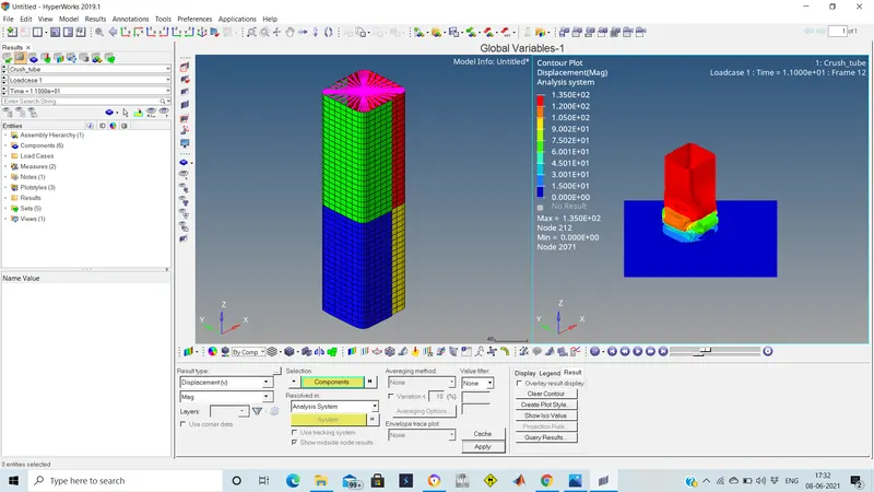
2.After The model is imported the notches are removes usinh the goemetry--node edit--align. The nodes are alligned and the boundary conditions aare removed and run the simulation using the radioss solver.
3. Create TH by usinh the solver---TH and create it.
4.Change the hypermesh to hyperview and import the h3d folder and apply it.
5.Select the countour and apply the Vonmisses, Dispalcement and click apply.
Case 5:
1.Import the crash tube model of case 4 in the hypermesh.The Input file wit 0000.rad to be impoeted.
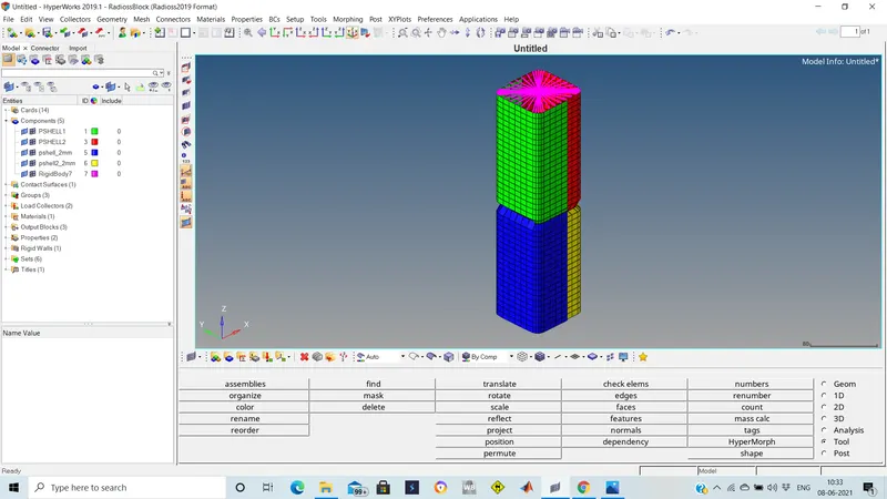
2.After The model is imported and then using tool---translate the notch is created at the middle of the model of the 4 components and then run the simulation using the radioss solver.
3. Create TH by usinh the solver---TH and create it.
4.Change the hypermesh to hyperview and import the h3d folder and apply it.
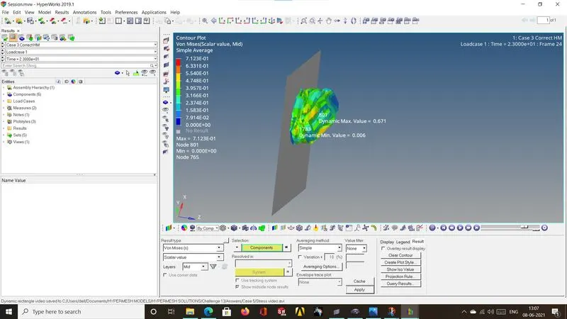
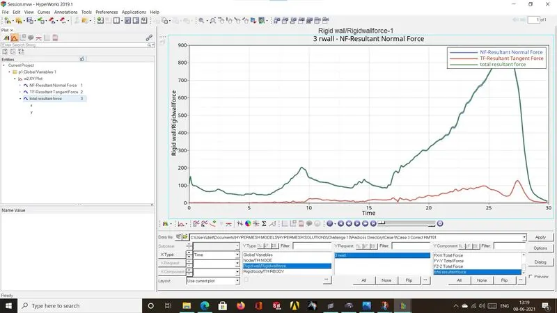
5.Select the countour and apply the Vonmisses, Dispalcement and click apply.
Case 6:
1.Import the crash tube model of case 5 in the hypermesh.The Input file wit 0000.rad to be impoeted.
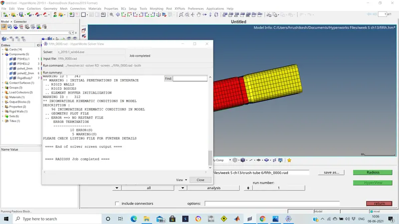
2.After The model is imported and then using tool---translate the new notch is created at the opposing 2 faces of the model of the 4 components and then run the simulation using the radioss solver.
3. Create TH by usinh the solver---TH and create it.
4.Change the hypermesh to hyperview and import the h3d folder and apply it.
5.Select the countour and apply the Vonmisses, Dispalcement and click apply.
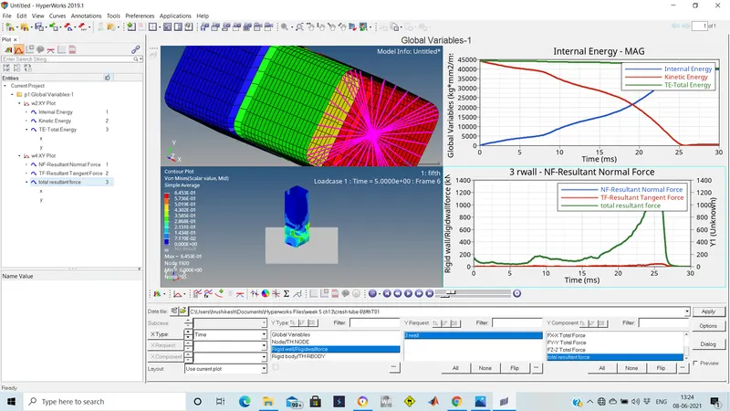
Results:
case1: max stress=6.98e-01, disp=2.82E02mm, max K.E=45000j
case2: max stress=6.98e-01, disp=2.80E02mm, max K.E=45000j
case3: max stress=6.18e-01, disp=1.38E02mm, max K.E=44500j
case4: max stress=6.67e-01, disp=1.35E02mm, max K.E=45000j
case5: max stress=7.12e-01, disp=2.91E02mm, max K.E=45000j
case6: max stress=6.45e-01, disp=1.98E02mm, max K.E=44500j
Conclusions:
The displacement increases with the prescence of notches.
The stresses induced get increased with prescecnse of notches.
The mesh is created to the bumper assembly.