Assignment 5-RADIOSS Interfaces & Study of Effect of Notches Challenge
AIM: To perform crash and analyze the results on each modification
this is done in two process as given,
- compare the contact parameters between the type 7 and type 11
- notch modifications in the model
PROCEDURE:
all these operations are carried out in a case wise ,
- Create the mesh for bumper assembly,mesh size should be 6mm.
- Run the crash tube model as it is.
- Change the Inacti=6 and run.
- Create the type 11 contact and run.
- Remove both notches and remove boundary condition on rigid body node then run.
- Create a new notch in the middle ,select the whole section and run.
- Create a new notch with nodes only from opposing 2 faces and run.
CASE1:Run the crash tube model as it is.
- import the model, as it is in .rad file , use the solver import command
- chck for the irreguralties , like free edgs and elements normals, as normals play an important role in contacts
- Go to ANALYSIS>>RADIOSS>SAVEFILE. by including all the connections
- set the preference as "-nt 4" and run tthe simulation
- if all the buildup is accurate, then simulation will be successful,go to hyperview and compare the results
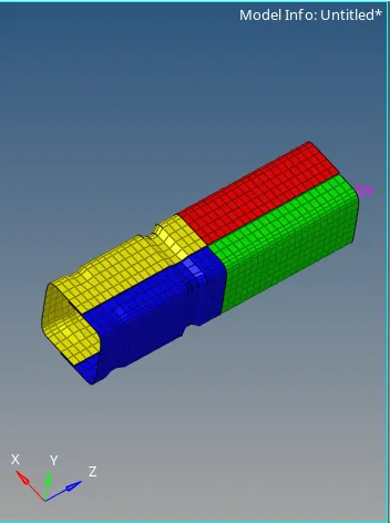
- run the simulation
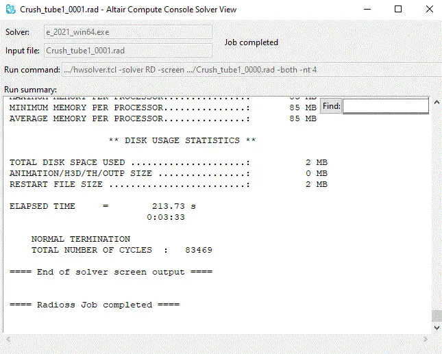
- click on results and view in hyperview pannel
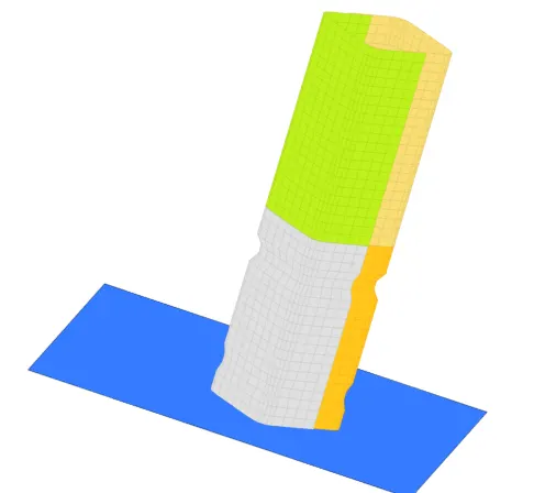
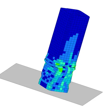
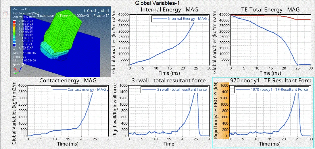
- results of the analysis are extracted and compared in hte hyper graph as shown
CASE2: Change the Inacti=6 and run.
- Simillarly as in the above case,import the model
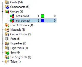
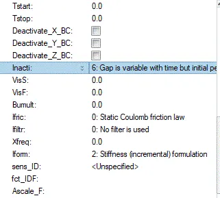
- now, we have to set the contact parameter i.e, Iacti=6 from the model tree
- Go to model browser>>GROUPS>SEAM2(TYPE7CONTACT)>>INACTI=6
- also change the name as, type7 as we are to be comparing both the type7 and anf type11 contacts in future cases
- update the model save the destinatin as case2 and run the radioss, if all the parameters are setin correctly simulation will run sucessfully
- extract the results and compare them
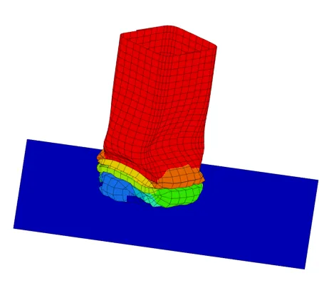
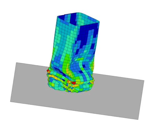
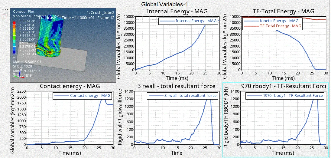
- simillarly also, plot all the contact forces,internal energies,contact energy for this case, these are as shown
CASE3:Create the type 11 contact and run.
- Now, we are changing the contact type to type 11
- VIEW>>BOWSER>>HYPERMESH>>SLOVER
- from the solver card open the INTER card>> dropdown and create a new contact card ad TYPE11
- keep all the parameters i side the type 11 as , type 7 recomamended
- here, type type 11 is a edge toedge contact but, most of the parameters resemble to type which is a node to surface contact
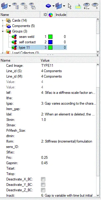
- ANALYSIS>>RADIOSS>>SAVE FILE>> INCLUDE CONNECTIONS>>"-nt 4"
- run the simulation,and extract the results
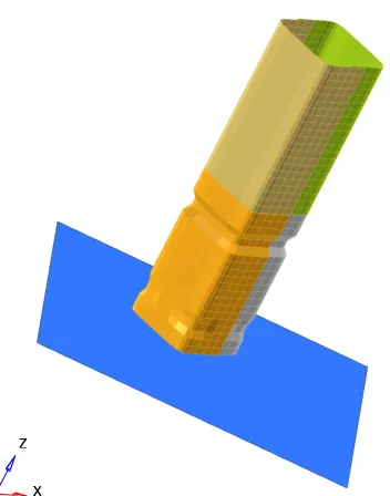
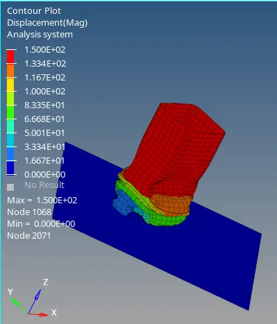
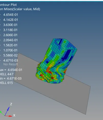
- graphs are plotted for this ccase , which are as shown
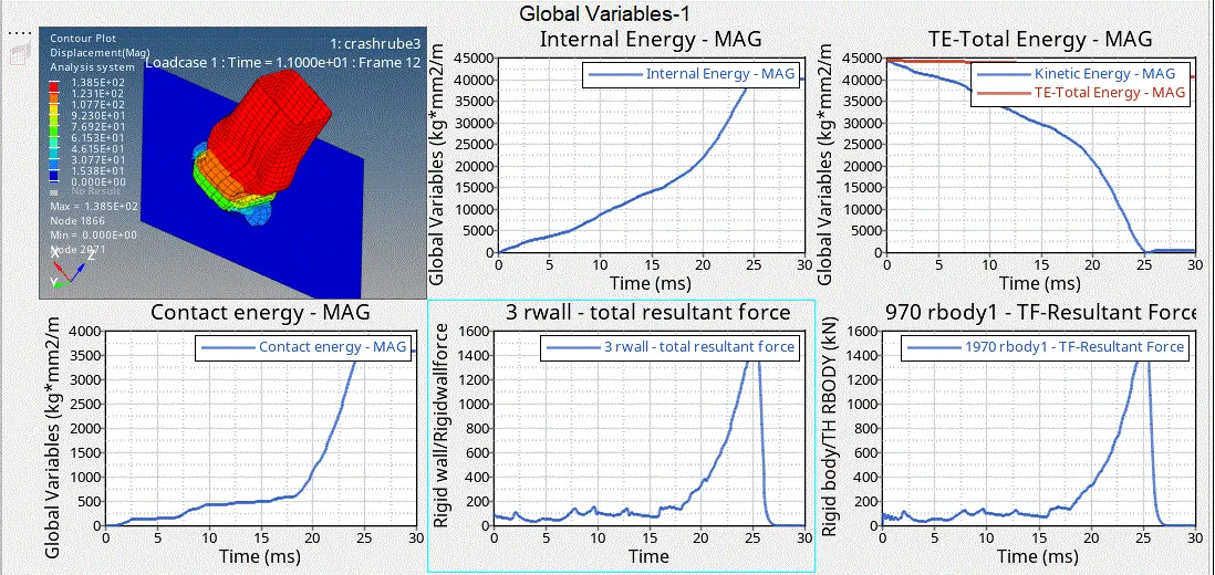
Till nowwe have been comoaring te results between the contact type , now in the following 3 case we compare with the effect of notches
CASE4:Remove both notches and remove boundary condition on rigid body node then run.
- import the model on to the work scape
- now, delete the boundary conditions card
- VIEW>>BROWSER>>HYPERMESH>>SOLVER>> BSC card
- delete the card and now alter the mesh with the given requirement
- we have to change the node location i.e, we have to remove the notches present in the FE
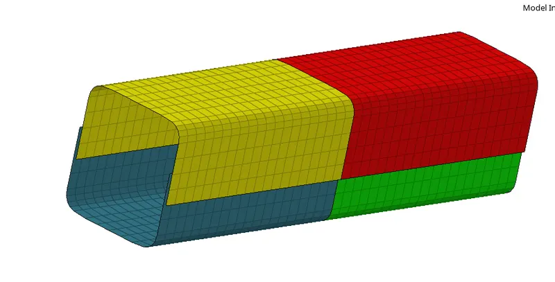
- as you can see all the notches in the meshare removed
- this could be done in 2 wys
- translate
- node alignment
- as node alignment is a single function commnad it can't be used, so we can use both these commands to cleaf the notches
- once the notches are cleare then, set the model for simulation
- simillarly extract the results and plot the graphs
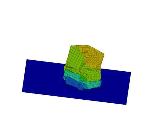
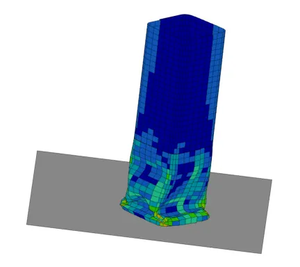
- as we could denetly see the hange of deformnation, displacement,and stress concentration in the mesh due to the absence of themesh
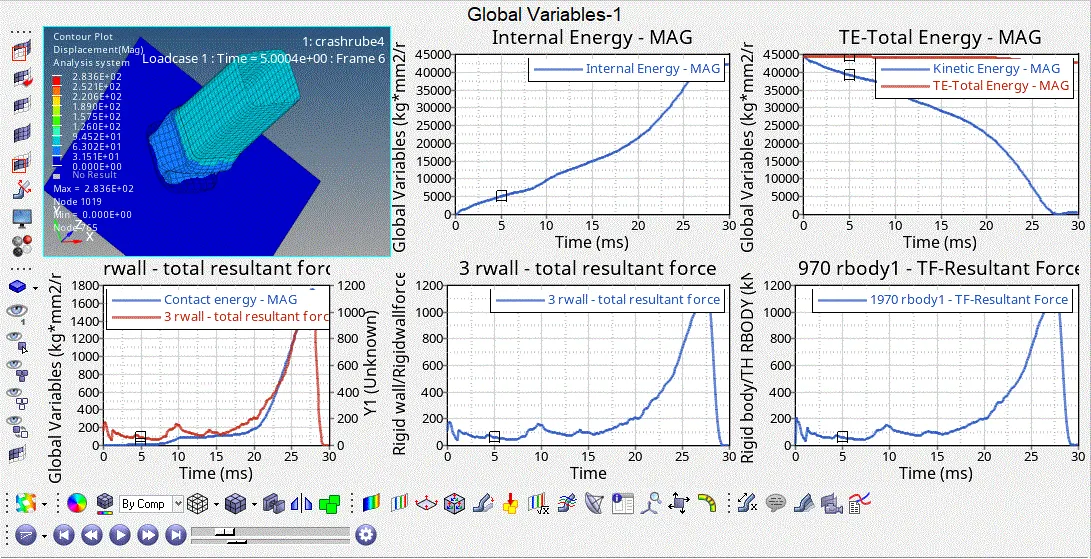
- all the neceaasry graphs are ploted against the time step and as shown
CASE5:Create a new notch in the middle ,select the whole section and run.
- IN THIS case we have to locatio of the notch from the initial model
- import the previous model and change the mnode locations'
- thos could be done in the above discussed methodes
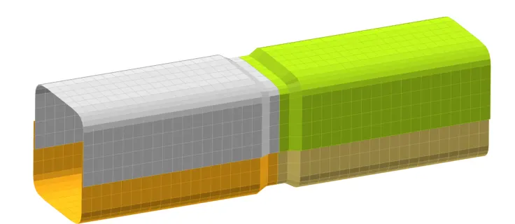
- as you see , we have created a notch in the middle of the model
- check of the free edges, normals in the model as we have changes the location of the node
- simillar to the above cases, set in the simulate
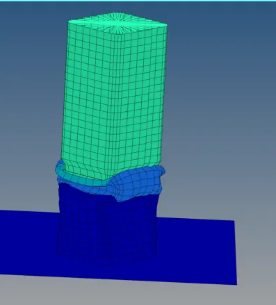
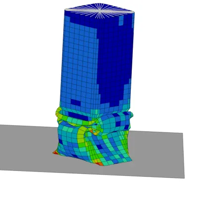
- observe the change in the deformation
- it occurs early compared to the previous cases,even the deformation also changes , happen at the notch little a head compared to the above cases
CASE6:reate a new notch with nodes only from opposing 2 faces and run.
- Here in this case , notches are to be present only at the opposite sides
- notches are to be only present on 2 sides of the fe model
- observe where ere the notches present in the mesh
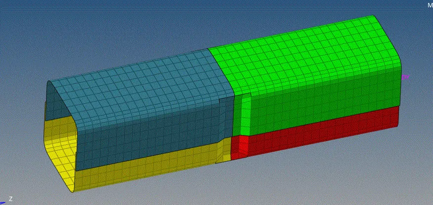
- as you can see the notches are at the side mating area of the mesh
- chack and simulate the model
- results are as shown in the figure
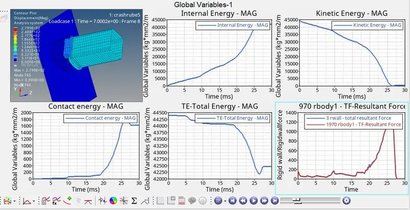
COMPARISON OF RESULTS:
here we ae coparing in two sets as given
- contact type: case1,2,3
- notch bases: case 4,5.6
COMPARISION OF CASE 1 WITH RESPECT TO 2,3:
lets compare case1 with case 2,3 because it base simulation with out any changes
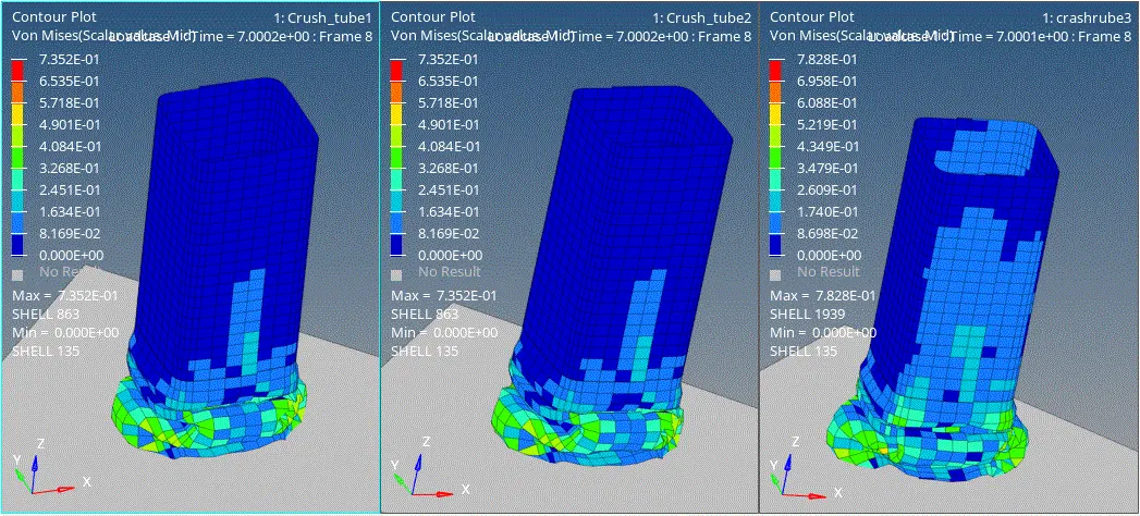
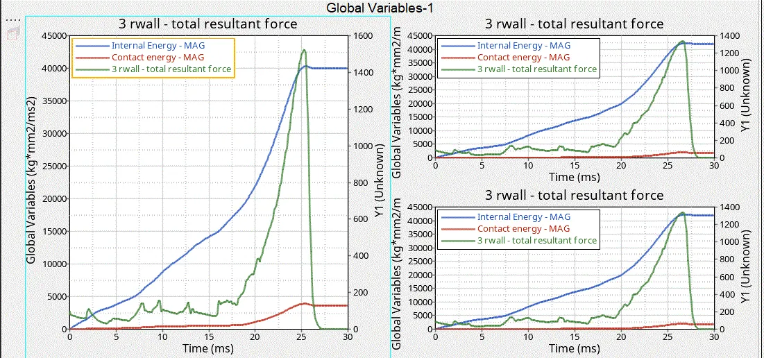
graph comparision between, contact ,internal , rigidwall forces
CASE1:
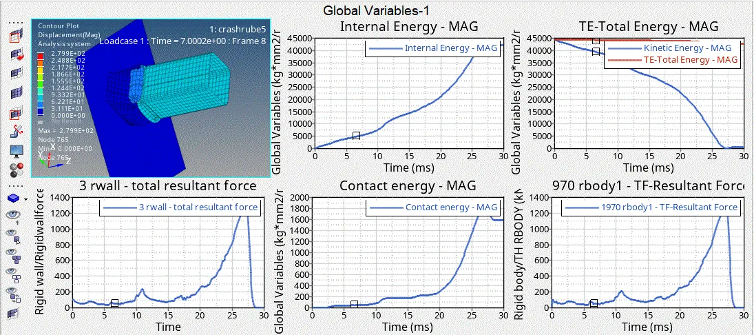
- here, internal energy peaks at a point of time at, T=28 ms obtainng 42500J and decreases due to contact resistance between the node s and the surfaces
- also, contact energy will be maxium at the same time 2000J and then decreaes due to repulsions
- vonmisses=7.35e-1, displacemet= 2.8e+2, contct force= 9.35e+1
CASE2:
- here we just chsnged Iacti value to 6, which is bacisally a default value as in case 1, it is '0', but the hypermesh reads it as 6
- here by given iacti=6, similar results will occur as case1
- internal energy=42500J,contact energy= 2000J, at time poinnt t=28ms
- even the stress, displacement,and cintact forces will be as as csse 1
- vonmisses=7.35e-1, displacemet= 2.8e+2, contct force= 9.35e+1 simillar to case1
CASE3:
- here , we can clearly see the difference, we have chnge the contact tyoe as type 11, with type7 parameters
- type11 is edge to dge contact, so the repulsion occur a bit earlier to the above cases at T=25 ms
- contact , irigidwall forces also increase at that time point and the decreses due to resistance
- internal energy=40000J,contact energy=3800J, at time poinnt t=25ms
2.COMPARISON AMONG CASE4,5,6:
all these three case are of type 7 as similar to to the case1 in terms of contact, the only difference is in the location of the notches on the model mesh
case4:
- in this case we have removed the notches entirely as seen above
- as a result the extracted simulated values are as fallowes
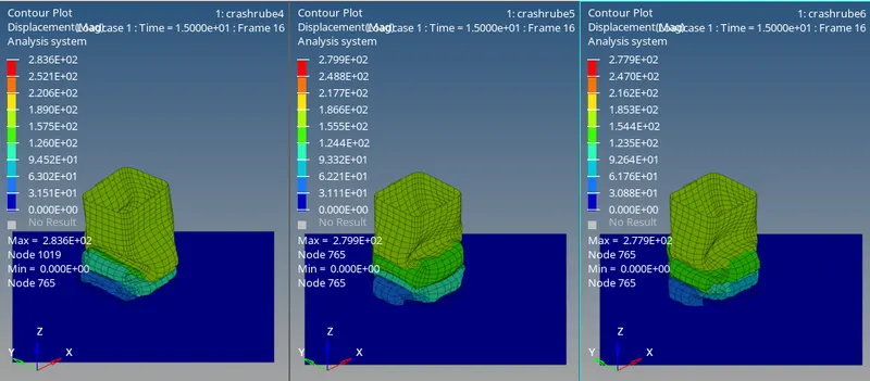
- grapg comparison of, contact energy, internal energy,wallforces of cae4,5,6
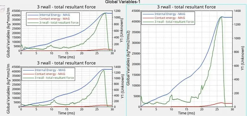
case4:
- all the values occur at same range to case1
- internal energy=42500J,contact energy= 1750J,wall forces=1100J at time poinnt t=27ms
- here no contact type is changed, so occurs at time T=27 ms, same as case1 and after that the resistance build in between the nodes and surfaces
- as, the notches are considerabilly changed location, conact energy values increase hare at maxium it is 1750J
case5:
- hare notch is at the middle , due to these the contact energy is increased
- even the behaviour of deformation also changes , it first starts at the middle notch reagion
- internal energy=42400J,contact energy= 1850J,wall forces=1250J at time poinnt t=27ms
- here no contact type is changed, so occurs at time T=27 ms, same as case1 and after that the resistance build in between the nodes and surfaces
caase6:
- here, notches are present only at 2 sides
- all the values of, contact force, contact energy,wall forces considerablly increases
- internal energy=42400J,contact energy= 1950J,wall forces=1300J at time poinnt t=27ms
- here no contact type is changed, so occurs at time T=27 ms, same as case1 and after that the resistance build in between the nodes and surfaces
all the above results are tabulated so as to get a clear stastaical view of the results
- also presence of notches mostly increases the strain rate, i.e, more strain suatains more amout of forces during the simulation
| CASE | WALLFORCES(N) | CONTACT ENERGY(J) | INTERNAL ENERGY(J) | VONMISSES | DISPLACEMENT | CONTACT FORCE(N) | simulation time | cycles |
| 1 | 1300 | 2000 | 42500 | 7.35e-1 | 2.800e+2 | 9.38e+1 | 201 | 83469 |
| 2 | 1300 | 2000 | 42500 | 7.35e-1 | 2.800e+2 | 9.38e+1 | 201 | 83469 |
| 3 | 1500 | 3900 | 40500 | 7.825e-1 | 2.650e+2 | 5.72e+2 | 568 | 111003 |
| 4 | 1100 | 1750 | 42200 | 7.42e-1 | 2.836e+2 | 6.074e+1 | 210 | 73288 |
| 5 | 1250 | 1800 | 42200 | 7.64e-1 | 2.789e+2 | 2.098e+2 | 265 | 106508 |
| 6 | 1300 | 1900 | 42200 | 7.22e-1 | 2.773e+2 | 8.288e+1 | 258 | 95211 |