Assignment 5-RADIOSS Interfaces & Study of Effect of Notches Challenge
Aim : To create the mesh for given bumper assembly with element size of 6mm and to perform simulations for crash tube and to study the RADIOSS interfaces and the effect of notches using Hypermesh, Hypergraph 2D, Hyperview.
Objectives :
- To create mesh for bumper assembly with mesh size of 6mm.
- To apply the recommended properties and study of crash tube simulations.
- To study the effect of notches on crash tube.
- To plot the RWALL forces, contact forces, internal energy.
- To compare the results of all the different simulations by their no of cycles, energy error, time elapsed and maximum von misses stresses.
Procedure :
Objective 1 : To create 2D mesh with element size 6mm.
- The given geometry has to be imported and clean up geometry.
- Surface extension and trim for surface to surface can be done for cleaning geometry for this model.
- For importing FILE>IMPORT>MODEL>BROWSE .
- Clear temporary nodes by going to Geometry>temp nodes>clear all.

- For cleaning up go to geometry>surface edit>extend>slect surfaces to extend.
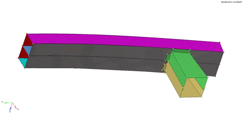
- Perform meshing with elemnt size of 6mm and select surfaces.
- For meshing go to 2D>Automesh>and select surfaces to be meshed.

Images :
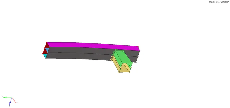
Before meshing :
After meshing :
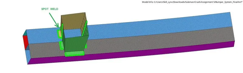
Result :
Objective 2 : To apply the recommended properties and study of crash tube simulations.
As per the given question there are 6 cases where properties have to be changed and run the simulations.
Case 1 : Simulating and analysing crush tube model as it is given in challenge.
Step 1 : Open Hyperworks in Radioss solver.
Step 2 : Import Solver desk Crash_Tube_0000.rad file
Step 3 : Simulating model as it is.
Analysis>Radioss>save as input Case_1_Crash_Tube_0000.rad file>Checkbox include collectors>Write (-nt 4) in options>Click Radioss
Step 4 : Switch to Hyper view
Step 5 : Select local model and result Case_1_Crash_Tube.h3d file
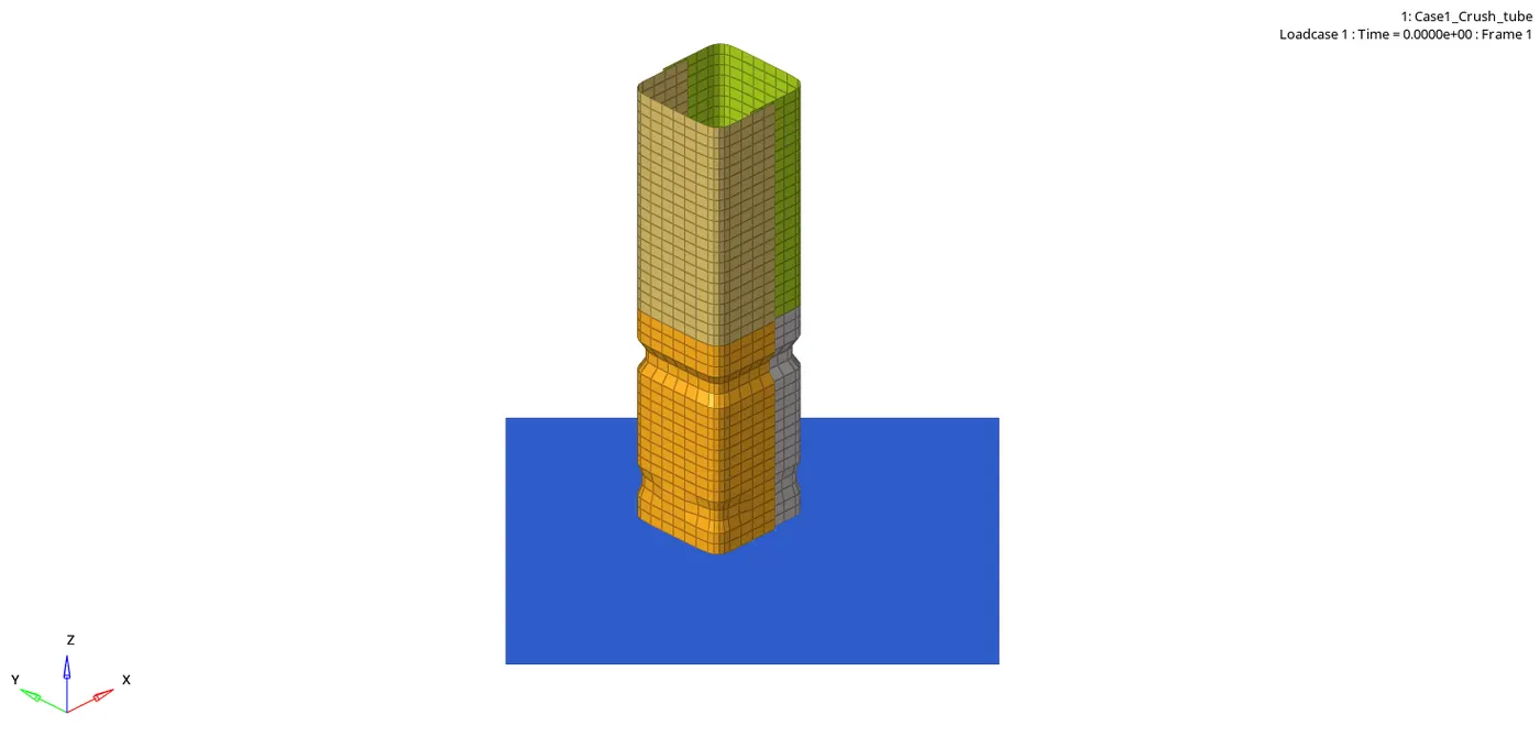
- Von-mises contour
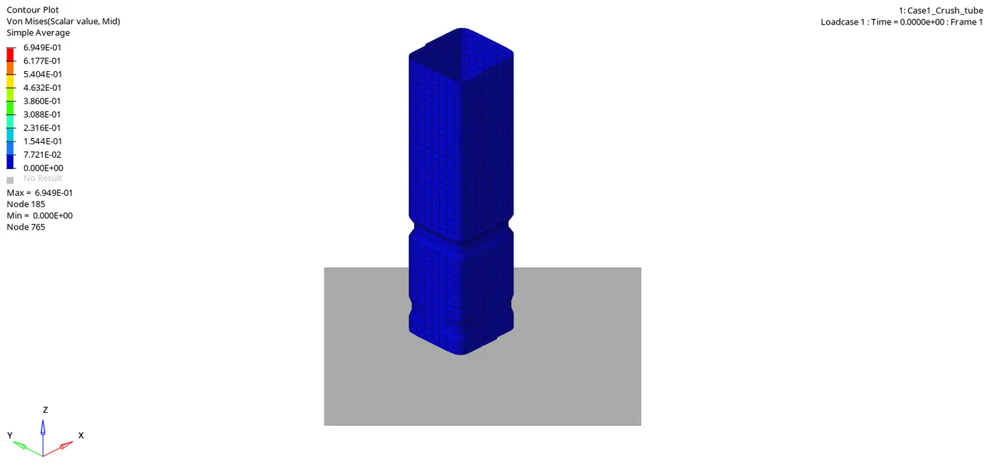
Step 6 : Checking the number of cycles it takes, energy error, mass error and simulation time.
- Number of cycles = 83496
- Energy error = -3.8%
- Mass error = 0.0
- Simulation time = Starter+Engine run time = 140.16 s
Step 7 : Observing Kinetic,Internal,Contact and Total energy. Switch to Hypergraph 2D, upload Case_1_Crash_TubeT01
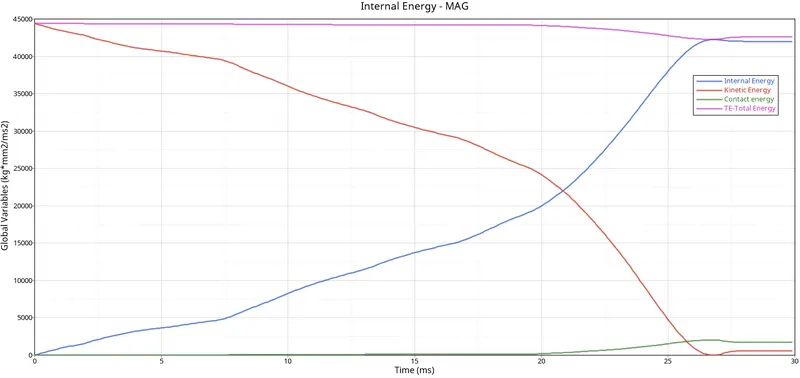
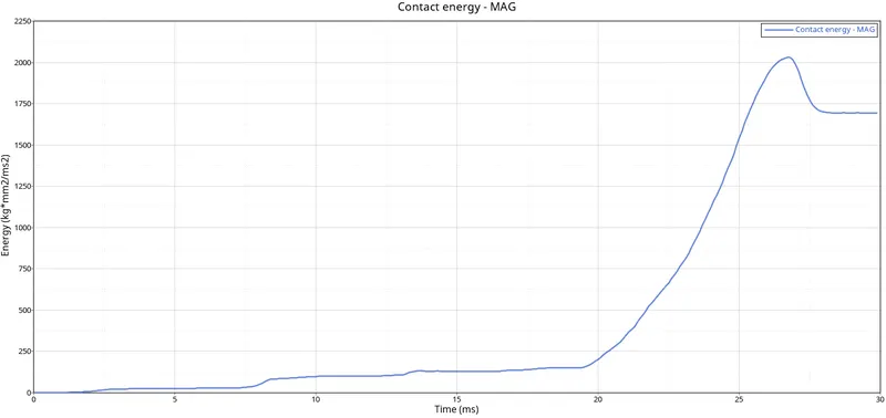
Step 8 : Observing Rigid Wall Forces
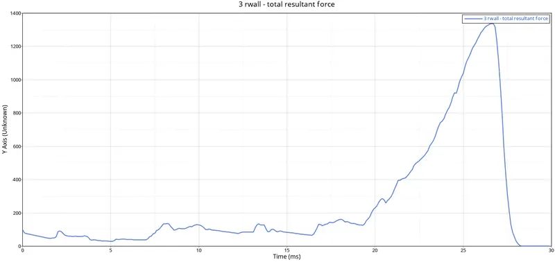
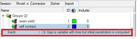
Case 2 : Simulating and analysing crush tube model after Changing Inacti = 6 in group’s self contact collector.
Step 1 : Open Hyperworks in Radioss solver. Import Solver desk Case_2_Crush_Tube_0000.rad file
Step 2 : Changing Inacti = 6 in group’s self contact collector.
Step 3 : Simulating model
Analysis>Radioss>save as input Case_2_Crush_Tube_0000.rad file>Checkbox include collectors>Write (-nt 4) in options>Click Radioss
Step 4 : Switch to Hyper view
Step 5 : Select local model and result Case_2_Crush_Tube.h3d file
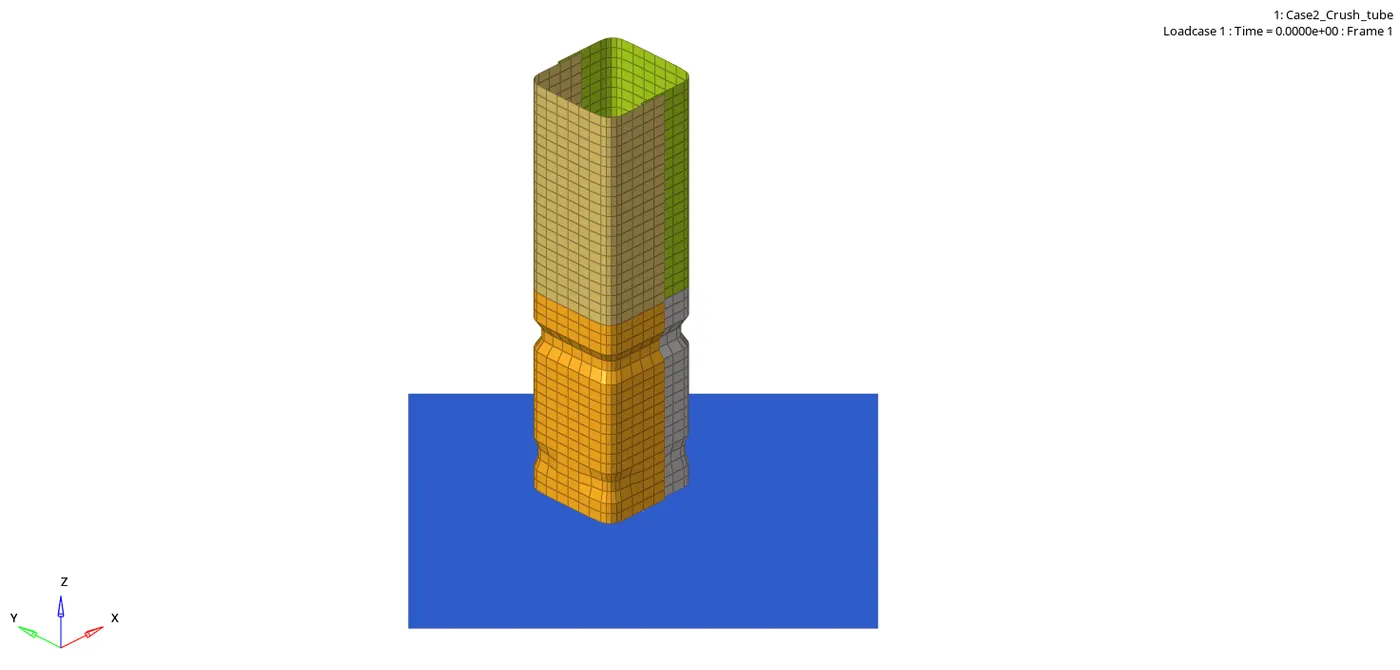
- Von-mises contour
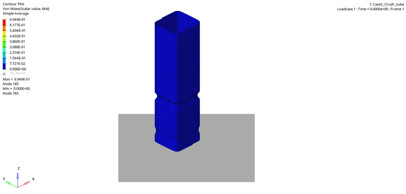
Step 6 : Checking the number of cycles it takes, energy error, mass error and simulation time.
- Number of cycles = 83496
- Energy error = -3.8%
- Mass error = 0.0
- Simulation time = Starter+Engine run time = 139.47 s
Step 7 : Observing Kinetic,Internal,Contact and Total energy. Switch to Hypergraph 2D, upload Case_2_Crush_TubeT01
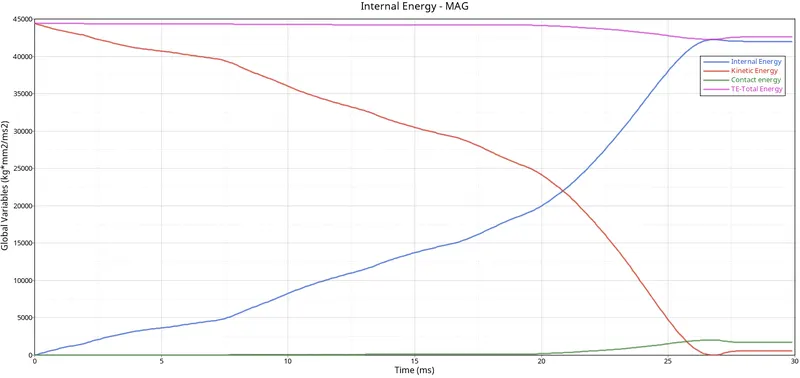
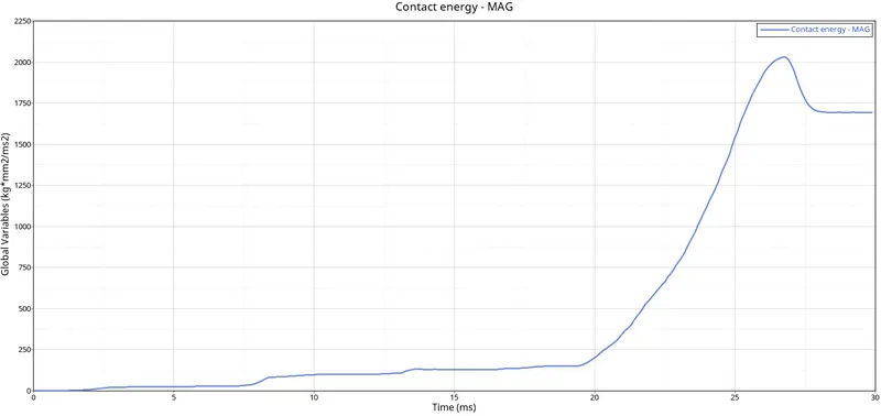
Step 8 : Observing Rigid Wall Forces
Case 3 : Simulating and analysing crush tube model after Creating Type 11 Parameters.
Step 1 : Open Hyperworks in Radioss solver. Import Solver desk Case_2_Crush_Tube_0000.rad file
Step 2 : Creating Type 11 Parameters
CREATE>INTER>TYPE 11> and set the values of card as shown in below images.
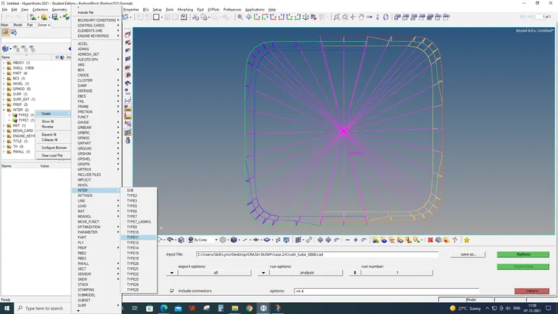
Values for interface card :
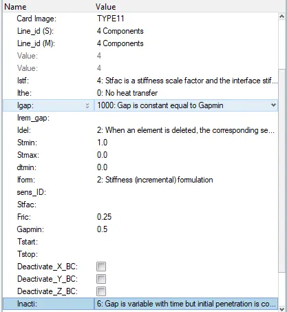
Step 3 : Simulating model
Analysis>Radioss>save as input Case_3_Crush_Tube_0000.rad file>Checkbox include collectors>Write (-nt 4) in options>Click Radioss
Step 4 : Switch to Hyper view
Step 5 : Select local model and result Case_3_Crush_Tube.h3d file
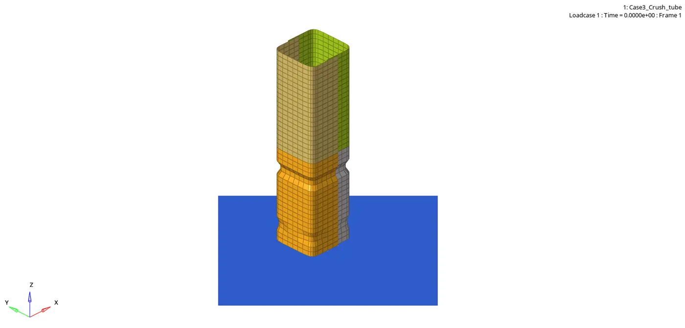
- Von-mises contour
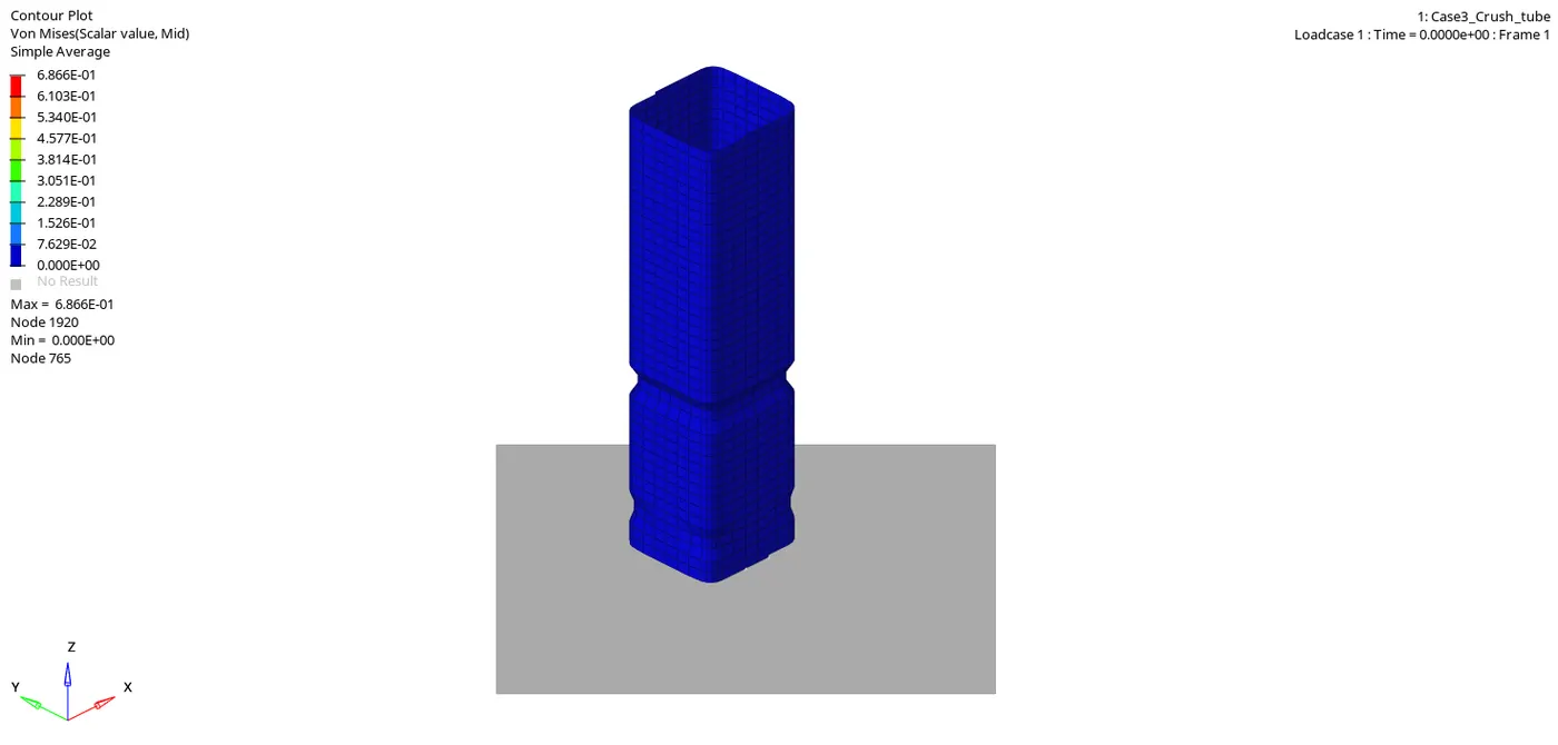
STEP 6 : Checking the number of cycles it takes, energy error, mass error and simulation time.
- Number of cycles = 413904
- Energy error = -3.1%
- Mass error = 0.0
- Simulation time = Starter+Engine run time = 706.74 s
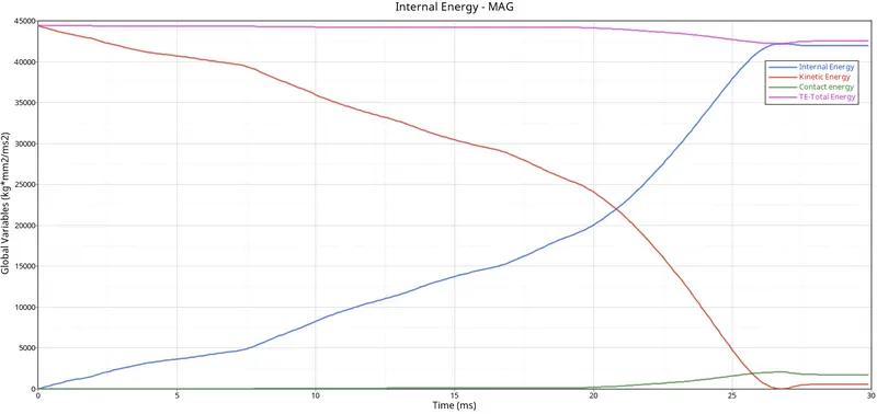
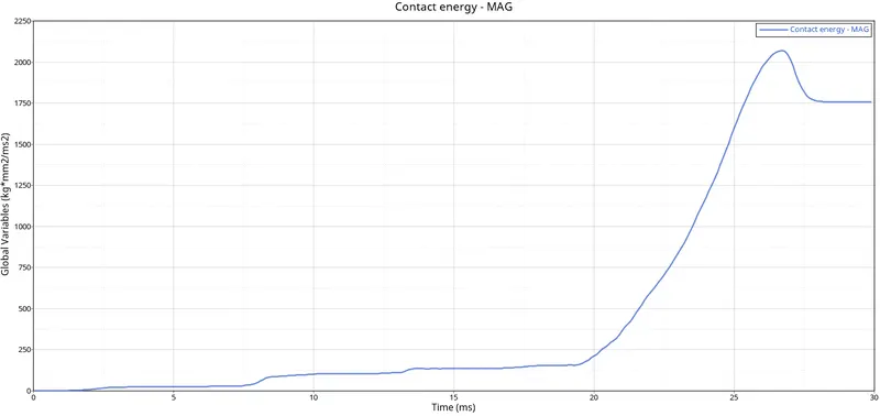
Step 7 : Observing Kinetic,Internal,Contact and Total energy. Switch to Hypergraph 2D, upload Case_3_Crush_TubeT01
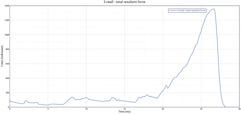
Step 8 : Observing Rigid Wall Forces
Case 4 : Simulating and analysing crush tube model after removing both notches and deleting boundary condition.
Step 1 : Open Hyperworks in Radioss solver. Import Solver desk Case_2_Crush_Tube_0000.rad file
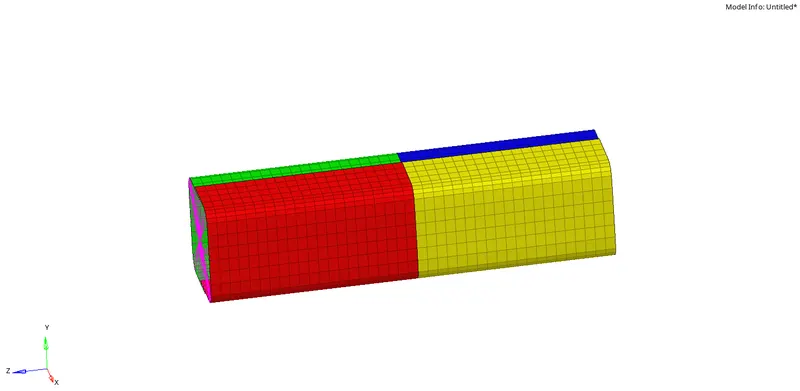
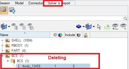
Step 2 : Removing both the notches and deleting boundary condition.
Removing Both the noches by using Align Nodes Panel.
Deleting boundary condition :
Step 3 : Simulating model
Analysis>Radioss>save as input Case_4_Crush_Tube_0000.rad file>Checkbox include collectors>Write (-nt 4) in options>Click Radioss
Step 4 : Switch to Hyper view
Step 5 : Select local model and result Case_4_Crush_Tube.h3d file
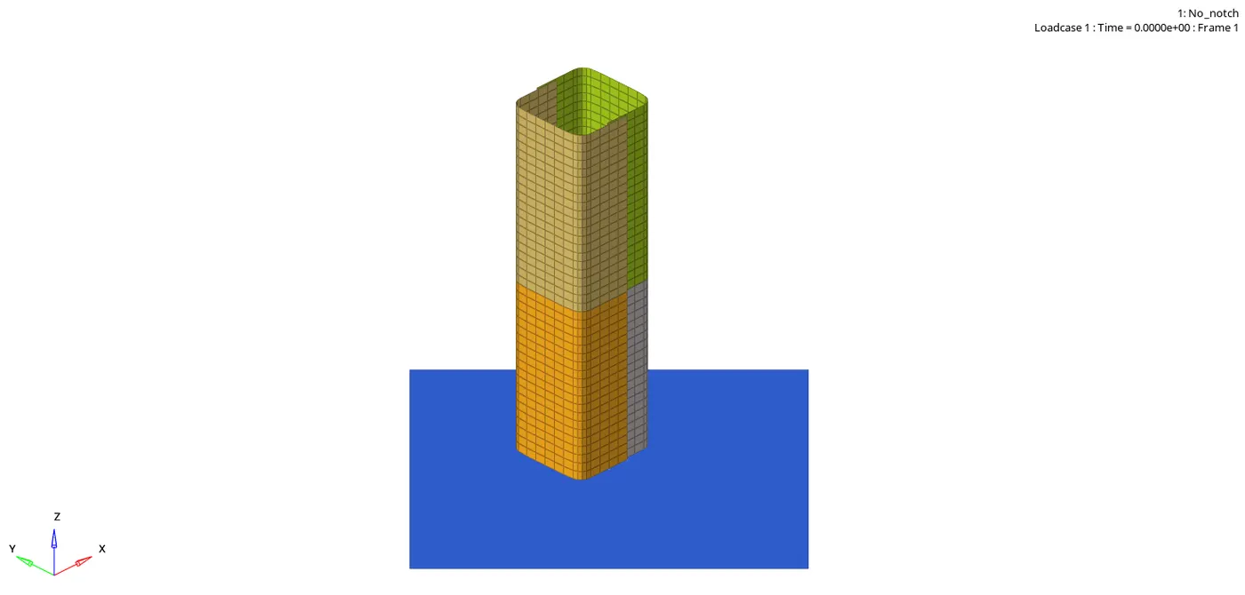
- Von-mises contour
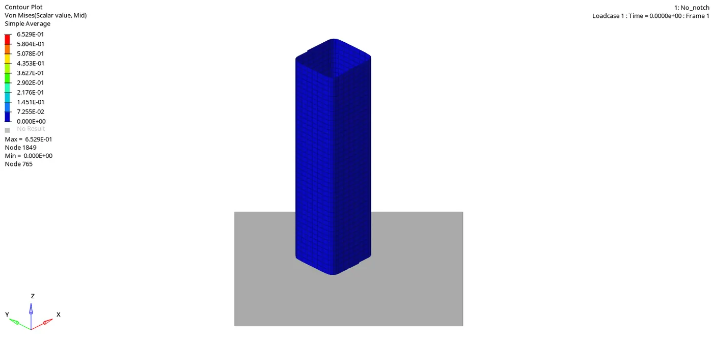
Step 6 : Checking the number of cycles it takes, energy error, mass error and simulation time.
- Number of cycles = 268738
- Energy error = -2.3 %
- Mass error = 0.0
- Simulation time = Starter+Engine run time = 458.37 s
Step 7 : Observing Kinetic,Internal,Contact and Total energy. Switch to Hypergraph 2D, upload Case_4_Crush_TubeT01
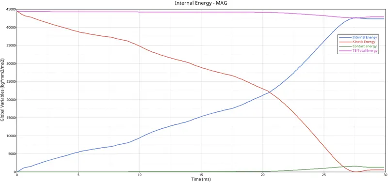
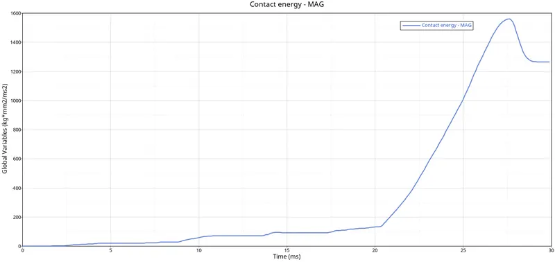
Step 8 : Observing Rigid Wall Forces
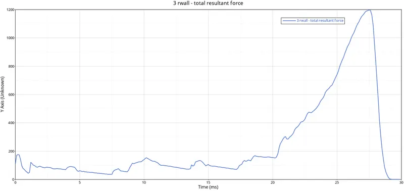
Case 5 : Creating a new notch in the middle, and running with whole section.
Step 1 : Open Hyperworks in Radioss solver. Import Solver desk Case_4_Crush_Tube_0000.rad file
Step 2 : Creating a new notch in the middle of the whole component.
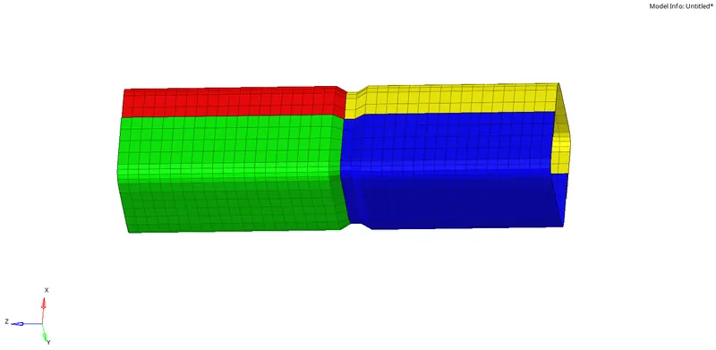
Step 3 : Simulating Model
Analysis>Radioss>save as input Case_5_Crush_Tube_0000.rad file>Checkbox include collectors>Write (-nt 4) in options>Click Radioss
Step 4 : Switch to Hyper view
Step 5 : Select local model and result Case_5_Crush_Tube.h3d file
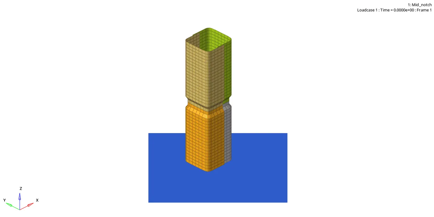
- Von-mises contour
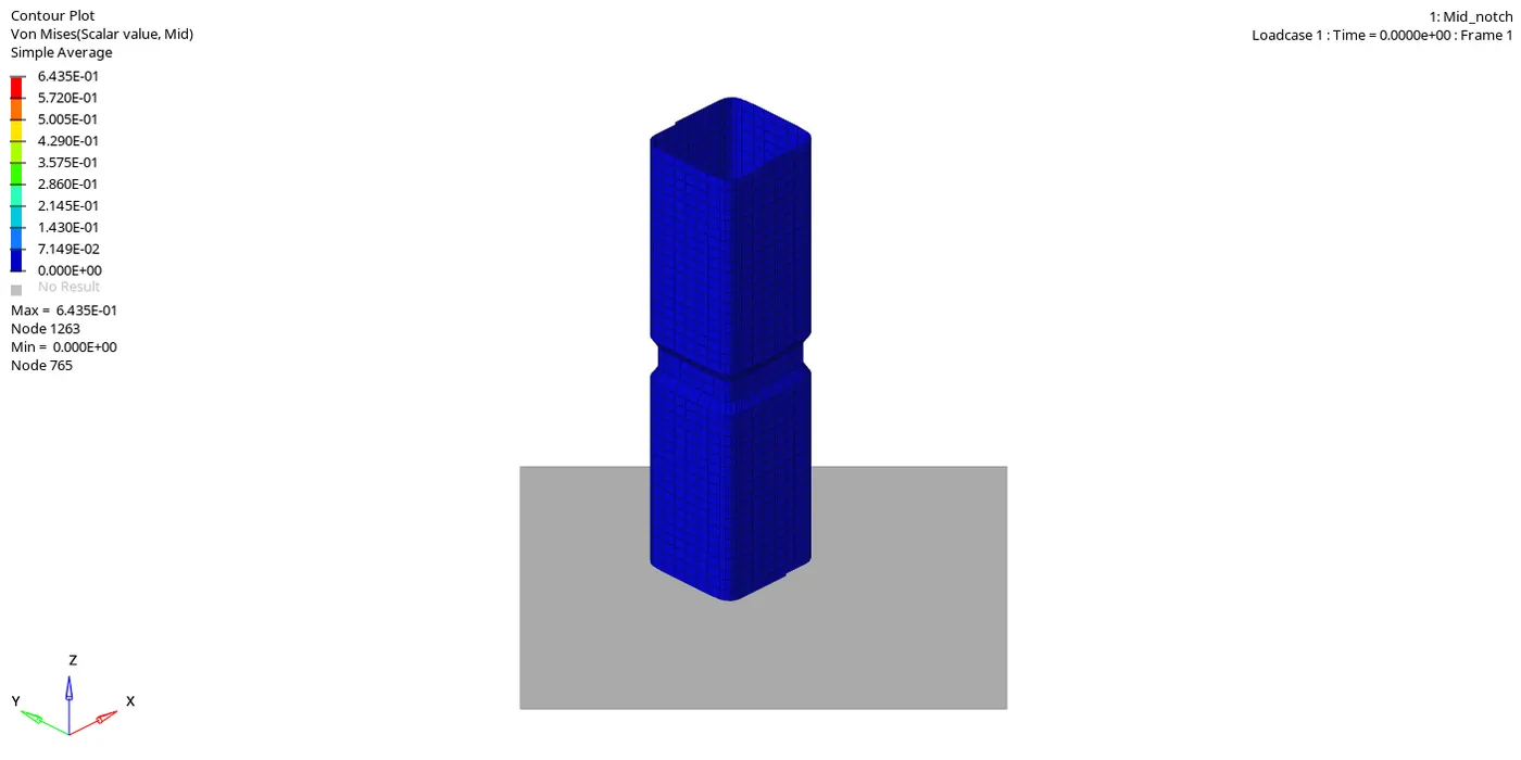
STEP 6 : Checking the number of cycles it takes, energy error, mass error and simulation time.
- Number of cycles = 265789
- Energy error = -1.8 %
- Mass error = 0.0
- Simulation time = Starter+Engine run time = 463.33s
STEP 7 : Observing Kinetic,Internal,Contact and Total energy. Switch to Hypergraph 2D, upload Case_5_Crush_TubeT01
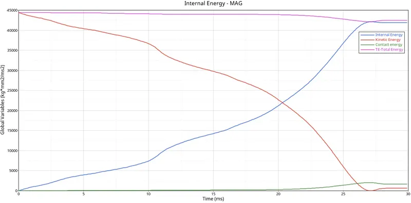
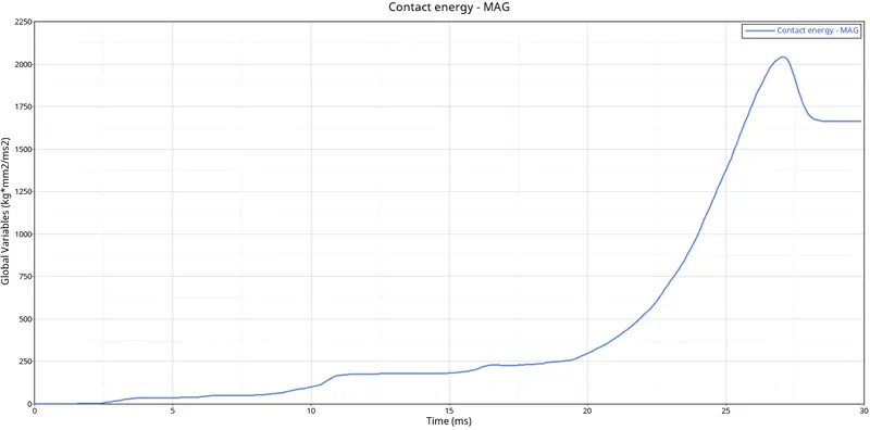
Step 8 : Observing Rigid Wall Forces
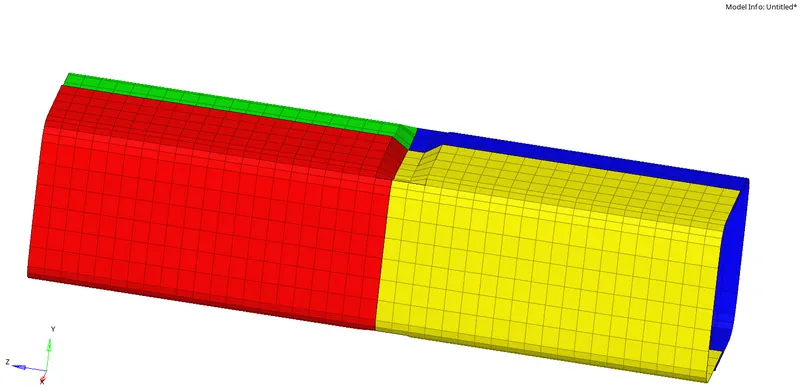
Case 6 : Create a notch with nodes only from opposing 2 faces and running simulation.
Step 1 : Open Hyperworks in Radioss solver. Import Solver desk Case_5_Crush_Tube_0000.rad file
Step 2 : Creating a new notch on opposite two faces of the component.
Step 3 : Simulating model
Analysis>Radioss>save as input Case_6_Crush_Tube_0000.rad file>Checkbox include collectors>Write (-nt 4) in options>Click Radioss
Step 4 : Switch to Hyper view
Step 5 : Select local model and result Case_6_Crush_Tube.h3d file
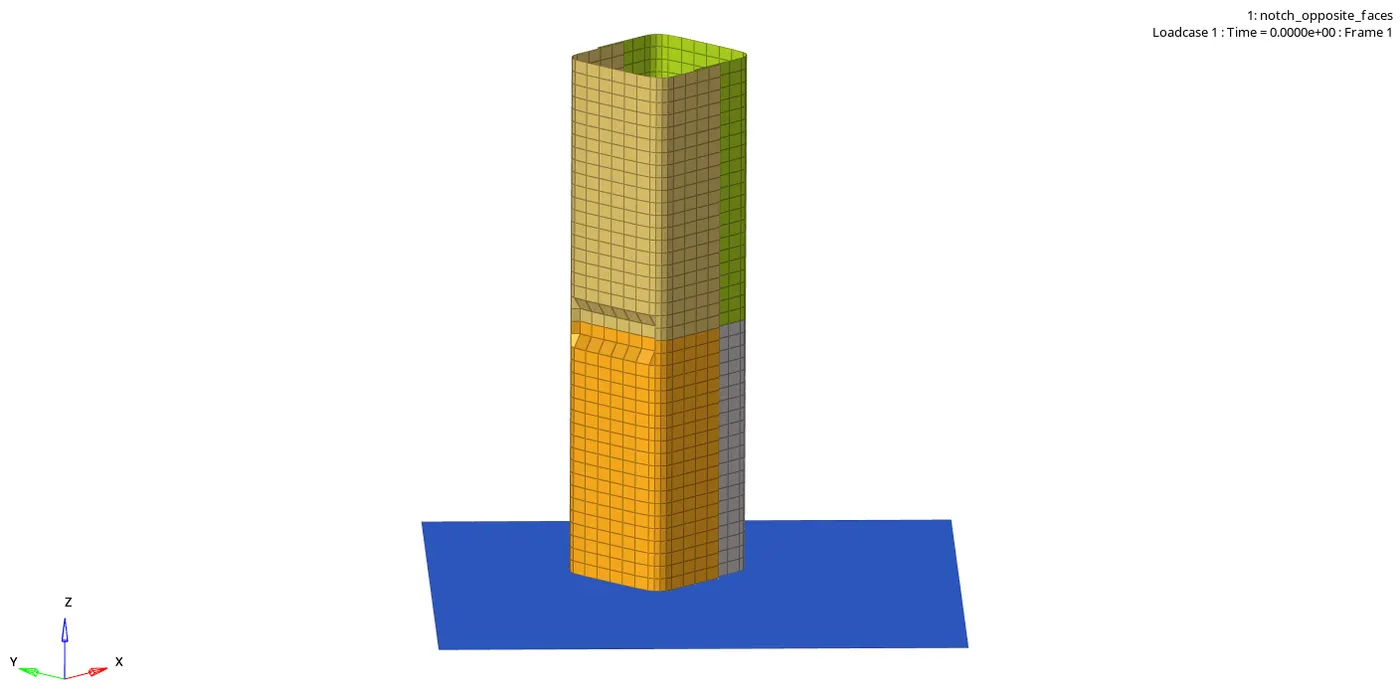
- Von-mises contour
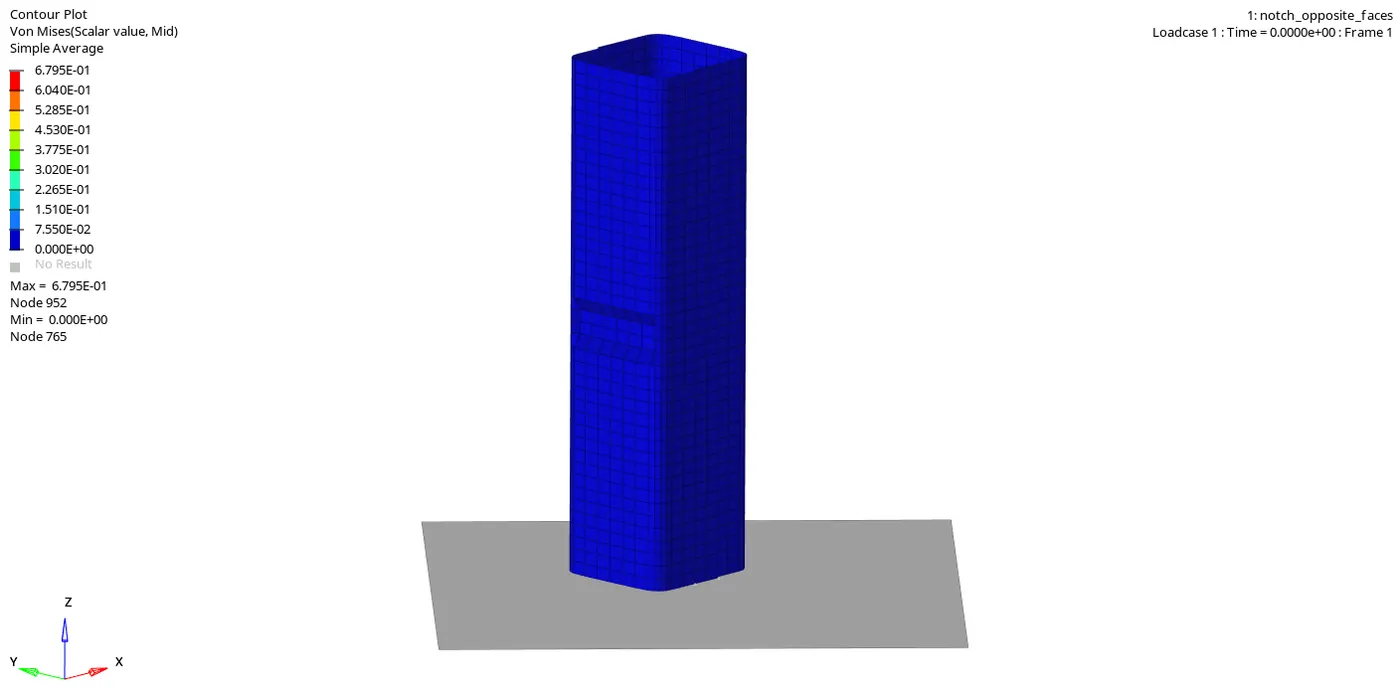
Step 6 : Checking the number of cycles it takes, energy error, mass error and simulation time.
- Number of cycles = 365188
- Energy error = -2.1%
- Mass error = 0.0
- Simulation time = Starter+Engine run time = 639.73 s
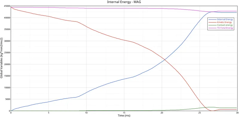
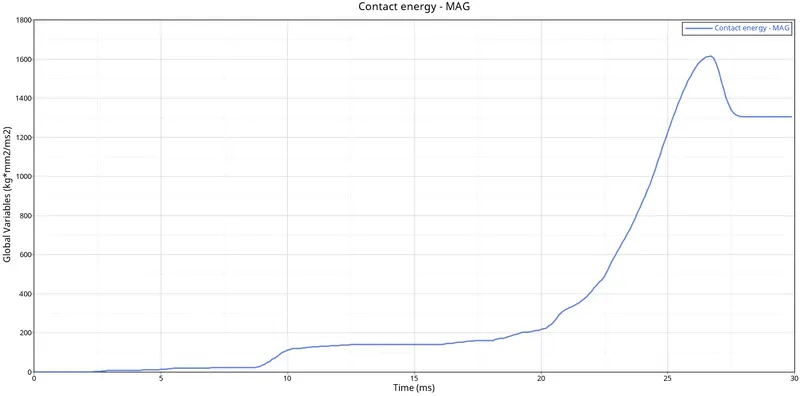
Step 7 : Observing Kinetic,Internal,Contact and Total energy. Switch to Hypergraph 2D, upload Case_6_Crush_TubeT01
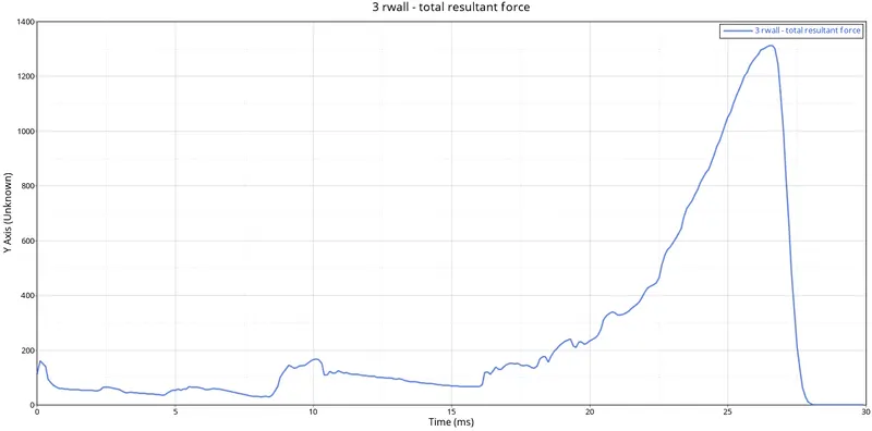
Step 8 : Observing Rigid Wall Forces
Observations :
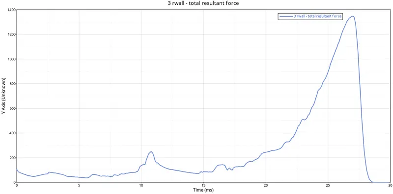
Case 1 : In case 1, notches are away from the middle of the component and four more notches are made on the same side of each corner. Total resultant forces reach a peak of 1350KN at 26.5 seconds and Kinetic energy and internal energy intersect each other at 22500 KN at 21 seconds.
Case 2 : In case 2 we won’t find any differences after changing it to Inacti=6, we didn’t make changes to the structure of the crush tube, The results we got were almost the same as case 1.
Case 3 : In case 3 we created the type 11 contact, we didn’t make changes to the structure of the crush tube, We saw that total resultant force was decreased to 1200KN at 27 seconds. Here also Kinetic energy and internal energy intersect each other at 22500 KN at 21 seconds.
Case 4 : In case 4 we removed both the notches from the crush tube, so there was no notches in the component it was completely align, we saw that there is sudden increase of total resultant force after 0 seconds and then it reaches peak at 1000KN at 28 seconds, we also saw that there was disturbance in resultant tangent force in the rigid wall graph between 15 to 30 seconds. Here also Kinetic energy and internal energy intersect each other at 22500 KN at 21 seconds.
Case 5 : In case 5 we make a notches in the middle around the component we saw again there is increases in total resultant forces than earlier case with 1210KN at 27.5 seconds
Case 6 : In case 6 we make more notches in the opposite face of the component, we saw that there is sudden increases in total resultant force at 10 second due to opposite notches which we didn’t found in earlier cases but peak of total resultant force again decreased to 1020KN at 27.5 seconds, here kinetic energy and Internal energy intersect each other at just 20 seconds at 20 seconds with 22500KN force, which also we didn’t saw in earlier cases.
| No. of Cycles | Energy Error | Mass Error | Simulation Time | |
| Case 1 | 83496 | -3.80% | 0 | 140.16 s |
| Case 2 | 83496 | -3.80% | 0 | 139.47 s |
| Case 3 | 413904 | -3.10% | 0 | 706.74 s |
| Case 4 | 268738 | -2.3 % | 0 | 458.37 s |
| Case 5 | 265789 | -1.8 % | 0 | 463.33 s |
| Case 6 | 365188 | -2.10% | 0 | 639.73 s |
- Here in these simulations type 7 interface is used for first two cases and type 11 is created. These two interfaces work together making simulation more stable. The deformation of the tube is observed to be stable , where slave nodes try not eter the master gap, where the penalty method creates a spring and resistive forces are applied.
- In the second case, we only observe the simulation time changes, where the inacti 6 is set which performs initial penetration where it checks before the simulation starts.
- In third case, type 7 and type 11 interface work together so simulation time increases.
- In fourth case, we can see less no of cycles and lower energy mass error, where notches and boundary conditions are removed.
- In the fifth case, we observe increase in energy error due to the notch created at middle of section where the four components are closer to each other.
- In sixth case, we observe decrease energy error where opposite side of notches are created.
Conclusion :
Hence by performing this project that we have came to know that type 7 and type 11 can work together to increase the simulation stable. The presence and absence of notches and their effect on crashing the tube is studied. The important parameters which affect the simulation in its time are also stuided.
LEARNINGS:
- 2D Meshing
- Joining components with 2D spot weld connectors.
- Importing starter file runname_0000.rad file
- Using Radioss command
- Running runnane.h3D file in Hyperview to see animation
- Reading runname_0001.out file
- Using Hypergraph 2D.
- Observing energies graph
- Observing rigid wall forces.
- Changing Type 11 parameters.