Assignment 5-RADIOSS Interfaces & Study of Effect of Notches Challenge
Aim:
Create the mesh for bumper assembly withmesh size 6mm and run the Crash tube model with 6 different cases as given and compare the results
Objective:
- Run the crash tube model as it is.
- Change the Inacti=6 and run.
- Create the type 11 contact and run.
- Remove both notches and remove boundary condition on rigid body node then run.
- Create a new notch in the middle, select the whole section and run.
- Create a new notch with nodes only from opposing 2 faces and run.
PROCEDURE:
MESHING OF BUMPER
Import given model into hypermesh.It is seen that there is a lot of free edges in the model.
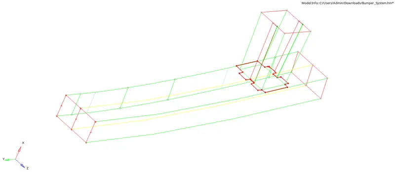
The model is cleaned up using various tools in Geom-quick edit .
After the model is cleaned up, ot is meshed using 2D-Automesh and give target element size as 6mm.
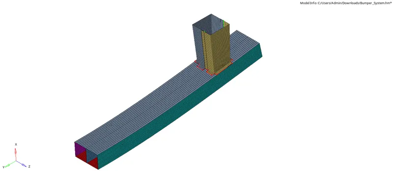
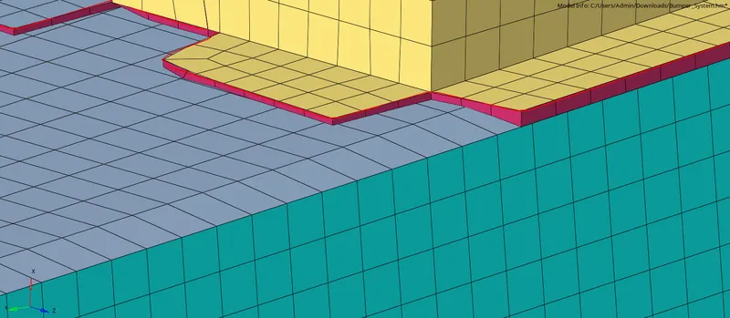
The model is meshed and is cleared of trias.After that connectors are used to connect the two components.
Go to 1D-connectors-seam and provide necesary values and connect the two components.
CASE 1:
In this case, we need to run the simulation on the crush tube as is.
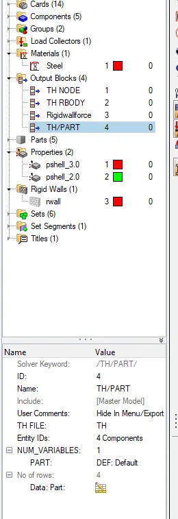
Go to the Analysis tab, Select the Radioss option > Select the location to save the file > Check include collectors box > In the options tab, type “-nt 4” > Click Radioss. Save the file in the localdirectory
The radioss runs and tadioss solver dialog box opens showing the energy error and mass error
Open hyperview to view animation and contour plots from H3d file.
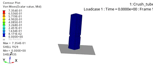
From the animation, it is seen that the deformation taking place at the middle notch first due to applied force
After the middle notch deforms the next deformation occurs in the second notch which is near to rigid wall this is because the thickness is less at bottom
The notch elements deforming inwards and the flat elements are bending outwards. This region does not require more force to deform the elements
It is due to the presence of notch leads to stress concentration in those areas. So the buckling occurs first in all the cases which have notches.
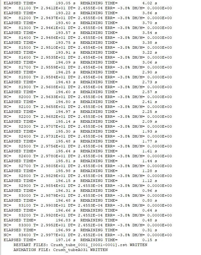
As we can see, the energy error is -3.8%. It is acceptable since it is below -15%. The mass error is zero
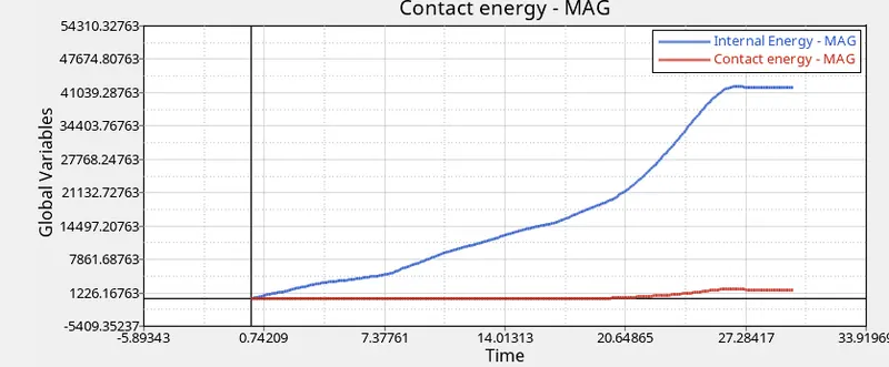
Internal energy keeps increasing because the crash tube continuously absorbs energy while crashing onto the rigid wall, which results in deformation. At the end when the deformation is complete the internal energy goes constant.
Contact energy is a type of energy that is created when one element comes in contact in with other elements. The opposing force created by the element is called contact energy. There is no contact initially so graph is constant.Eventually, the graph slightly increase due to the buckling of elements.
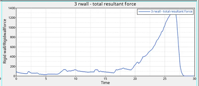
The rigid wall experiences stresses suddenly due to the crush tube crash in the rigid wall and absorb the energy from crush tube after the deformation completes, the rigid wall force is decreased immediately due to the energy transferred completely.
CASE 2:
Import the rad file and edit the inacti = 6 value in hypermesh .
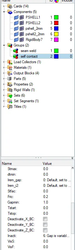
Go to the Analysis tab, Select the Radioss option > Select the location to save the file > Check include collectors box > In the options tab, type “-nt 4” > Click Radioss. Save the file in the localdirectory
The radioss runs and tadioss solver dialog box opens showing the energy error and mass error
Open hyperview to view animation and contour plots from H3d file.
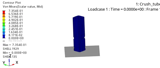
There isn't much difference between case 1 and case 2 animations. Even after the Inacti parameter was changed, it didn’t have any effect on the simulation as there was no initial penetration to manage in the first place. 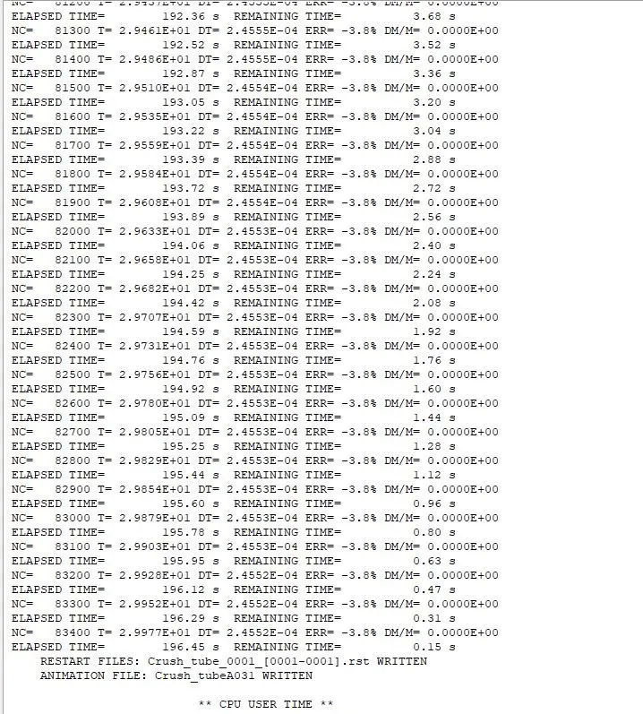
.The energy error is the same -3.8% also the same mass error of 0.
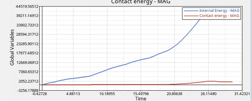
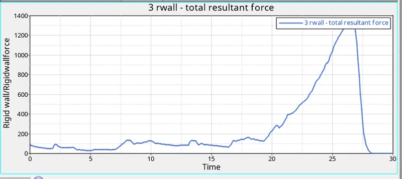
There isn't any difference in the graphs in comparison to case 1,there is no initial penetration since there is no difference between case 1 and case 2 energy plots since the simulation was modified to detect such penetrations through the inacti function. If initial penetrations existed, internal energy would start from a non-zero value.
The forces being plotted in the Rigid Wall Forces are the Forces applied to the crush tube by the Rigid Wall. The contact energy increases simultaneously rigid Wall forces will also increase and the Rigid Wall Forces also decrease at the point where the Contact energy flat and finally when the model loses contact with the Rigid Wall, the Rigid Wall Forces become Zero
CASE 3:
In this case, we need to input type 11 interface to the case 2 solver deck file. After importing it in Hypermesh, Right-clicking the section, we can select Create >> Contact. After that, we can define this newly created contact and assign it the following values as shown
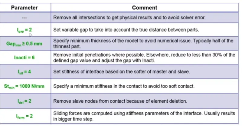
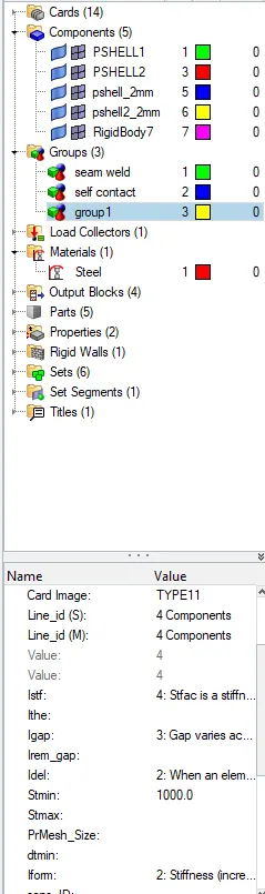
For both Line_id (S & M) attributes, all the components of the model will be selected. The other values are recommended settings for Type 11.
Go to the Analysis tab, Select the Radioss option > Select the location to save the file > Check include collectors box > In the options tab, type “-nt 4” > Click Radioss. Save the file in the localdirectory
The radioss runs and tadioss solver dialog box opens showing the energy error and mass error
Open hyperview to view animation and contour plots from H3d file.
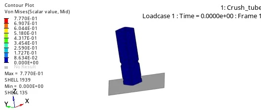
Here, the deformation characteristics are like what was observed in previous cases.
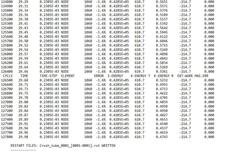
Energy error is still within the -15% limit at -1.6% Mass error is non-existent.
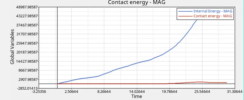
The internal energy increases with time as the tube contacts the rigid wall. There is a peak and a plummet at around 25 seconds, which is the time when the crush tube is completely crushed and no more energy can be absorbed.
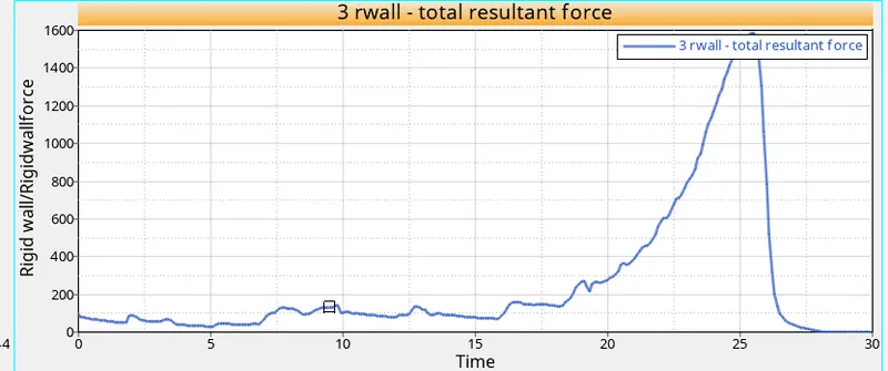
There is no difference between the energy and rigid wall plots of this case and previous cases.
Case 4:
Import the 0000.rad file. Then remove the notch in the model using Align option. select reference nodes as 1st node and 2nd node, after that select the nodes that need to be aligned. Now select align and make sure no notch is present in the model.
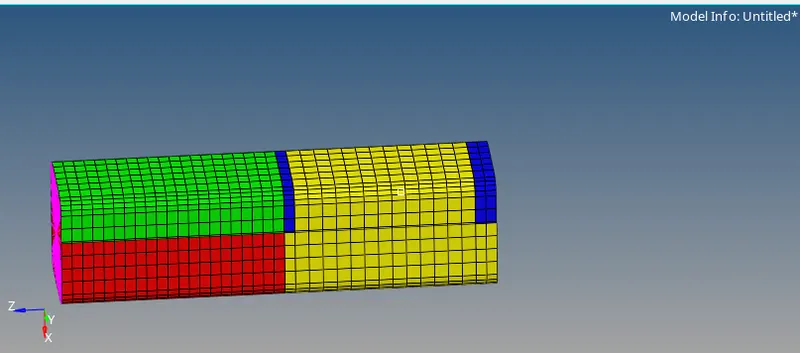
To delete the Boundary conditions, go to the Solver Deck, If the Solver deck is not visible, Go to the View tab in the Standard menu bar > Click Browse > Click Hyper Mesh > Click on Solver > The Solver Deck will be opened. > Delete the BCS Entity in the Solver Deck.
Go to the Analysis tab, Select the Radioss option > Select the location to save the file > Check include collectors box > In the options tab, type “-nt 4” > Click Radioss. Save the file in the localdirectory
The radioss runs and tadioss solver dialog box opens showing the energy error and mass error
Open hyperview to view animation and contour plots from H3d file.
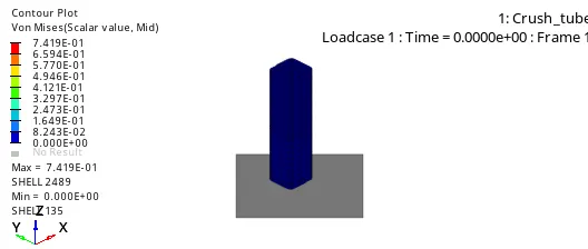
After that, the graphs are plotted
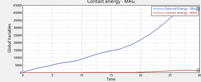
Internal energy keeps increasing at some point due to the buckling of the tube. More energy is absorbed by the tube when deformation takes place that's why the internal increases after some point. Contact energy slightly decreased eventually due to the absence of notches.
Next is to plot rigid wall resultant force graph for case 4 simulation, so select variable as rigid wall and parameter as resultant force and apply to plot the graph.
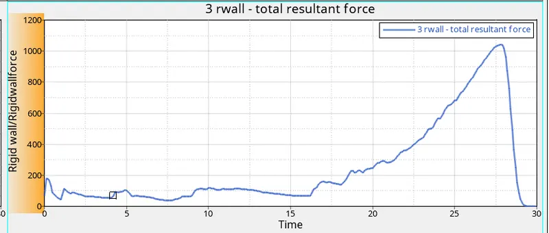
In this case, the RWALL force graph peaks after some point due to a large amount of force is transferred to the rigid wall during the collision of the crush tube. After the deformation was completed, the graph decreases and gets to a constant value after the deformation.
CASE 5:
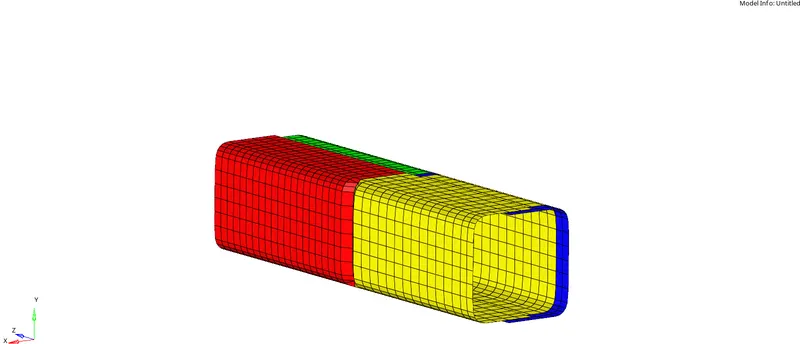
In this case the starter file of case 4 is imported .There are no notches or boundary conditions in model.create a notch through the middle section of the crush tube using the translate tool in Hypermesh. Go to tools > translate.
We can either select elements or nodes to translate. After assigning the direction of translation assign a magnitude of 5. The click 'translate+' or 'translate-'.
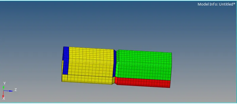
Go to the Analysis tab, Select the Radioss option > Select the location to save the file > Check include collectors box > In the options tab, type “-nt 4” > Click Radioss. Save the file in the localdirectory
The radioss runs and tadioss solver dialog box opens showing the energy error and mass error
Open hyperview to view animation and contour plots from H3d file.
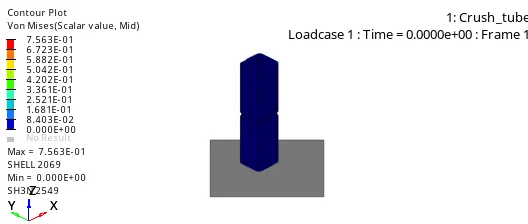
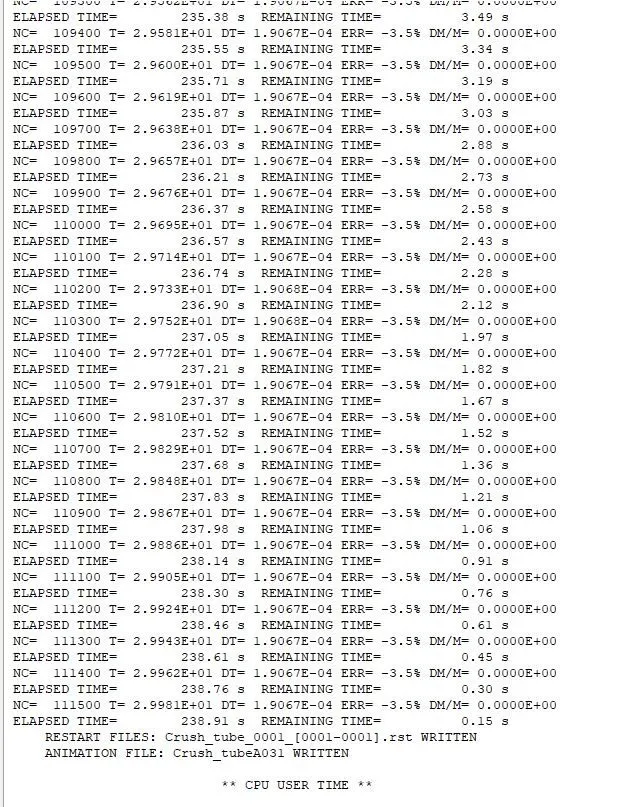
Energy error is still within the -15% limit at -3.5%. Mass error is non-existent
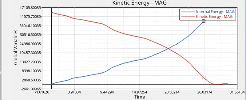
Internal energy keeps increasing due to the deformation that takes place. The contact energy slightly changed initially and because of the depth of the notch increased compared to previous cases.
There isnt considerable change between case 4 and case 5. Eventually, rwall force peaks at some value due to the intake of energy created during collision and when the tube crushed completely, the value decreases and gets constant
 .
.
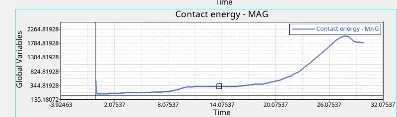
In this case, the contact energy is more when compared to case 1 and case 2. This is due to the reason there is only one notch at the center which increases the rate of deformation, which increases the rate of penetration.
There is a change in the internal energy because as there is a notch only at the middle. The elements will be impacted without any deviation, as of in the previous cases in which the notch is present at the beginning. There will be a drop in the internal energy at the middle and there will be a rise again. In this case the notch prevents the model to rise back again as compared to previous
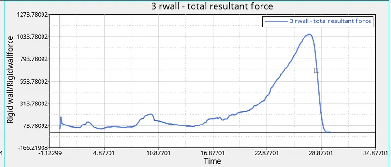
The fluctuations in the beginning is due to because of the notch and the edges of the elements come into contact gradually from the beginning and continue to reach their peak value and then the graph drops when there is impact and becomes constant.
Case 6: .
Import the 0000.rad file .
Use translate option as in the earlier cases to create notches on the opposite faces .
Go to the Analysis tab, Select the Radioss option > Select the location to save the file > Check include collectors box > In the options tab, type “-nt 4” > Click Radioss. Save the file in the localdirectory
The radioss runs and tadioss solver dialog box opens showing the energy error and mass error
Open hyperview to view animation and contour plots from H3d file.
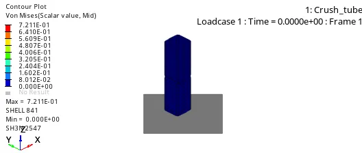
The buckling occurs at first in the region where the notch is present, after that lower part of the tube is deformed. Finally, the upper part deformes completely after some point.
Now open the 0000.out file in file directory to check the energy errors, no. of. cycles and elapsed time in the simulation file.
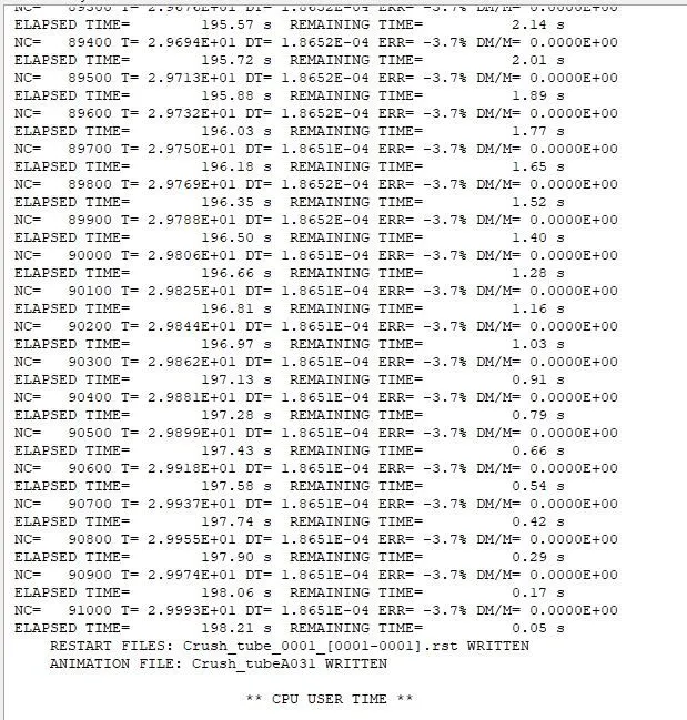
the energy error is -3.7% and it is acceptable since it is below -15%. there is no mass error 0%.
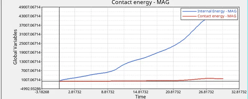
the internal energy increases due to the deformation and the contact energy also increases due to the depth of the notch.
plot rigid wall resultant force graph for case 6 simulation, so select variable as rigid wall and parameter as resultant force and apply to plot the graph.
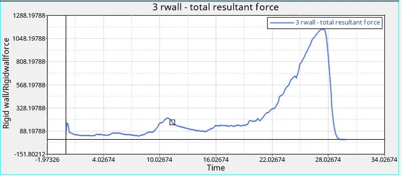
The plotted RWALL graph is similar like previous case. In this case, the peak value is slightly decreased due to the presence of notch only in opposing faces. After buckling process, the peak value drops to lesser and got constant after the tube crushed completely .
Conclusion:
The Bumper model have been meshed and seam welded with the element size of 6mm .Observing the cases it is noticed that criteria Inacti is necessary to be defined as it removes any initial intersections in the model .The type 11 contact requires lesser parameters to be defined and also takes lesser time to be simulate compared to type 7 contact. Notches are an important part of the model that helps in directing deformation and buckling when a load is applied. The component with notch absorb maximum energy when a load is applied.