Assignment 5
AIM:
To do "MESHING" on the given "BUMPER ASSEMBLY" with mesh size of "6mm" and To run the given "CRASH TUBE MODEL" according to the given data through 6 different cases.
OBJECTIVE:
Create the mesh for bumper assembly,mesh size should be 6mm.
- Run the crash tube model as it is.
- Change the Inacti=6 and run.
- Create the type 11 contact and run.
- Remove both notches and remove boundary condition on rigid body node then run.
- Create a new notch in the middle ,select the whole section and run.
- Create a new notch with nodes only from opposing 2 faces and run.
- Plot RWALL forces ,contact forces and internal energy.
- Create "TH/PART" for all parts and compare results for all cases.
PROCEDURE:
CREATING MESH FOR BUMPER ASSEMBLY WITH GIVEN MESH SIZE = "6mm"
STEP-1:
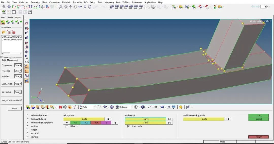
HERE WE HAVE TO DO THE GEOMETRY CLEAN UP OF THE GIVEN BUMPER MODEL AND WE HAVE DONE THE FOLLOWING:
- Surface trimming, By going to "Geometry" > "Surface Edit" > "Trim with surface or planes".
- Add or remove points, By going to "Geometry" > "Quick Edit" .
- Replace points, By going to "Geometry" > "Quick Edit" .
- Toggle Edge, By going to "Geometry" > "Quick Edit".
STEP-2:
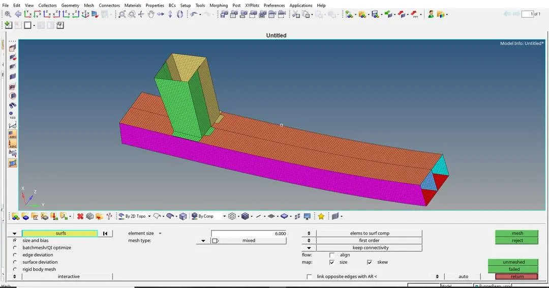
WE HAVE TO MESH THE WHOLE AS "BUMPER ASSEMBLY" AS SHOWN BELOW:
IMAGE-1:
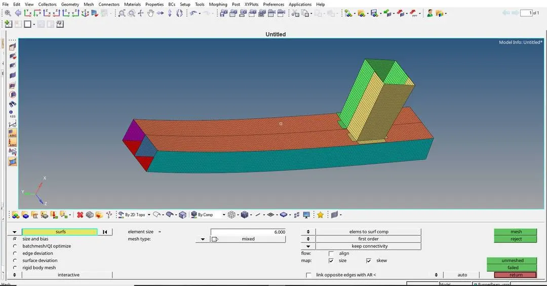
IMAGE-2:
STEP-3:
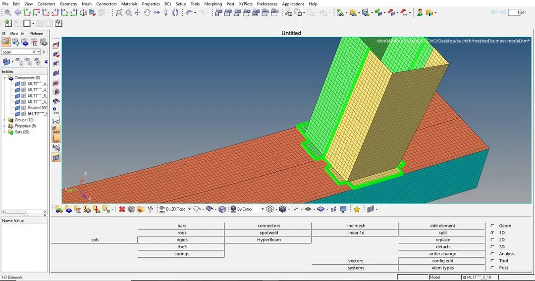
HERE WE HAVE TO DO WELD CONNECTIONS BETWEEN TWO DIFFERENT COMPONENTS WITH "RIGID SEAM WELD CONNECTIONS" AS SHOWN BELOW:
TO DO SEAM WELD, WE HAVE TO GOTO: "1D" > "Connectors" > "Seam" > "In location we have to click on 'Node list', in this we have to choose 'Node path' " > "In Type we have to choose ' Type2 (Spring single row)' ", AS SHOWN BELOW:
IMAGE-1:
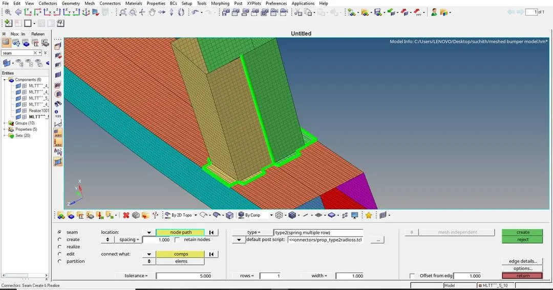
IMAGE-2:
CASE-1:
RUNNING THE GIVEN MODEL AS IT IS BY IMPORTING "Crash_tube_0000.rad" TO SOLVER DECK:
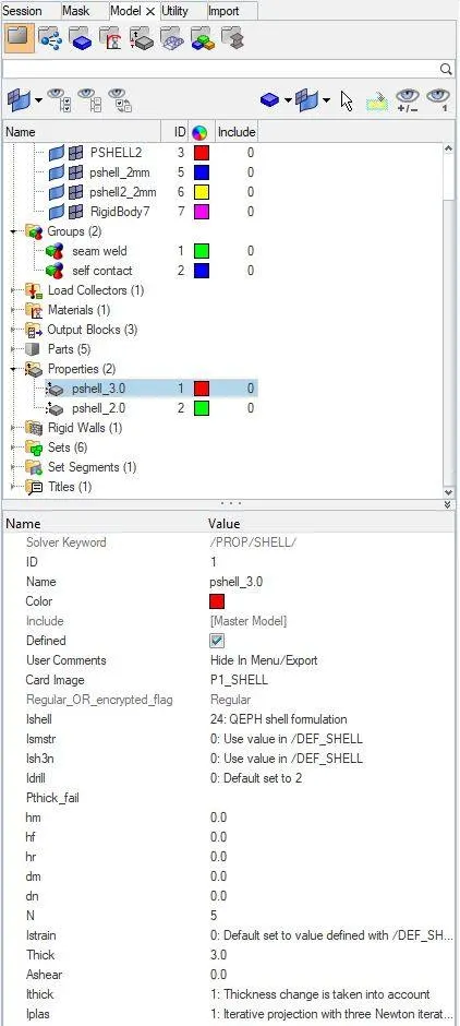
DEFAULT PROPERTY CARD IMAGE OF "PSHELL 2.0":
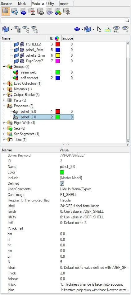
DEFAULT PROPERTY CARD IMAGE OF "PSHELL 3.0":
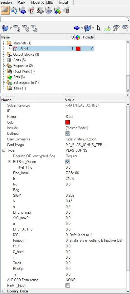
DEFAULT MATERIAL CARD IMAGE: HERE "M2_PLAS_JOHNS" HAS BEEN USED AS MATERIAL CARD AS SHOWN BELOW:
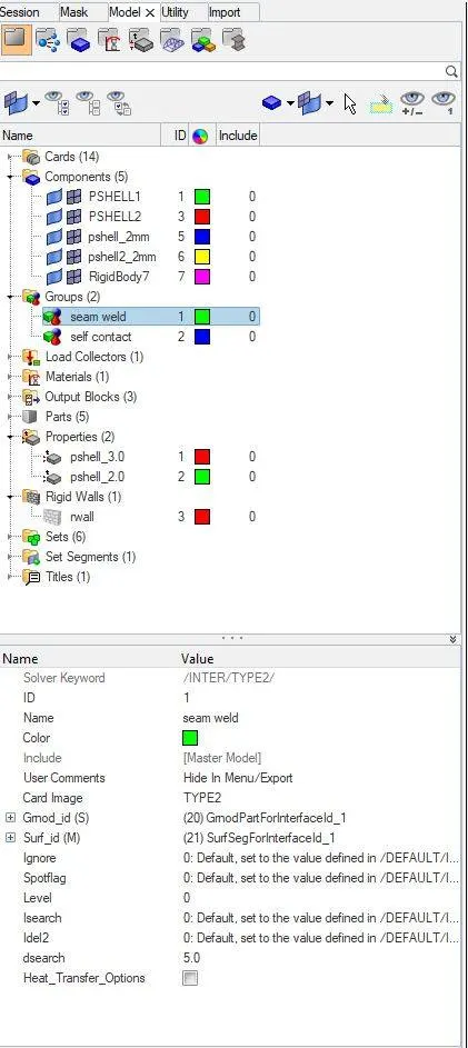
DEFAULT GROUP CARD OF "SEAM WELD" WHICH SHOWS DETAILS OF "TYPE-2"INTERFACE :
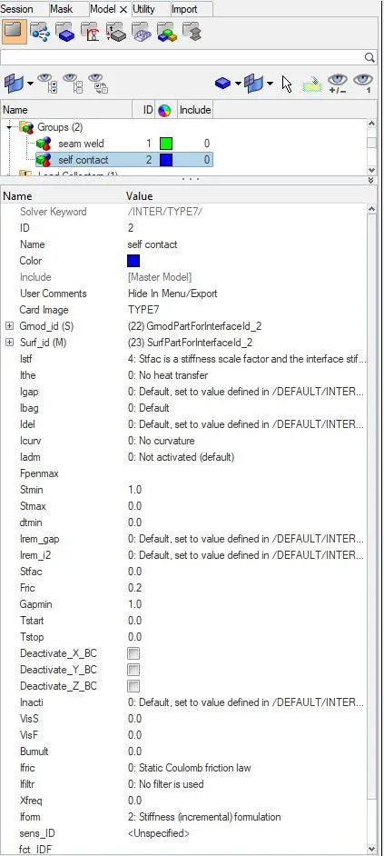
DEFAULT GROUP CARD OF "SELF CONTACT" WHICH SHOWS DETAILS OF "TYPE-7" INTERFACE :
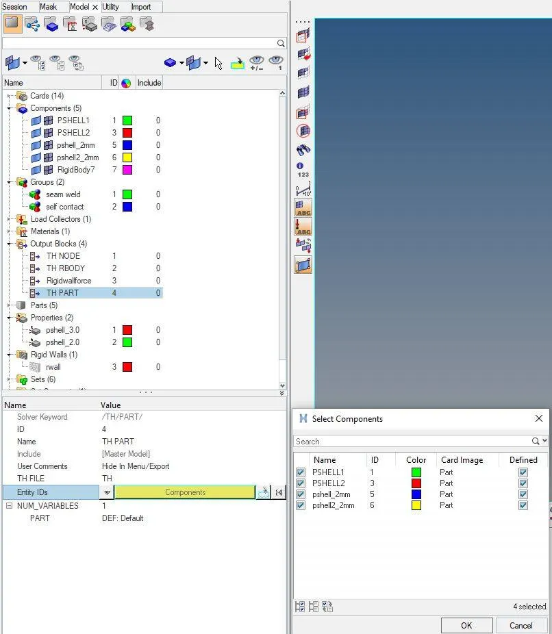
CREATING "TH/PART" FOR ALL PARTS IN THE "OUTPUT BLOCKS":
AFTER CREATING "TH/PART" FOR ALL PARTS IN THE "OUTPUT BLOCKS":
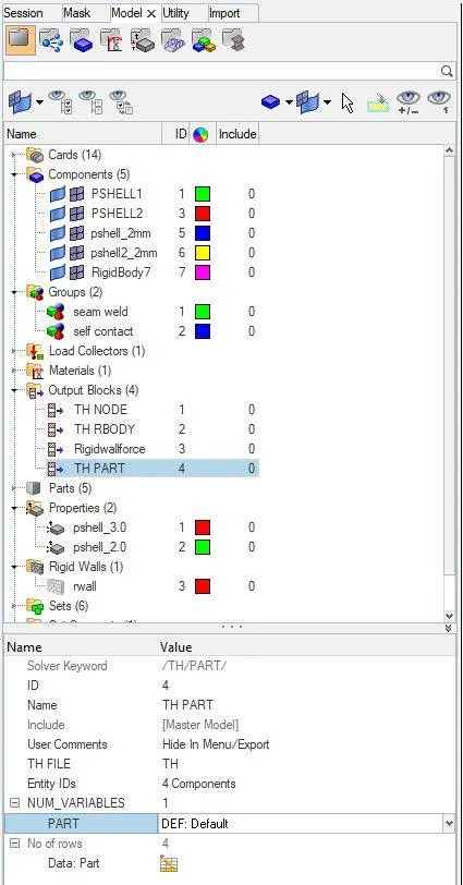
THIS ABOVE CARD HELPS IN ANALYSING THE ENERGIES ABSORBED IN EACH PART, THIS CAN BE DRAWN OUT WITH THE HELP OF "HYPERGRAPH" AS SHOWN BELOW:

WE HAVE TO NOW START THE SIMULATION BY CLICKING ON TO "ANALYSIS" > "RADIOSS"
RESULTS OF CASE-1 :
ERRORS ARE AS SHOWN BELOW:
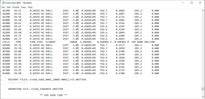
FROM THE ABOVE RESULT WE GET:
ENERGY ERROR =-3.8% (Here the energy error is in permissible range, so we can move forward)
MASS ERROR = 0
NUMBER OF CYCLES = 83496
TOTAL ELAPSED TIME = 137.80sec
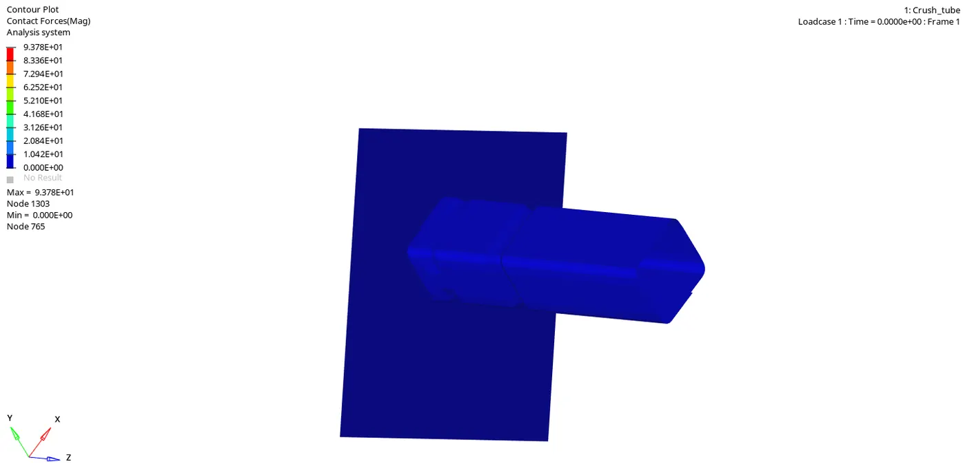
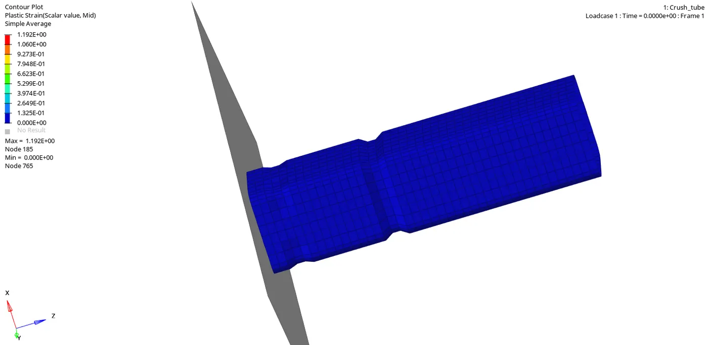
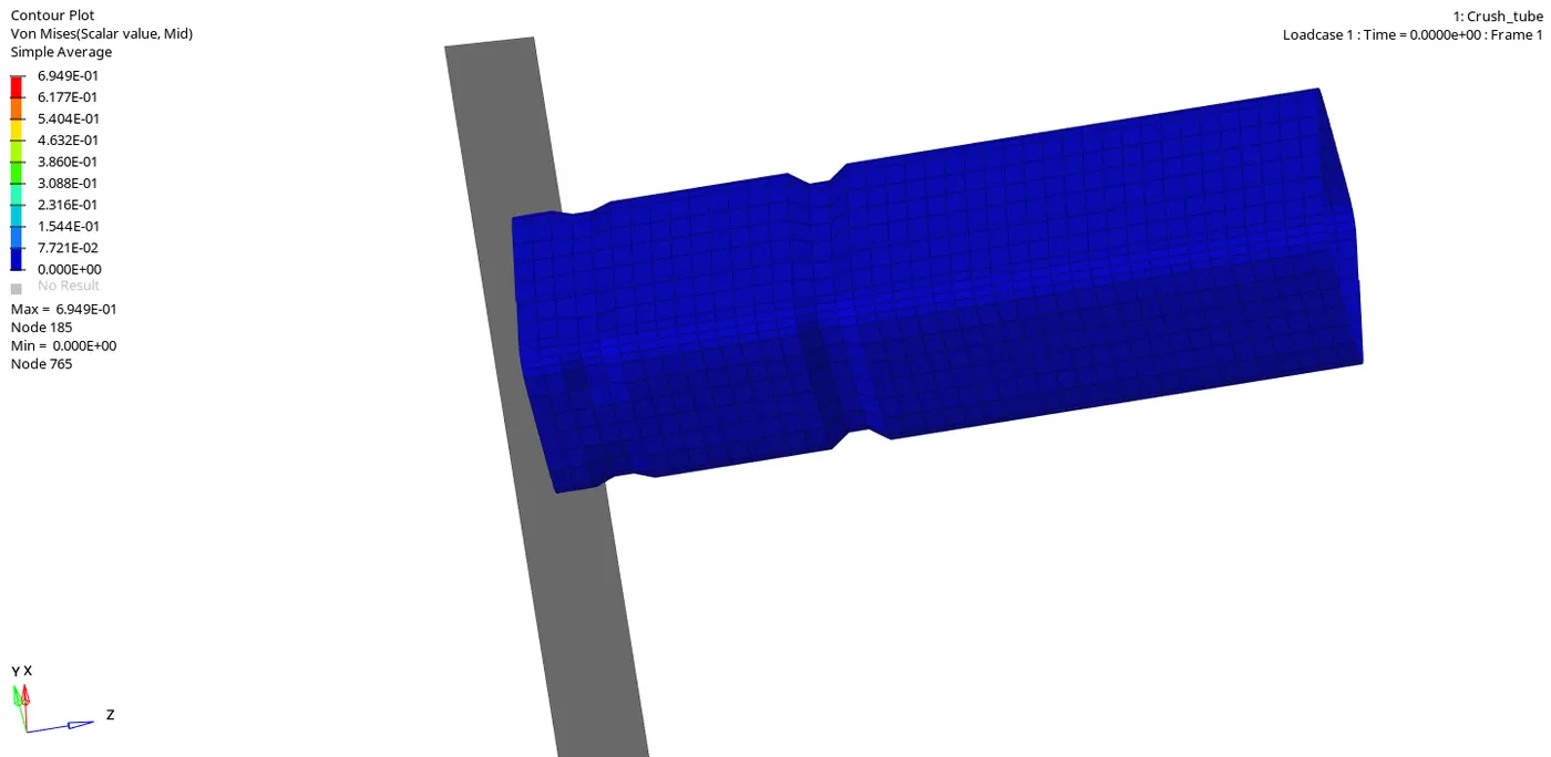
WE HAVE TO OPEN "h3d" FILE IN HYPERVIEW TO SEE THE ANIMATIONS AS SHOWN BELOW:
CONTACT FORCE SIMULATION:
PLASTIC STRAIN SIMULATION:
VONMISES SIMULATION:
NOW WE HAVE TO OPEN A "TO1" FILE IN "HYPERGRAPH" TO PLOT ALL THE ENERGIES AS SHOWN BELOW:
"INTERNAL ENERGY" AND "CONTACT ENERGY" PLOTS:
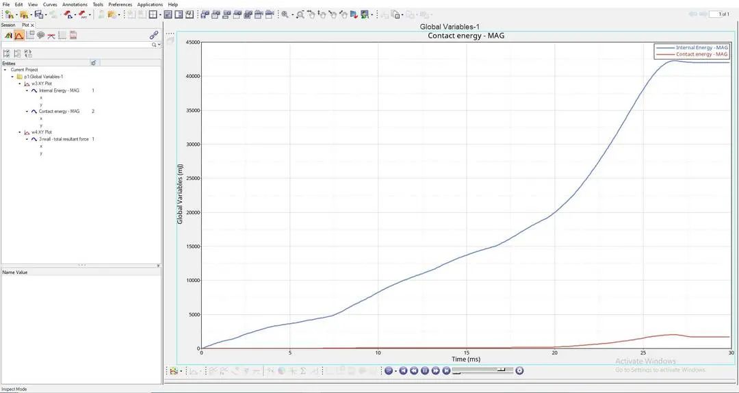
EXPLAINATION OF THE ABOVE ENERGY GRAPH:
- "INTERNAL ENERGY PLOT" : This Internal Energy or Strain Energy keeps on increasing due to the Increase in deformation of the "CRASH TUBE" untill the whole tube ruptures at a point, and after reaching this rupture point the Internal Energy is constant, this is because there will be a decrease in the Internal Energy, at this point elements stop absorbing energy, this is because plastic deformation has already happened, at this point all the elements would have experienced the "Ultimate plastic strain" and would have been deformed completely. This happens till it reaches "27.5th second".
- Here in the above graph, "INTERNAL ENERGY" is not increasing "LINEARLY", That is the graph of "INTERNAL ENERGY" is "NON-LINEAR", this is because "CRASH-TUBE" is made up of "4-SHELLS", among them "2-SHELLS" are of thickness "3mm" and the other "2-SHELLS" are of thickness "2mm".
- As per the above graph, "INTERNAL ENERGY" will be "CONSTANT" after "27.5th second".
- Here "MAXIMUM INTERNAL ENERGY" just below "42500 milli joule".
- "CONTACT ENERGY PLOT" : From "0th second" to "7.5th second" , "2-SHELLS" of "2mm" thick is in contact with "RIGID-BODY", But after This contact energy slightly increases after "7.5th second", at this point "2-SHELLS" of "3mm" thick is being compressed and drastically increases after "20th second", here contact force is high because at this point the whole "CRASH-TUBE" elements come in contact with the "RIGID-BODY", That means the whole component is being compressed totally, to crash this we need more force, so here the "CRASH-TUBE" needs more "CONTACT FORCE", hence experiences more "CONTACT ENERGY".
- Here at this point the whole component comes in contact with "RIGID BODY" and "SELF-CONTACT" of the "CRASH-TUBE" is happening here, so "CONTACT ENERGY INCREASES" at this point.
- After "27.5th second", "CONTACT ENERGY" is constant, At this point the whole "CRASH-TUBE" will be crushed completely and this completely crushed "CRASH-TUBE" will no longer be in contact with "RIGID-WALL", which means this completely crushed "CRASH-TUBE" will get detached from the "RIGID WALL", so there will be no "CONTACT ENERGY" experienced by "CRASH-TUBE" component for "2.5 seconds" as shown in the above graph.
- Here "MAXIMUM CONTACT ENERGY" is near to "2000 milli joule".
"RIGID WALL FORCES" PLOT:
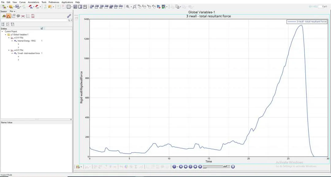
EXPLAINATION OF THE ABOVE RIGID WALL FORCE GRAPH:
- "RIGID-WALL FORCES PLOT" : This is the plot which shows the "IMPACT FORCE" experienced by the "RIGID-WALL", here "CRASH TUBE" is Impacting on the "RIGID-WALL".
- As per the above graph untill this "20th second", "RIGID BODY" will be experiencing forces from the "CRASH-TUBE"component, After this the "RIGID BODY" force will increase drastically, this is because at this stage "RIGID BODY" will experience more "CONTACT FORCE" from the "CRASH-TUBE", so to avoid this "CRASH TUBE" from penetrating into the "RIGID WALL", This "RIGID WALL" will induce maximum "RIGID WALL FORCES" to avoid "SLAVE NODES" from penetrating into the "MASTER NODE".
- After "27.5th second" the "RIGID WALL FORCES" will decrease and come to "0", this is because "CRASH-TUBE" will no longer be in contact after "27.5th second" as shown in the above graph.
- Here "MAXIMUM RIGID WALL FORCE" Reach to "1350KN".
CASE-2:
RUNNING THE GIVEN MODEL BY IMPORTING "Crash_tube_0000.rad" TO SOLVER DECK:
"MATERIAL CARDS" AND "PROPERTY CARD" WILL BE IN DEFAULT, SAME AS IN THE ABOVE CASE:
HERE WE CHANGE THE VALUES OF SELF CONTACT INTERFACE (TYPE-7) IN GROUPS TO THE "RECOMMENDED VALUES" AS SHOWN BELOW:
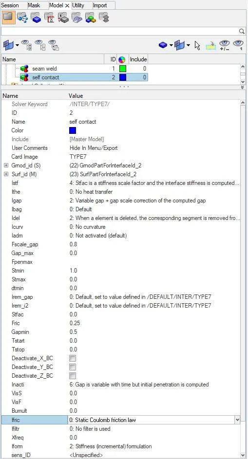
This "Inacti=6" helps us to identify and removes if there is any "SLAVE NODE" is initially interacting or penetrating the "MASTER SEGMENT".
WE HAVE TO NOW START THE SIMULATION BY CLICKING ON TO "ANALYSIS" > "RADIOSS"
RESULTS OF CASE-2 :
ERRORS ARE AS SHOWN BELOW:
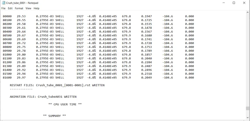
FROM THE ABOVE RESULT WE GET:
ENERGY ERROR =-4.8% (Here the energy error is in permissible range, so we can move forward)
MASS ERROR = 0
NUMBER OF CYCLES = 81699
TOTAL ELAPSED TIME = 163.31 sec
WE HAVE TO OPEN "h3d" FILE IN HYPERVIEW TO SEE THE ANIMATIONS AS SHOWN BELOW:
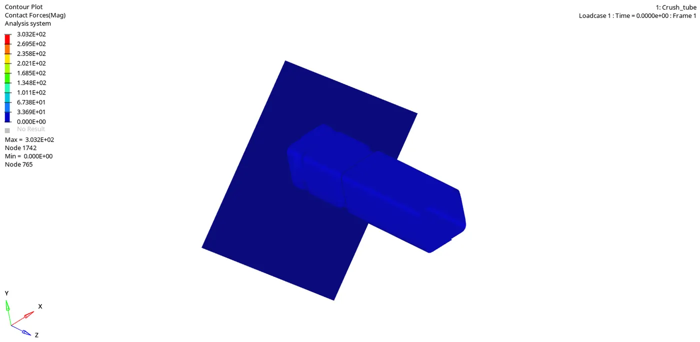
CONTACT FORCE SIMULATION:
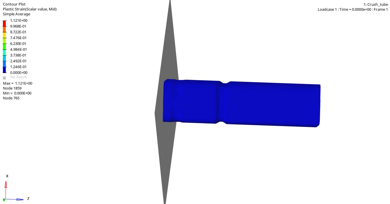
PLASTIC STRAIN SIMULATION:
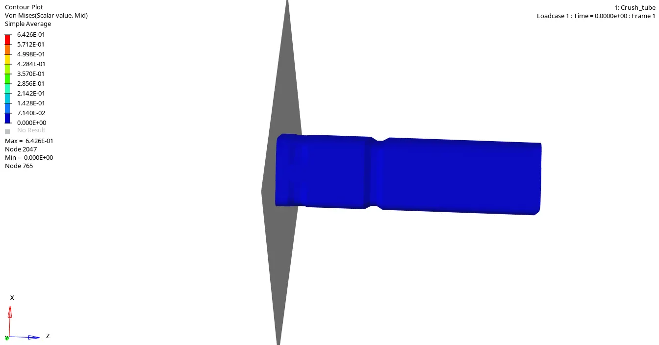
VONMISES SIMULATION:
NOW WE HAVE TO OPEN A "TO1" FILE IN "HYPERGRAPH" TO PLOT ALL THE ENERGIES AS SHOWN BELOW:
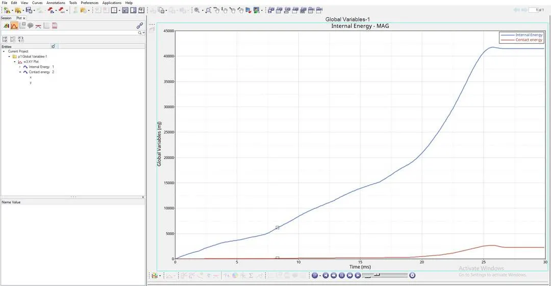
"INTERNAL ENERGY" AND "CONTACT ENERGY" PLOTS:
EXPLAINATION OF THE ABOVE ENERGY GRAPH:
- "INTERNAL ENERGY PLOT" : This Internal Energy or Strain Energy keeps on increasing due to the Increase in deformation of the "CRASH TUBE" untill the whole tube ruptures at a point, and after reaching this rupture point the Internal Energy is constant, this is because there will be a decrease in the Internal Energy, at this point elements stop absorbing energy, this is because plastic deformation has already happened, at this point all the elements would have experienced the "Ultimate plastic strain" and would have been deformed completely. This happens till it reaches "26.25th second".
- Here in the above graph, "INTERNAL ENERGY" is not increasing "LINEARLY", That is the graph of "INTERNAL ENERGY" is "NON-LINEAR", this is because "CRASH-TUBE" is made up of "4-SHELLS", among them "2-SHELLS" are of thickness "3mm" and the other "2-SHELLS" are of thickness "2mm".
- As per the above graph, "INTERNAL ENERGY" will be "CONSTANT" after "26.25th second".
- Here "MAXIMUM INTERNAL ENERGY" is above "41250 milli joule".
- "CONTACT ENERGY PLOT" : From "0th second" to "7.5th second" , "2-SHELLS" of "2mm" thick is in contact with "RIGID-BODY", But after This contact energy slightly increases after "7.5th second", at this point "2-SHELLS" of "3mm" thick is being compressed and drastically increases after "20th second", here contact force is high because at this point the whole "CRASH-TUBE" elements come in contact with the "RIGID-BODY", That means the whole component is being compressed totally, to crash this we need more force, so here the "CRASH-TUBE" needs more "CONTACT FORCE", hence experiences more "CONTACT ENERGY".
- Here at this point the whole component comes in contact with "RIGID BODY" and "SELF-CONTACT" of the "CRASH-TUBE" is happening here, so "CONTACT ENERGY INCREASES" at this point.
- After "26.25th second", "CONTACT ENERGY" is constant, At this point the whole "CRASH-TUBE" will be crushed completely and this completely crushed "CRASH-TUBE" will no longer be in contact with "RIGID-WALL", which means this completely crushed "CRASH-TUBE" will get detached from the "RIGID WALL", so there will be no "CONTACT ENERGY" experienced by "CRASH-TUBE" component for "3.75 seconds" as shown in the above graph.
- Here "MAXIMUM CONTACT ENERGY" is near to "2500 milli joule".
"RIGID WALL FORCES" PLOT:
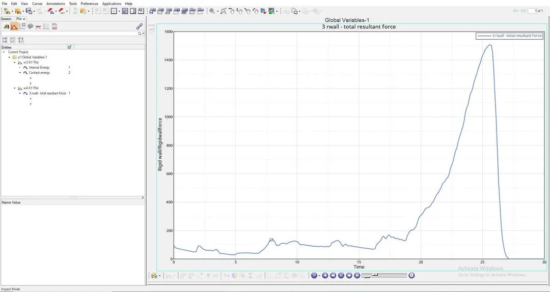
EXPLAINATION OF THE ABOVE RIGID WALL FORCE GRAPH:
- "RIGID-WALL FORCES PLOT" : This is the plot which shows the "IMPACT FORCE" experienced by the "RIGID-WALL", here "CRASH TUBE" is Impacting on the "RIGID-WALL".
- As per the above graph untill this "20th second", "RIGID BODY" will be experiencing forces from the "CRASH-TUBE"component, After this the "RIGID BODY" force will increase drastically, this is because at this stage "RIGID BODY" will experience more "CONTACT FORCE" from the "CRASH-TUBE", so to avoid this "CRASH TUBE" from penetrating into the "RIGID WALL", This "RIGID WALL" will induce maximum "RIGID WALL FORCES" to avoid "SLAVE NODES" from penetrating into the "MASTER NODE".
- After "26.25th second" the "RIGID WALL FORCES" will decrease and come to "0", this is because "CRASH-TUBE" will no longer be in contact after "26.25th second" as shown in the above graph.
- Here "MAXIMUM RIGID WALL FORCE" Reach to "1500KN".
CASE-3:
RUNNING THE GIVEN MODEL BY IMPORTING "Crash_tube_0000.rad" TO SOLVER DECK:
"MATERIAL CARDS" AND "PROPERTY CARD" WILL BE IN DEFAULT, SAME AS IN THE ABOVE CASE:
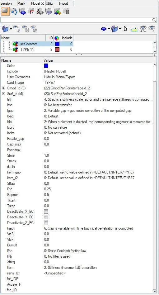
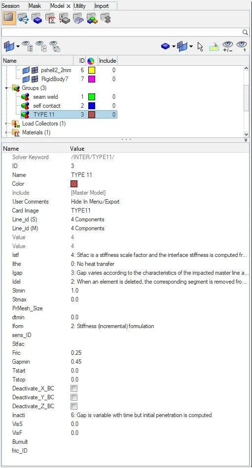
HERE WE KEEP THE CHANGED TYPE-7 "SELF CONTACT" CARD AND CREATE A NEW "INTERFACE CARD" WHICH WILL BE IN "TYPE-11" IN GROUPS TO THE "RECOMMENDED VALUES" AS SHOWN BELOW:
CARD NAME : "SELF CONTACT" AND CARD IMAGE : "TYPE-7":
CARD NAME : "TYPE-11" AND CARD IMAGE : "TYPE-11":
WE HAVE TO NOW START THE SIMULATION BY CLICKING ON TO "ANALYSIS" > "RADIOSS"
RESULTS OF CASE-3 :
ERRORS ARE AS SHOWN BELOW:
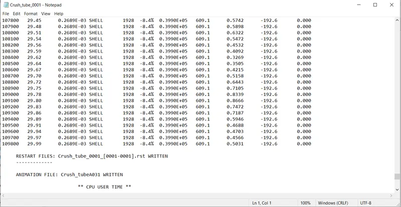
FROM THE ABOVE RESULT WE GET:
ENERGY ERROR =-8.4% (Here the energy error is in permissible range, so we can move forward)
MASS ERROR = 0
NUMBER OF CYCLES = 109829
TOTAL ELAPSED TIME = 418.40 sec
WE HAVE TO OPEN "h3d" FILE IN HYPERVIEW TO SEE THE ANIMATIONS AS SHOWN BELOW:
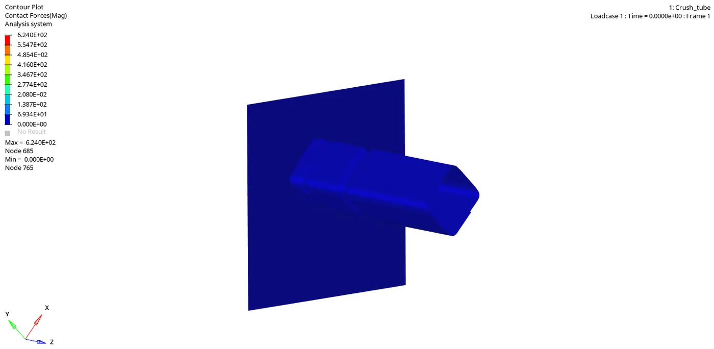
CONTACT FORCE SIMULATION:
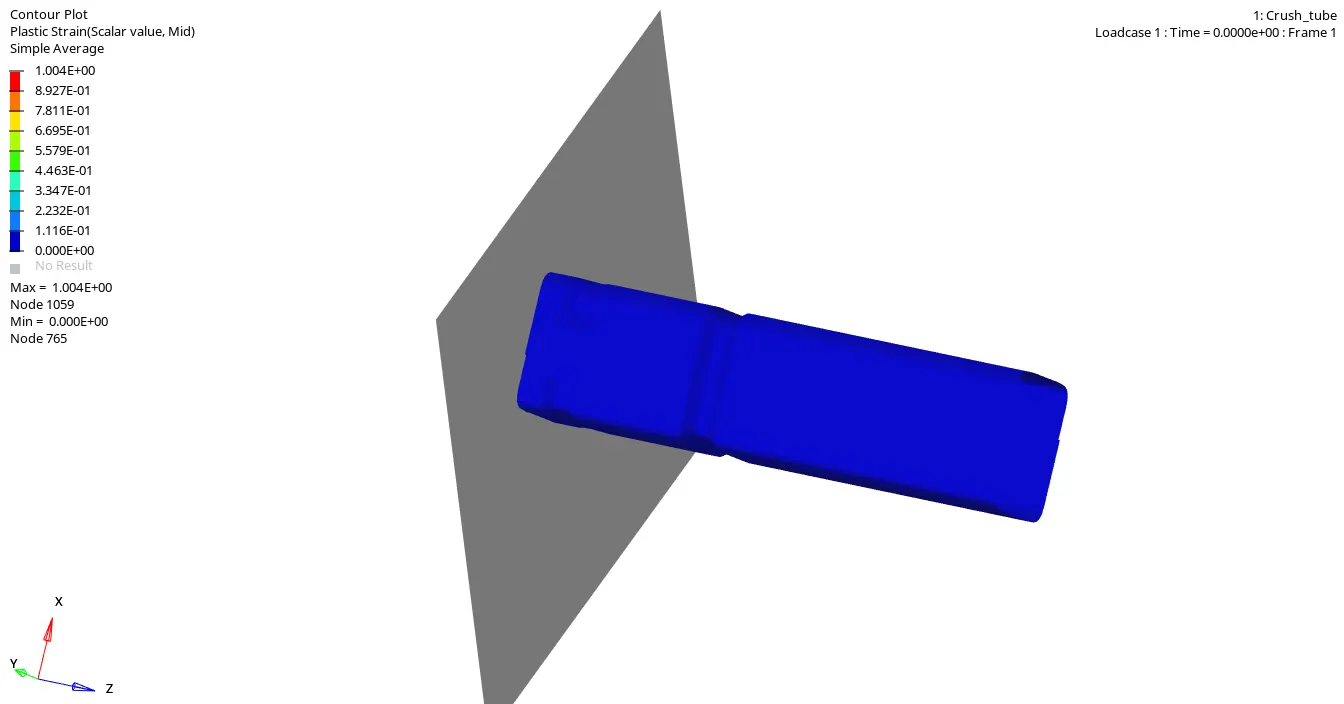
PLASTIC STRAIN SIMULATION:
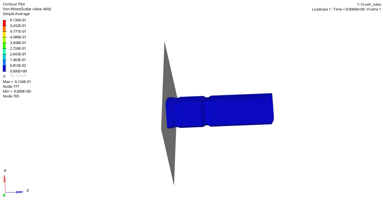
VONMISES SIMULATION:
NOW WE HAVE TO OPEN A "TO1" FILE IN "HYPERGRAPH" TO PLOT ALL THE ENERGIES AS SHOWN BELOW:
"INTERNAL ENERGY" AND "CONTACT ENERGY" PLOTS:
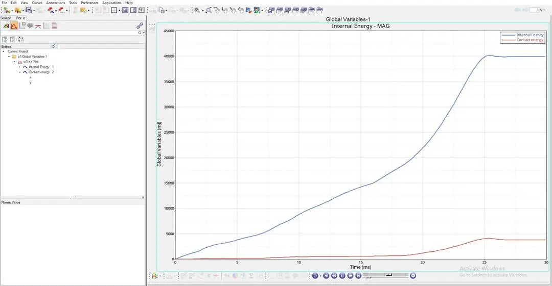
EXPLAINATION OF THE ABOVE ENERGY GRAPH:
- "INTERNAL ENERGY PLOT" : This Internal Energy or Strain Energy keeps on increasing due to the Increase in deformation of the "CRASH TUBE" untill the whole tube ruptures at a point, and after reaching this rupture point the Internal Energy is constant, this is because there will be a decrease in the Internal Energy, at this point elements stop absorbing energy, this is because plastic deformation has already happened, at this point all the elements would have experienced the "Ultimate plastic strain" and would have been deformed completely. This happens till it reaches "26th second".
- Here in the above graph, "INTERNAL ENERGY" is not increasing "LINEARLY", That is the graph of "INTERNAL ENERGY" is "NON-LINEAR", this is because "CRASH-TUBE" is made up of "4-SHELLS", among them "2-SHELLS" are of thickness "3mm" and the other "2-SHELLS" are of thickness "2mm".
- As per the above graph, "INTERNAL ENERGY" will be "CONSTANT" after "26th second".
- Here "MAXIMUM INTERNAL ENERGY" is "40000 milli joule".
- "CONTACT ENERGY PLOT" : From "0th second" to "7.5th second" , "2-SHELLS" of "2mm" thick is in contact with "RIGID-BODY" and the "CONTACT ENERGY" is slightly more when compared to previous cases, But after This contact energy slightly increases even more after "7.5th second", at this point "2-SHELLS" of "3mm" thick is being compressed and drastically increases after "20th second", here contact force is high because at this point the whole "CRASH-TUBE" elements come in contact with the "RIGID-BODY", That means the whole component is being compressed totally, to crash this we need more force, so here the "CRASH-TUBE" needs more "CONTACT FORCE", hence experiences more "CONTACT ENERGY".
- Here at this point the whole component comes in contact with "RIGID BODY" and "SELF-CONTACT" of the "CRASH-TUBE" is happening here, so "CONTACT ENERGY INCREASES" at this point.
- After "26th second", "CONTACT ENERGY" is constant, At this point the whole "CRASH-TUBE" will be crushed completely and this completely crushed "CRASH-TUBE" will no longer be in contact with "RIGID-WALL", which means this completely crushed "CRASH-TUBE" will get detached from the "RIGID WALL", so there will be no "CONTACT ENERGY" experienced by "CRASH-TUBE" component for "4 seconds" as shown in the above graph.
- Here "MAXIMUM CONTACT ENERGY" is above "3750 milli joule".
"RIGID WALL FORCES" PLOT:
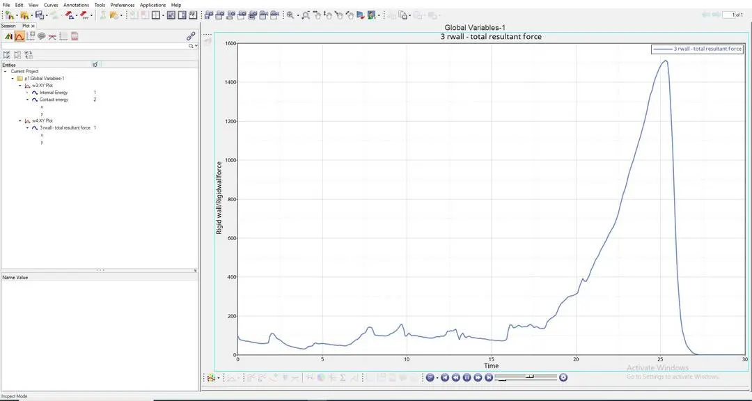
EXPLAINATION OF THE ABOVE RIGID WALL FORCE GRAPH:
- "RIGID-WALL FORCES PLOT" : This is the plot which shows the "IMPACT FORCE" experienced by the "RIGID-WALL", here "CRASH TUBE" is Impacting on the "RIGID-WALL".
- As per the above graph untill this "20th second", "RIGID BODY" will be experiencing forces from the "CRASH-TUBE"component, After this the "RIGID BODY" force will increase drastically, this is because at this stage "RIGID BODY" will experience more "CONTACT FORCE" from the "CRASH-TUBE", so to avoid this "CRASH TUBE" from penetrating into the "RIGID WALL", This "RIGID WALL" will induce maximum "RIGID WALL FORCES" to avoid "SLAVE NODES" from penetrating into the "MASTER NODE".
- After "26th second" the "RIGID WALL FORCES" will decrease and come to "0", this is because "CRASH-TUBE" will no longer be in contact after "26th second" as shown in the above graph.
- Here "MAXIMUM RIGID WALL FORCE" Reach above "1500KN".
CASE-4:
RUNNING THE GIVEN MODEL BY IMPORTING "Crash_tube_0000.rad" TO SOLVER DECK:
"MATERIAL CARDS" AND "PROPERTY CARD" WILL BE IN DEFAULT, SAME AS IN THE ABOVE CASE:
HERE WE KEEP THE CHANGED "TYPE-7" "SELF CONTACT" CARD AND WE KEEP THE "TYPE-11" INTERFACE CARD WHICH WILL BE IN THE NAME "TYPE-11" IN GROUPS TO THE "RECOMMENDED VALUES" AS ABOVE IN THE 3RD CASE:
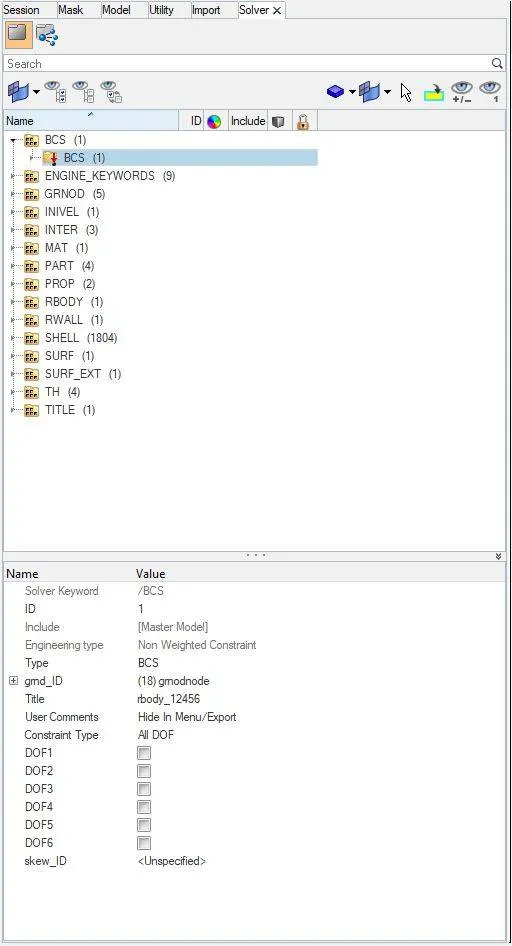
HERE WE WILL REMOVE ALL THE BOUNDARY CONDITION ON RIGID BODY NODE, THIS IS DONE IN "SOLVER BROWSER", IN THAT WE HAVE TO GOTO "BCS" WHICH MEANS "BOUNDARY CONDITIIONS" AS SHOWN BELOW:
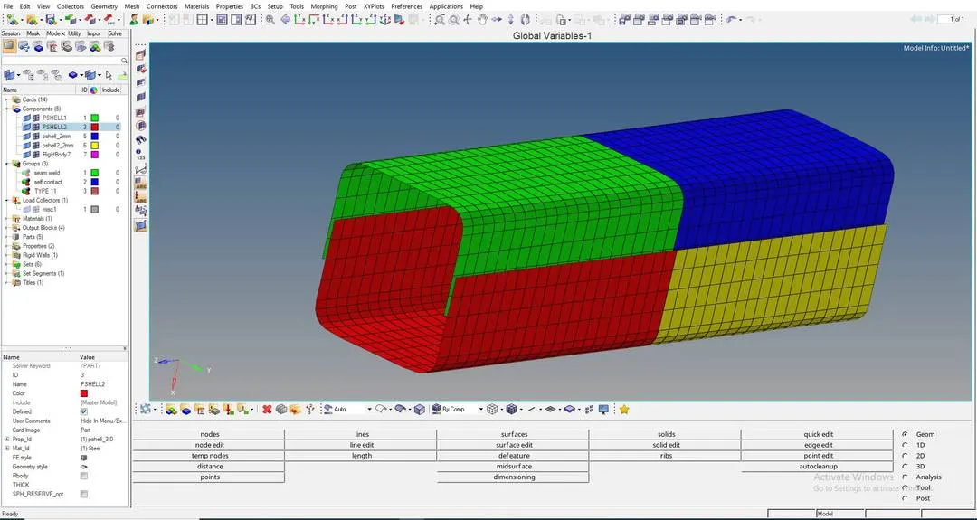
HERE AS PER THIS CASE WE HAVE TO REMOVE BOTH THE NOTCHES FROM THIS "CRASH TUBE" MODEL BY GOING TO: "QUICK EDIT" > "NODE EDIT" > "NODE ALLIGNMENT"
BY USING THIS TOOL WE CAN REMOVE NOTCHES FROM THE MODEL AS SHOWN BELOW:
IMAGE-1:
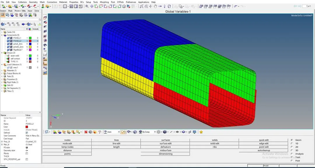
IMAGE-2:
WE HAVE TO NOW START THE SIMULATION BY CLICKING ON TO "ANALYSIS" > "RADIOSS"
RESULTS OF CASE-4 :
ERRORS ARE AS SHOWN BELOW:
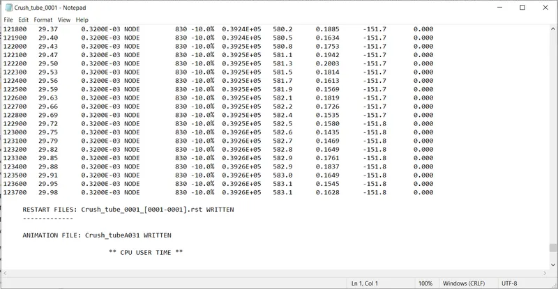
FROM THE ABOVE RESULT WE GET:
ENERGY ERROR =-10.0% (Here the energy error is in permissible range, so we can move forward)
MASS ERROR = 0
NUMBER OF CYCLES = 123772
TOTAL ELAPSED TIME = 442.00 sec
WE HAVE TO OPEN "h3d" FILE IN HYPERVIEW TO SEE THE ANIMATIONS AS SHOWN BELOW:
CONTACT FORCE SIMULATION:
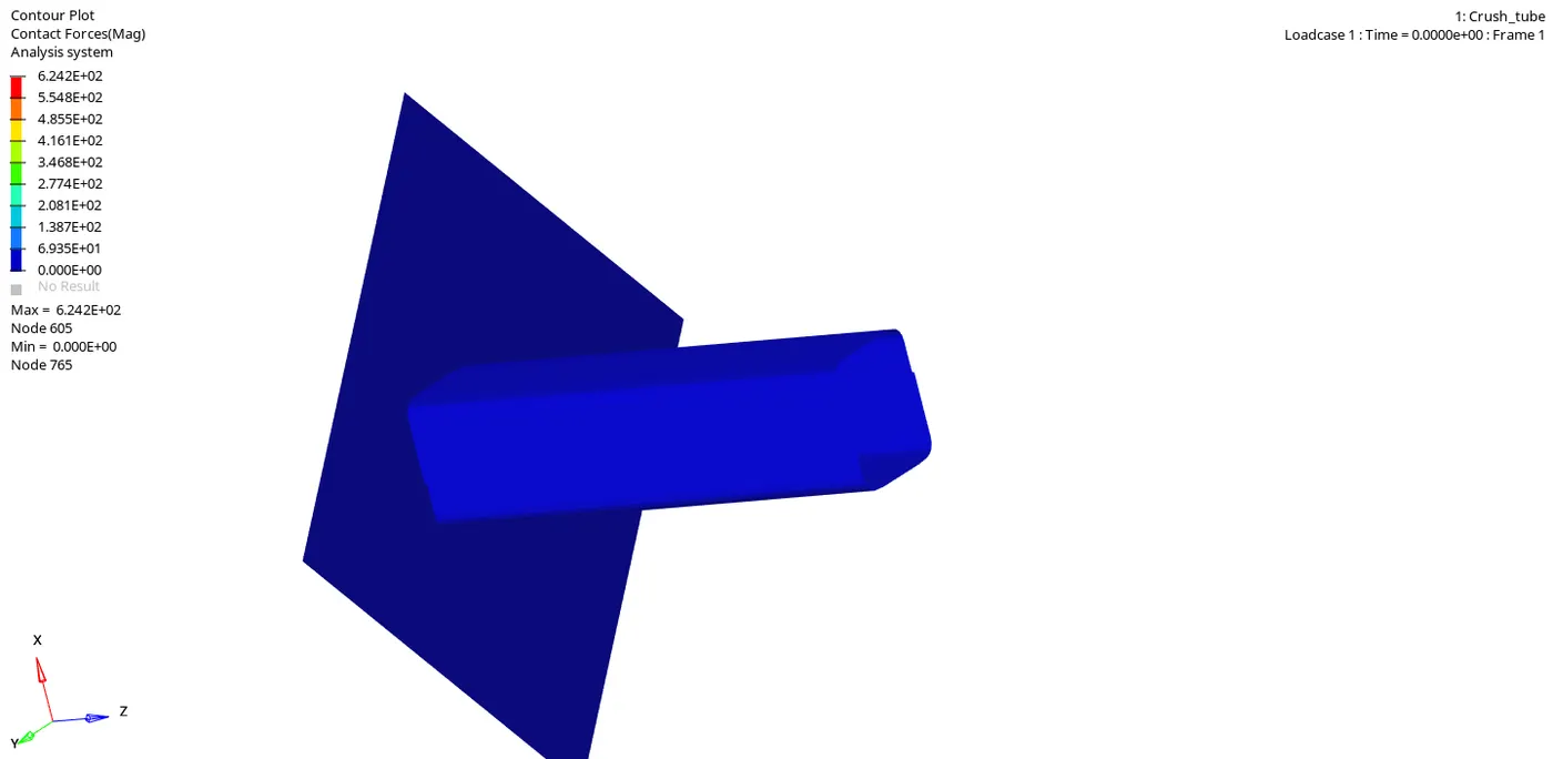
PLASTIC STRAIN SIMULATION:
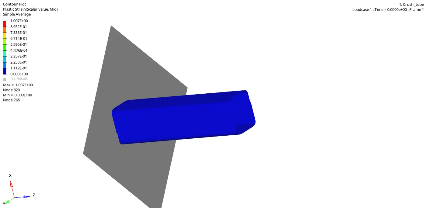
VONMISES SIMULATION:
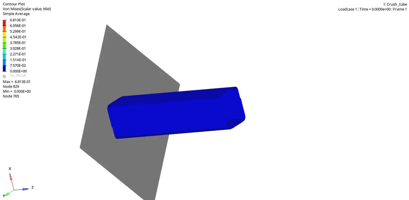
NOW WE HAVE TO OPEN A "TO1" FILE IN "HYPERGRAPH" TO PLOT ALL THE ENERGIES AS SHOWN BELOW:
"INTERNAL ENERGY" AND "CONTACT ENERGY" PLOTS:
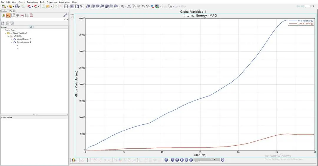
EXPLAINATION OF THE ABOVE ENERGY GRAPH:
- "INTERNAL ENERGY PLOT" : This Internal Energy or Strain Energy keeps on increasing due to the Increase in deformation of the "CRASH TUBE" untill the whole tube ruptures at a point, and after reaching this rupture point the Internal Energy is constant, this is because there will be a decrease in the Internal Energy, at this point elements stop absorbing energy, this is because plastic deformation has already happened, at this point all the elements would have experienced the "Ultimate plastic strain" and would have been deformed completely. This happens till it reaches "27.5th second".
- Here in the above graph, "INTERNAL ENERGY" is not increasing "LINEARLY", That is the graph of "INTERNAL ENERGY" is "NON-LINEAR", this is because "CRASH-TUBE" is made up of "4-SHELLS", among them "2-SHELLS" are of thickness "3mm" and the other "2-SHELLS" are of thickness "2mm".
- As per the above graph, "INTERNAL ENERGY" will be "CONSTANT" after "27.5th second".
- Here "MAXIMUM INTERNAL ENERGY" is below "40000 milli joule".
- "CONTACT ENERGY PLOT" : From "0th second" to "7.5th second" , "2-SHELLS" of "2mm" thick is in contact with "RIGID-BODY", and the "CONTACT ENERGY" starts increasing at "2.5th second" and is more when compared to previous cases, But after This contact energy slightly increases even more after "7.5th second", at this point "2-SHELLS" of "3mm" thick is being compressed and drastically increases after "20th second", here contact force is high because at this point the whole "CRASH-TUBE" elements come in contact with the "RIGID-BODY", That means the whole component is being compressed totally, to crash this we need more force, so here the "CRASH-TUBE" needs more "CONTACT FORCE", hence experiences more "CONTACT ENERGY".
- Here at this point the whole component comes in contact with "RIGID BODY" and "SELF-CONTACT" of the "CRASH-TUBE" is happening here, so "CONTACT ENERGY INCREASES" at this point.
- After "27.5th second", "CONTACT ENERGY" is constant, At this point the whole "CRASH-TUBE" will be crushed completely and this completely crushed "CRASH-TUBE" will no longer be in contact with "RIGID-WALL", which means this completely crushed "CRASH-TUBE" will get detached from the "RIGID WALL", so there will be no "CONTACT ENERGY" experienced by "CRASH-TUBE" component for "2.5 seconds" as shown in the above graph.
- Here "MAXIMUM CONTACT ENERGY" is slightly below "5000 milli joule".
"RIGID WALL FORCES" PLOT:
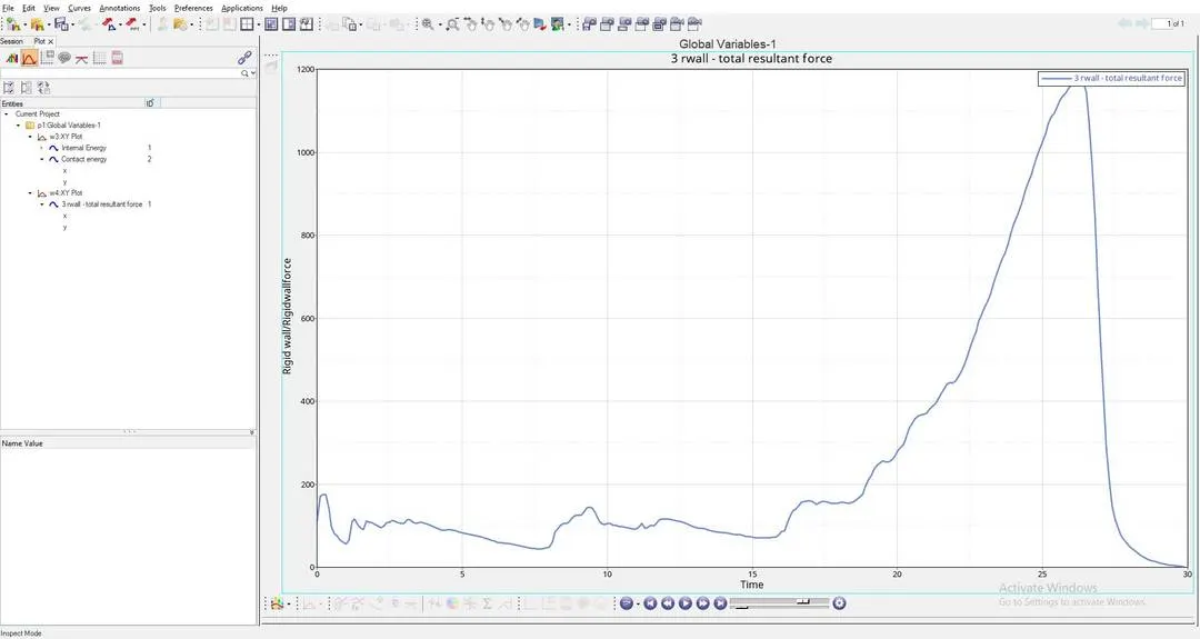
EXPLAINATION OF THE ABOVE RIGID WALL FORCE GRAPH:
- "RIGID-WALL FORCES PLOT" : This is the plot which shows the "IMPACT FORCE" experienced by the "RIGID-WALL", here "CRASH TUBE" is Impacting on the "RIGID-WALL".
- As per the above graph untill this "20th second", "RIGID BODY" will be experiencing forces from the "CRASH-TUBE"component, After this the "RIGID BODY" force will increase drastically, this is because at this stage "RIGID BODY" will experience more "CONTACT FORCE" from the "CRASH-TUBE", so to avoid this "CRASH TUBE" from penetrating into the "RIGID WALL", This "RIGID WALL" will induce maximum "RIGID WALL FORCES" to avoid "SLAVE NODES" from penetrating into the "MASTER NODE".
- After reaching "27.5th second" the "RIGID WALL FORCES" will decrease and come to "0", this is because "CRASH-TUBE" will no longer be in contact after "27.5th second" as shown in the above graph.
- Here "MAXIMUM RIGID WALL FORCE" Reach above "1190KN".
CASE-5:
RUNNING THE GIVEN MODEL BY IMPORTING "Crash_tube_0000.rad" TO SOLVER DECK:
"MATERIAL CARDS" AND "PROPERTY CARD" WILL BE IN DEFAULT, SAME AS IN THE ABOVE CASE:
HERE WE KEEP THE CHANGED "TYPE-7" "SELF CONTACT" CARD AND WE KEEP THE "TYPE-11" INTERFACE CARD WHICH WILL BE IN THE NAME "TYPE-11" IN GROUPS TO THE "RECOMMENDED VALUES" AS ABOVE IN THE 3RD CASE:
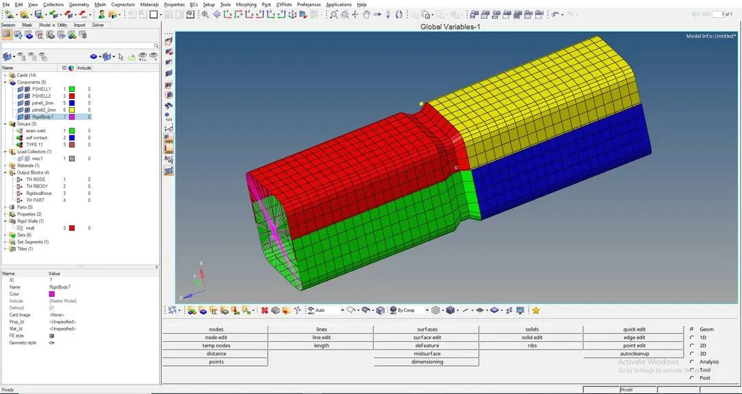
HERE WE HAVE TO CREATE A "NEW NOTCH" IN THE "MIDDLE", TO DO THIS WE HAVE TO GOTO: "TOOLS" > "TRANSLATE"
WITH THE HELP OF THIS "TRANSLATE" TOOL WE CAN MAKE A NOTCH IN THE MIDDLE OF THE "CRASH TUBE" MODEL USING THE CASE-4 MODEL AS SHOWN BELOW:
IMAGE-1:
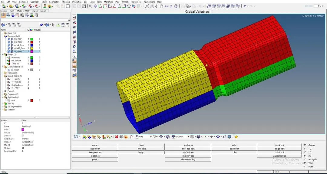
IMAGE-2:
WE HAVE TO NOW START THE SIMULATION BY CLICKING ON TO "ANALYSIS" > "RADIOSS"
RESULTS OF CASE-5 :
ERRORS ARE AS SHOWN BELOW:
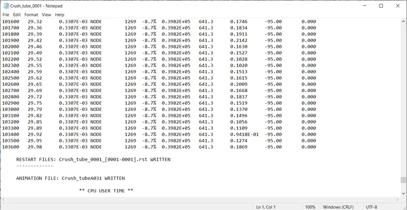
FROM THE ABOVE RESULT WE GET:
ENERGY ERROR =-8.7% (Here the energy error is in permissible range, so we can move forward)
MASS ERROR = 0
NUMBER OF CYCLES = 103647
TOTAL ELAPSED TIME = 374.18 sec
WE HAVE TO OPEN "h3d" FILE IN HYPERVIEW TO SEE THE ANIMATIONS AS SHOWN BELOW:
CONTACT FORCE SIMULATION:
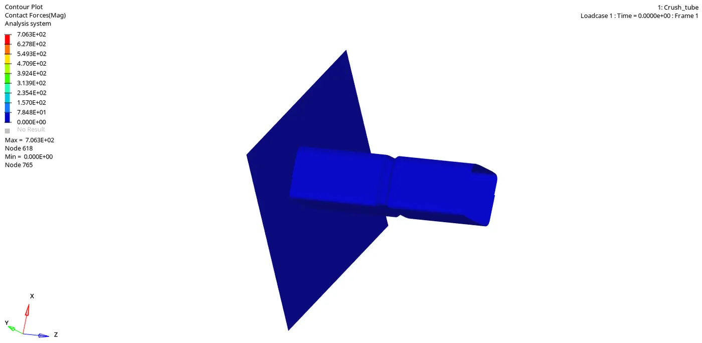
PLASTIC STRAIN SIMULATION:
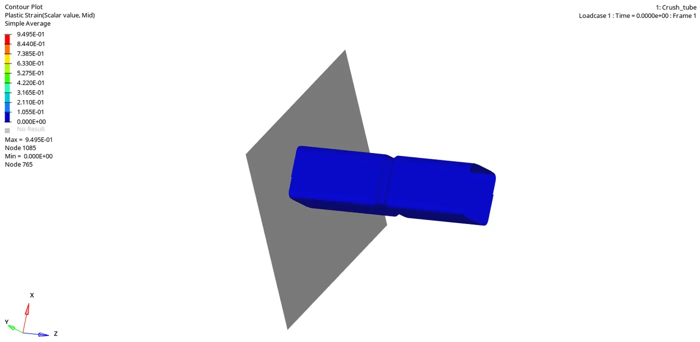
VONMISES SIMULATION:
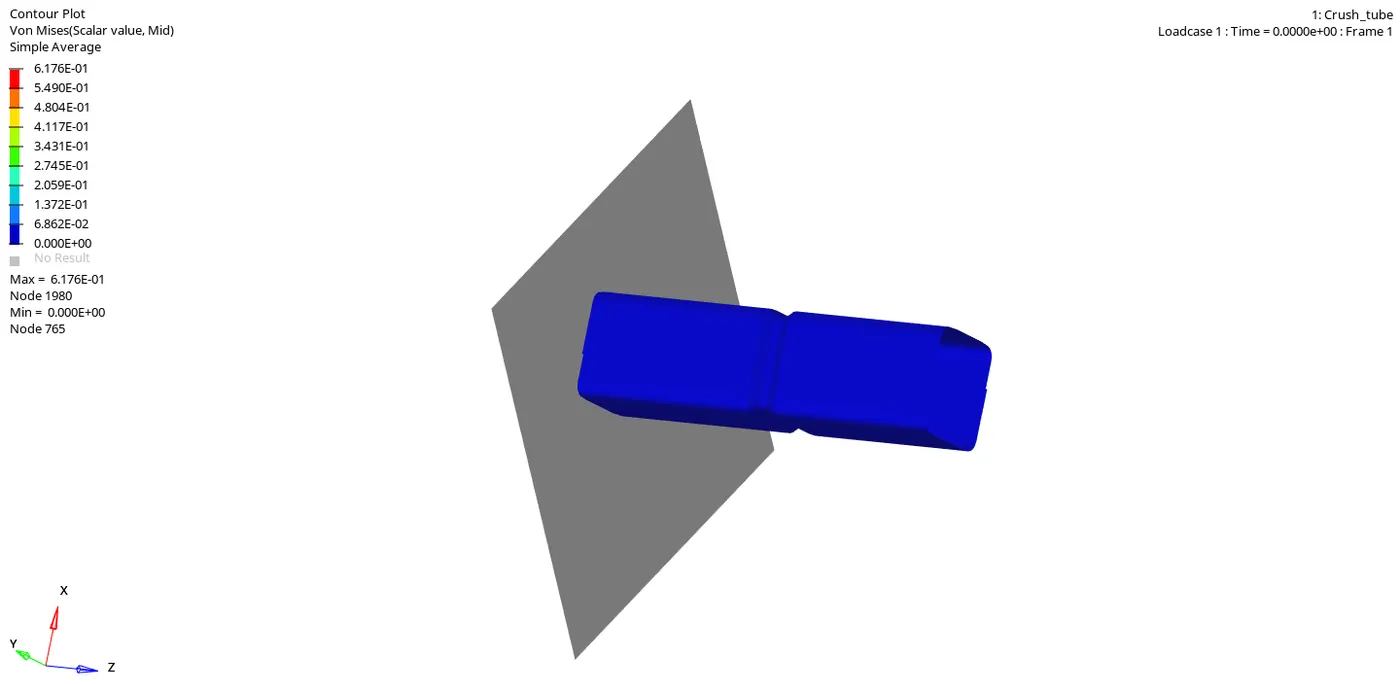
NOW WE HAVE TO OPEN A "TO1" FILE IN "HYPERGRAPH" TO PLOT ALL THE ENERGIES AS SHOWN BELOW:
"INTERNAL ENERGY" AND "CONTACT ENERGY" PLOTS:
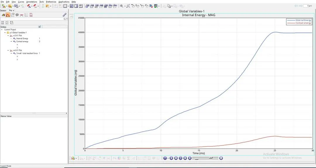
EXPLAINATION OF THE ABOVE ENERGY GRAPH:
- "INTERNAL ENERGY PLOT" : This Internal Energy or Strain Energy keeps on increasing due to the Increase in deformation of the "CRASH TUBE" untill the whole tube ruptures at a point, and after reaching this rupture point the Internal Energy is constant, this is because there will be a decrease in the Internal Energy, at this point elements stop absorbing energy, this is because plastic deformation has already happened, at this point all the elements would have experienced the "Ultimate plastic strain" and would have been deformed completely. This happens till it reaches "25th second".
- Here in the above graph, "INTERNAL ENERGY" is not increasing "LINEARLY", That is the graph of "INTERNAL ENERGY" is "NON-LINEAR", this is because "CRASH-TUBE" is made up of "4-SHELLS", among them "2-SHELLS" are of thickness "3mm" and the other "2-SHELLS" are of thickness "2mm".
- As per the above graph, "INTERNAL ENERGY" will be "CONSTANT" after "25th second".
- Here "MAXIMUM INTERNAL ENERGY" is at "40000 milli joule".
- "CONTACT ENERGY PLOT" : From "0th second" to "7.5th second" ,"2-SHELLS" of "2mm" thick is in contact with "RIGID-BODY", But after This contact energy slightly increases after "7.5th second", at this point "2-SHELLS" of "3mm" thick is being compressed and drastically increases after "20th second", here contact force is high because at this point the whole "CRASH-TUBE" elements come in contact with the "RIGID-BODY", That means the whole component is being compressed totally, to crash this we need more force, so here the "CRASH-TUBE" needs more "CONTACT FORCE", hence experiences more "CONTACT ENERGY".
- Here at this point the whole component comes in contact with "RIGID BODY" and "SELF-CONTACT" of the "CRASH-TUBE" is happening here, so "CONTACT ENERGY INCREASES" at this point.
- After "25th second", "CONTACT ENERGY" is constant, At this point the whole "CRASH-TUBE" will be crushed completely and this completely crushed "CRASH-TUBE" will no longer be in contact with "RIGID-WALL", which means this completely crushed "CRASH-TUBE" will get detached from the "RIGID WALL", so there will be no "CONTACT ENERGY" experienced by "CRASH-TUBE" component for "5 seconds" as shown in the above graph.
- Here "MAXIMUM CONTACT ENERGY" is above "4000 milli joule".
"RIGID WALL FORCES" PLOT:
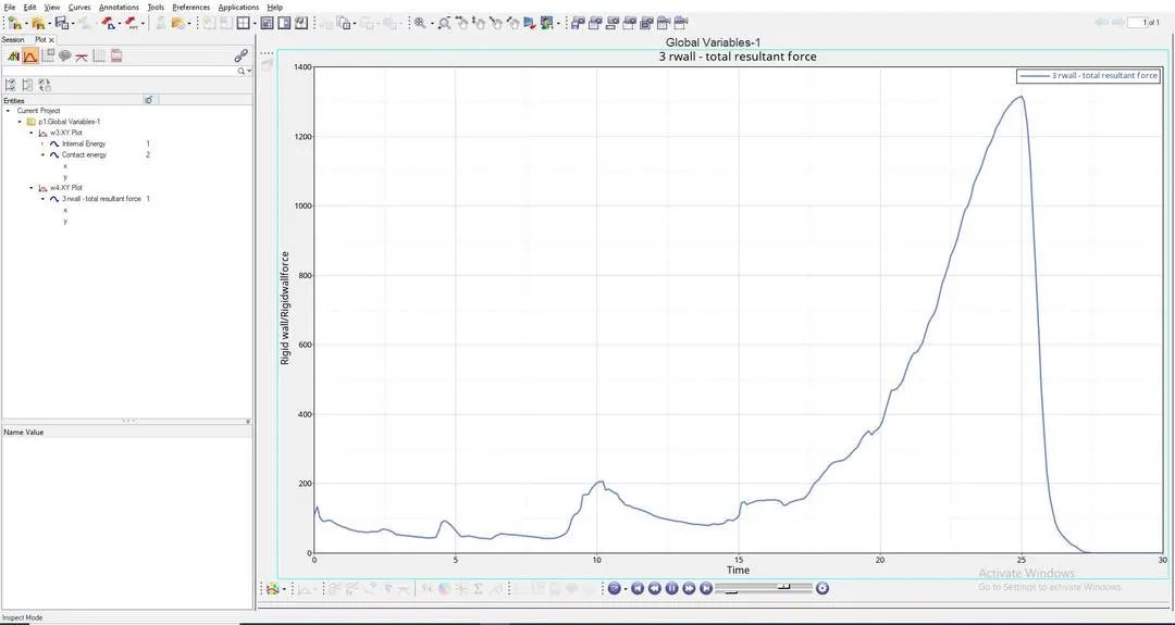
EXPLAINATION OF THE ABOVE RIGID WALL FORCE GRAPH:
- "RIGID-WALL FORCES PLOT" : This is the plot which shows the "IMPACT FORCE" experienced by the "RIGID-WALL", here "CRASH TUBE" is Impacting on the "RIGID-WALL".
- As per the above graph untill this "20th second", "RIGID BODY" will be experiencing forces from the "CRASH-TUBE"component, After this the "RIGID BODY" force will increase drastically, this is because at this stage "RIGID BODY" will experience more "CONTACT FORCE" from the "CRASH-TUBE", so to avoid this "CRASH TUBE" from penetrating into the "RIGID WALL", This "RIGID WALL" will induce maximum "RIGID WALL FORCES" to avoid "SLAVE NODES" from penetrating into the "MASTER NODE".
- After reaching "25th second " the "RIGID WALL FORCES" will decrease and come to "0", this is because "CRASH-TUBE" will no longer be in contact after "25th second" as shown in the above graph.
- Here "MAXIMUM RIGID WALL FORCE" Reach above "1300KN".
CASE-6:
RUNNING THE GIVEN MODEL BY IMPORTING "Crash_tube_0000.rad" TO SOLVER DECK:
"MATERIAL CARDS" AND "PROPERTY CARD" WILL BE IN DEFAULT, SAME AS IN THE ABOVE CASE:
HERE WE KEEP THE CHANGED "TYPE-7" "SELF CONTACT" CARD AND WE KEEP THE "TYPE-11" INTERFACE CARD WHICH WILL BE IN THE NAME "TYPE-11" IN GROUPS TO THE "RECOMMENDED VALUES" AS ABOVE IN THE 3RD CASE:
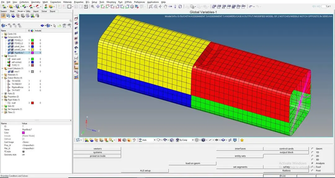
HERE WE HAVE TO CREATE A "NEW NOTCH" WITH NODES ONLY FROM OPPOSING 2 FACES, TO DO THIS WE HAVE TO GOTO: "TOOLS" > "TRANSLATE"
WITH THE HELP OF THIS "TRANSLATE" TOOL WE CAN MAKE A NOTCH IN THE MIDDLE OF THE "CRASH TUBE" MODEL USING THE CASE-4 MODEL AS SHOWN BELOW:
IMAGE-1:
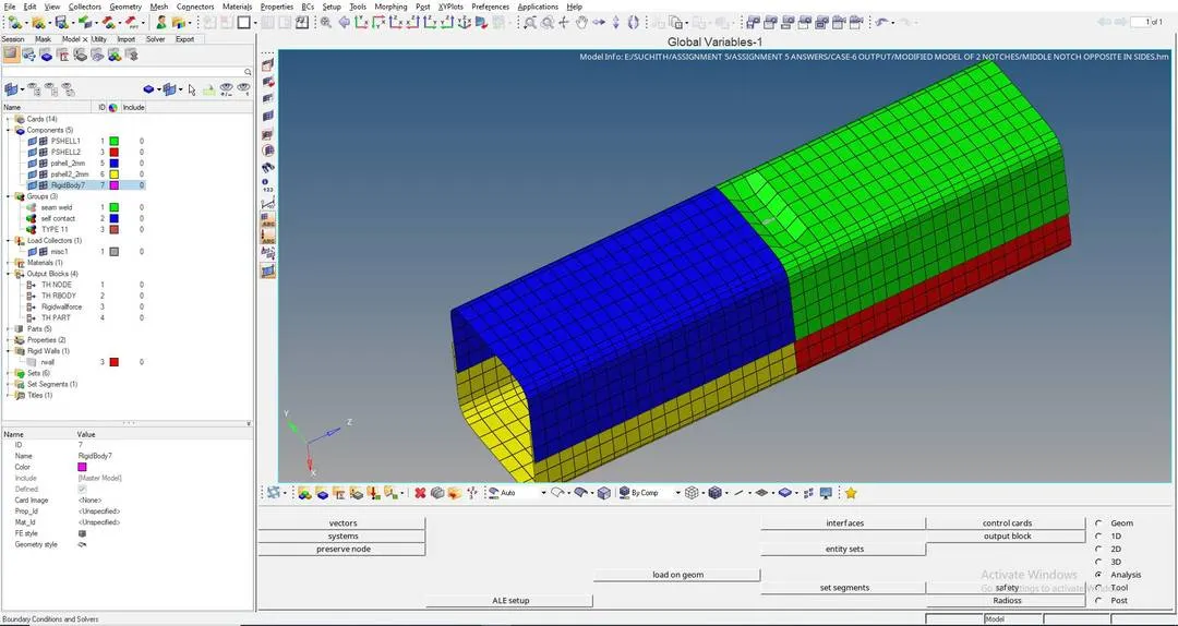
IMAGE-2:
WE HAVE TO NOW START THE SIMULATION BY CLICKING ON TO "ANALYSIS" > "RADIOSS"
RESULTS OF CASE-6 :
ERRORS ARE AS SHOWN BELOW:
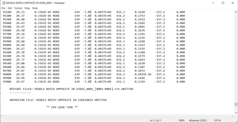
FROM THE ABOVE RESULT WE GET:
ENERGY ERROR =-7.8% (Here the energy error is in permissible range, so we can move forward)
MASS ERROR = 0
NUMBER OF CYCLES = 97082
TOTAL ELAPSED TIME = 357.79 sec
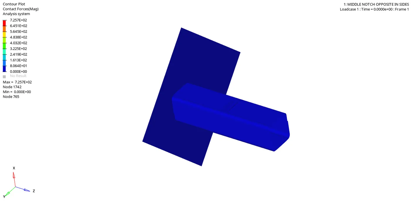
WE HAVE TO OPEN "h3d" FILE IN HYPERVIEW TO SEE THE ANIMATIONS AS SHOWN BELOW:
CONTACT FORCE SIMULATION:
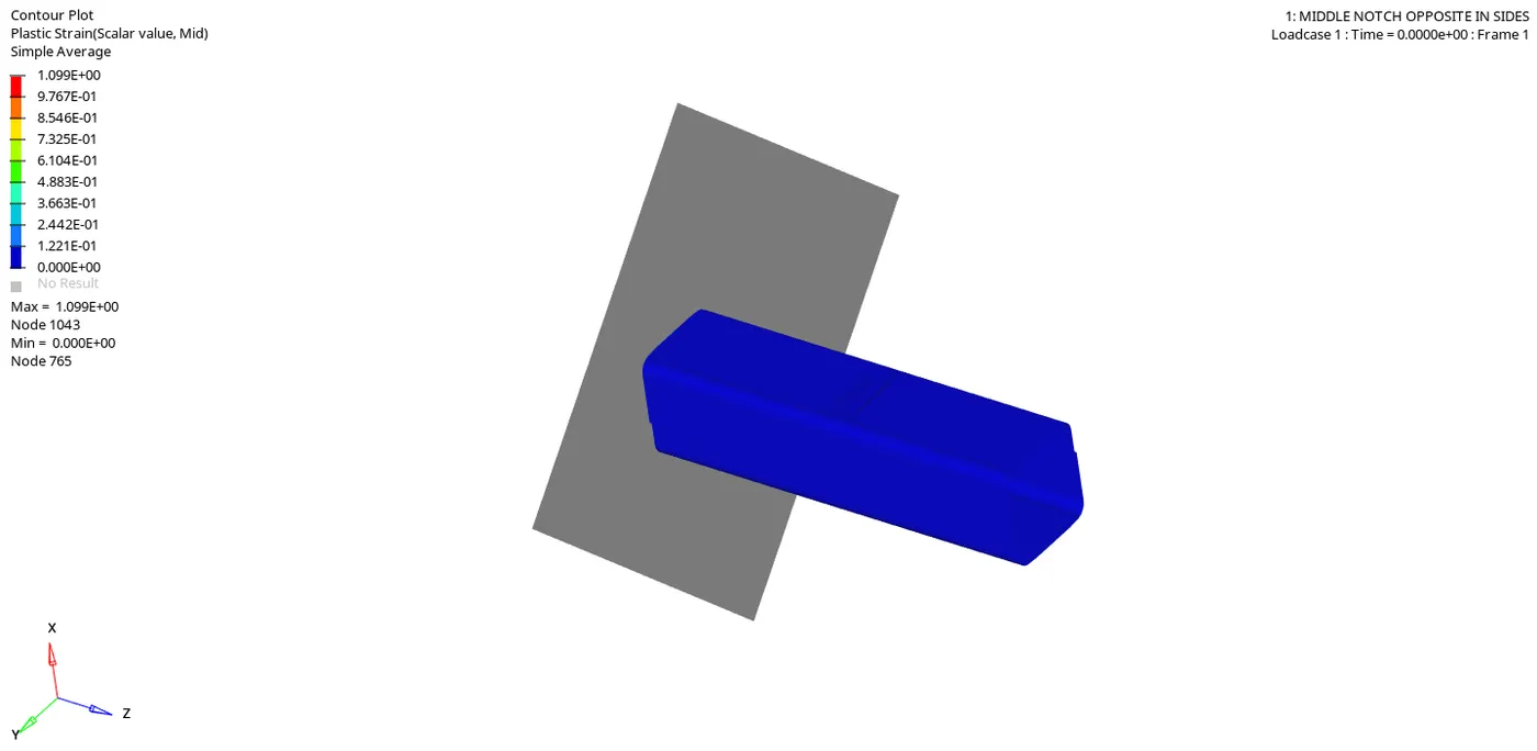
PLASTIC STRAIN SIMULATION:
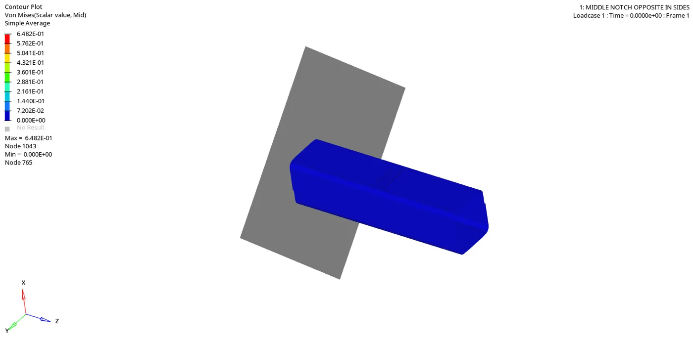
VONMISES SIMULATION:
NOW WE HAVE TO OPEN A "TO1" FILE IN "HYPERGRAPH" TO PLOT ALL THE ENERGIES AS SHOWN BELOW:
"INTERNAL ENERGY" AND "CONTACT ENERGY" PLOTS:
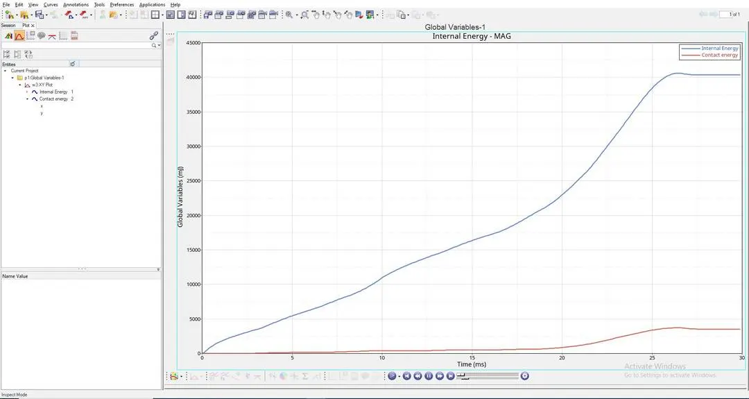
EXPLAINATION OF THE ABOVE ENERGY GRAPH:
- "INTERNAL ENERGY PLOT" : This Internal Energy or Strain Energy keeps on increasing due to the Increase in deformation of the "CRASH TUBE" untill the whole tube ruptures at a point, and after reaching this rupture point the Internal Energy is constant, this is because there will be a decrease in the Internal Energy, at this point elements stop absorbing energy, this is because plastic deformation has already happened, at this point all the elements would have experienced the "Ultimate plastic strain" and would have been deformed completely. This happens till it reaches "27th second".
- Here in the above graph, "INTERNAL ENERGY" is not increasing "LINEARLY", That is the graph of "INTERNAL ENERGY" is "NON-LINEAR", this is because "CRASH-TUBE" is made up of "4-SHELLS", among them "2-SHELLS" are of thickness "3mm" and the other "2-SHELLS" are of thickness "2mm".
- As per the above graph, "INTERNAL ENERGY" will be "CONSTANT" after "27th second".
- Here "MAXIMUM INTERNAL ENERGY" is above "40000 milli joule".
- "CONTACT ENERGY PLOT" : From "0th second" to "7.5th second" , "2-SHELLS" of "2mm" thick is in contact with "RIGID-BODY", But after This contact energy slightly increases after "7.5th second", at this point "2-SHELLS" of "3mm" thick is being compressed and drastically increases after "20th second", here contact force is high because at this point the whole "CRASH-TUBE" elements come in contact with the "RIGID-BODY", That means the whole component is being compressed totally, to crash this we need more force, so here the "CRASH-TUBE" needs more "CONTACT FORCE", hence experiences more "CONTACT ENERGY".
- Here at this point the whole component comes in contact with "RIGID BODY" and "SELF-CONTACT" of the "CRASH-TUBE" is happening here, so "CONTACT ENERGY INCREASES" at this point.
- After "27th second", "CONTACT ENERGY" is constant, At this point the whole "CRASH-TUBE" will be crushed completely and this completely crushed "CRASH-TUBE" will no longer be in contact with "RIGID-WALL", which means this completely crushed "CRASH-TUBE" will get detached from the "RIGID WALL", so there will be no "CONTACT ENERGY" experienced by "CRASH-TUBE" component for "3 seconds" as shown in the above graph.
- Here "MAXIMUM CONTACT ENERGY" is near to "3750 milli joule".
"RIGID WALL FORCES" PLOT:
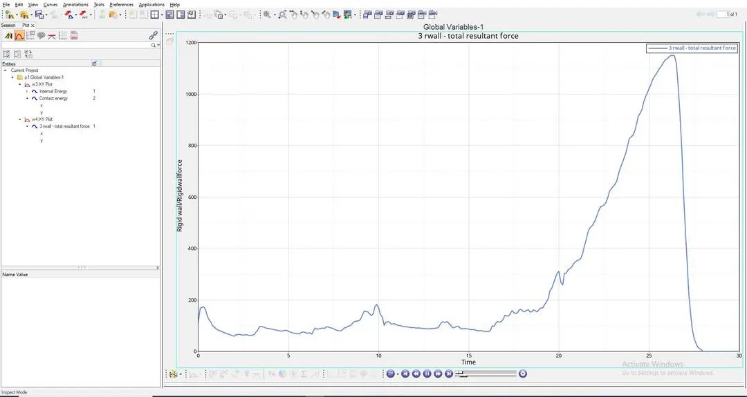
EXPLAINATION OF THE ABOVE RIGID WALL FORCE GRAPH:
- "RIGID-WALL FORCES PLOT" : This is the plot which shows the "IMPACT FORCE" experienced by the "RIGID-WALL", here "CRASH TUBE" is Impacting on the "RIGID-WALL".
- As per the above graph untill this "20th second", "RIGID BODY" will be experiencing forces from the "CRASH-TUBE"component, After this the "RIGID BODY" force will increase drastically, this is because at this stage "RIGID BODY" will experience more "CONTACT FORCE" from the "CRASH-TUBE", so to avoid this "CRASH TUBE" from penetrating into the "RIGID WALL", This "RIGID WALL" will induce maximum "RIGID WALL FORCES" to avoid "SLAVE NODES" from penetrating into the "MASTER NODE".
- After reaching "27th second " the "RIGID WALL FORCES" will decrease and come to "0", this is because "CRASH-TUBE" will no longer be in contact after "27th second" as shown in the above graph.
- Here "MAXIMUM RIGID WALL FORCE" Reach above "1150KN".
CONCLUSION:
- When we compare the results of both "CASE-1" and "CASE-2" with "TYPE-7" contact, the results are almost simillar, but in "CASE-2" we do it with all the recommende values, so we see there is an increase in both "CONTACT ENERGY" AND "RIGID WALL FORCES".
- We use "TYPE-11" contact, here we use "EDGE TO EDGE" contact with "NODE TO SURFACE" contact with "TYPE-7", so there will be more contact, that is why "CONTACT ENERGY" AND "RIGID WALL FORCES" is very high in "CASE-3" when compared to "CASE-1 AND CASE-2".
- We remove each and every notch in "CASE-4", and we are also removing boundary conditions, So here "RIGID WALL FORCES" decreases and "INTERNAL ENERGY" also decreases, but "CONTACT ENERGY" is too high, because of the removal of the boundary conditions.
- We prepare a notch in the middle of the component in"CASE-5", here we observe increase in "INTERNAL ENERGY" and "RIGID WALL FORCES", but "CONTACT ENERGY" decreases as compared to "CASE-4".
- We prepare 2 opposing notches on the componenet in "CASE-6", here we observe increase in "INTERNAL ENERGY", but decrease in "RIGID WALL FORCES" and "CONTACT ENERGY" as compared to "CASE-5".
- So the "CASE-6" has better results than the other cases compared above.