Assignment 5
Aim and Objective
- To create mesh for bumper assembly with mesh size = 6mm
- To run the crush tube model for different cases and infer the results
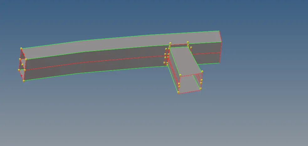
Given Model
Step 1
- Geometry Cleanup - delete unwanted lines, Clear all temporary nodes
- Connect the disconnected surfaces or joints
- Use extend surface and replace, add points tools
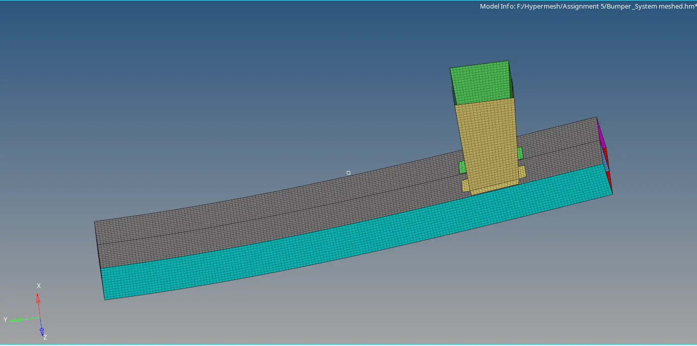
2dMesh ; size = 6mm
Step2
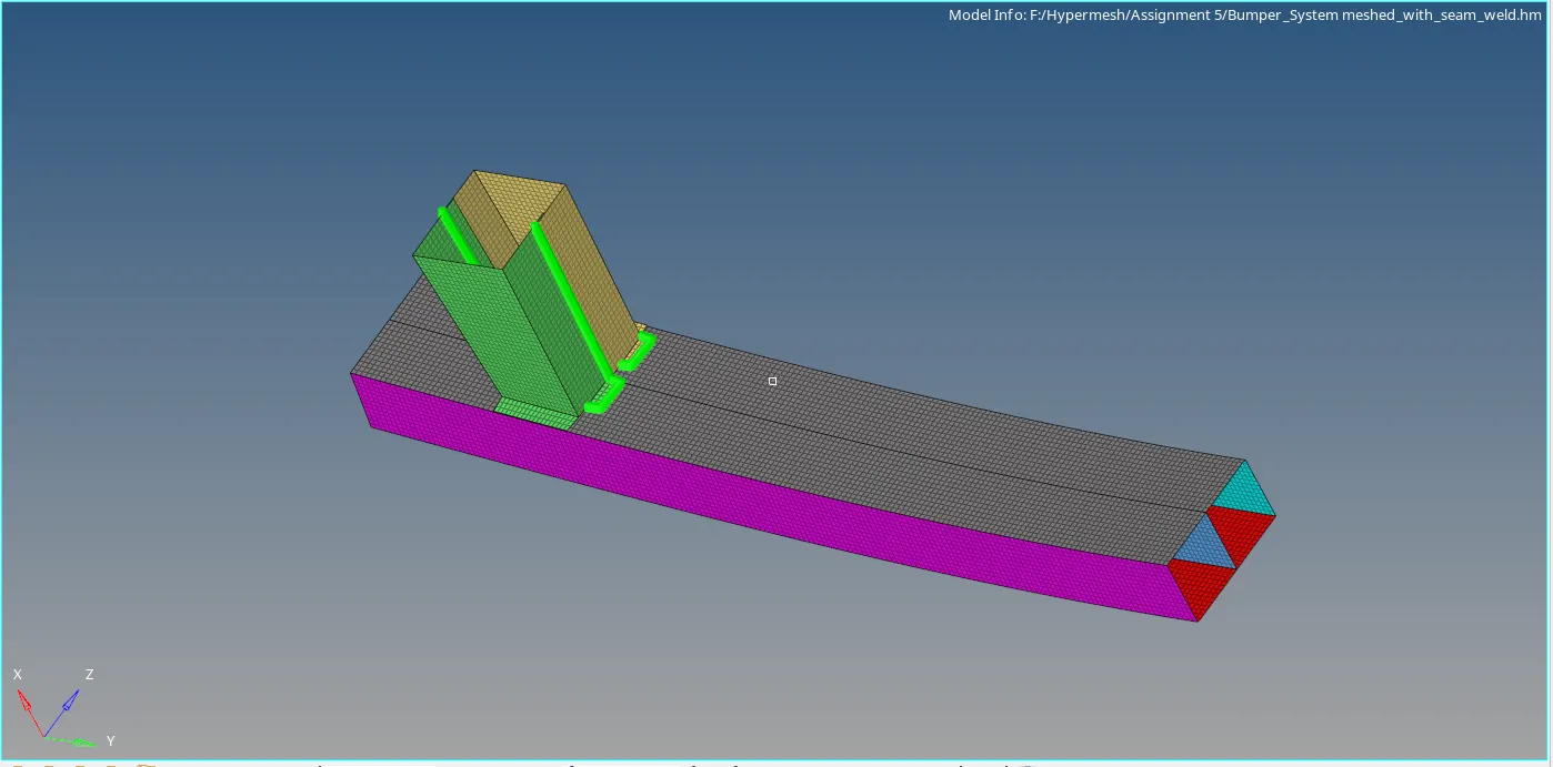
- Seam weld the free surfaces
- Go to Connectors ->Seam->Type2 Spring

Mesh with Seam weld
Case1
Crush_tube_0000.rad file is run with default values by adding Output block TH Part to obtain Energy graphs
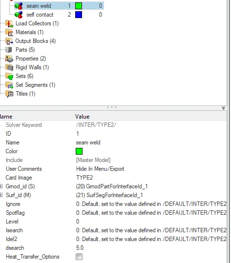
Kinematic contact was given as Seam weld for Tide contact and it is Type 2 Penalty method
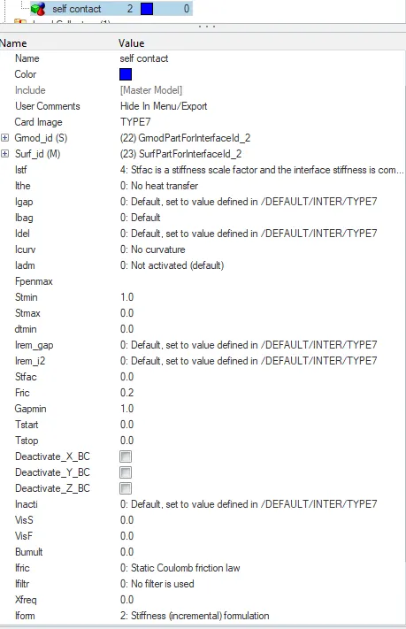
Type 7 Penalty method was used
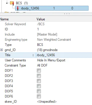
Boundary Conditions were checked
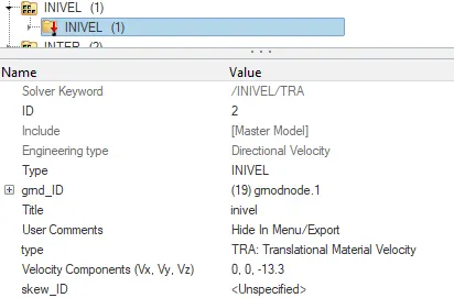
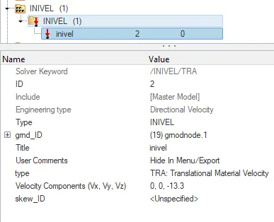
Initial Velocity conditions were checked
Output Simulation and graphs
Inference
Inputs
- Seam weld was given as Type 2 - Kinematic Contact (Node to Surface)
- Kinematic Contact/Tied Contact - The interface is defined with slave nodes which are linked to master segment
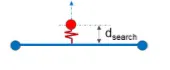 d_search = 5; Search tolerance; Average size of master segments
 - Slave nodes and Master Surface are defined
- Self Contact was given as Type 7 (master surface and a group of slave nodes)
- Buckling is possible due slave nodes belonging to master surface
- Slave nodes and Master Surface are defined
- I_stf = 4; Stiffness scale factor; k;
- `k_n` is computed from both master segment stiffness Km and slave node stiffness `k_s`
- Istf = 4, Kn=min(Km,Ks) Kn=min(Km,Ks); Interface stiffness is the minimum of the master and slave stiffness.
- Kn=min(Km,Ks) `St_min`=1; Minimum stiffness used in interface
- Kn=min(Km,Ks) Fric = 0.2; friction factor
- `Gap_min`=1; Minimum gap for activation of surface master segment
- I_form= 2; Friction formulation; where there is contact, there is friction
- Properties ; Both Shells 3.0 and 2.0 I_shell = 24; QEPH shell formulation due to which hourglass energy is 0
- Output block ; TH PART; Time history of individual parts was defined
- Rigid walls ; rwall - Engineering data- co-ordinates are selected with respect normal; direction
- Support - 2; Sliding with friction; considering interface has friction
Outputs
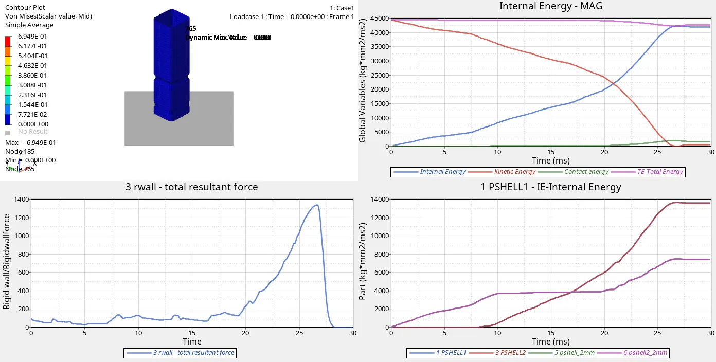
Internal Energy
Ability of body to abosorb force; the more internal energy the more impact absorbed by body
As we look into graph the internal energy is increasing with increase in impact simulataneously the deformation takes place at 27seconds the graph becomes uniform as there is no deformation or impact to absorb
Kinetic Energy
K.E = `1/2 mv^2` m- Mass; v-Velocity ; If a body is in motion, K.E acts on it
There is movement with mass due to given velocity
As we look into graph intiallly there is high K.E due to impact and deformation; at nearly 27 seconds ;it becomes straight and rebounds somewhat
Contact Energy
Energy required to push a slave node from master segment
As we look into graph intial penetration into master segment was very much less but at 23 seconds; more energy was required to avoid slave node from enetering master segment
Total Energy
It's the sum of All energies
As we look into graph it's higher than all energies; but nearly at 27 seconds it coincides with internal energy; it means the ability to absorb force in crash tube is good
R-Rigid wall Forces - Total Resultant force
It is the total impact acting on Rigid wall
Input velocity given on nodes acts on rigid wall; Rigid wall is there so that it withstands the impact
As we look into the graph resultant force was low from 20 seconds there was rise in impact and nearly at 27 seconds impact was at peak steep curve sudden increase and decrease
Part wise Internal Energy
Due to difference in shell element thickness there has been difference in internal energy graphs
p_shell 3.0 has more thickness than p_shell 2.0 ; p_shell 3.0 is able to absorb more impact compared to p_shell 2.0
- More thickness of shell more internal energy the component has.
Case 2
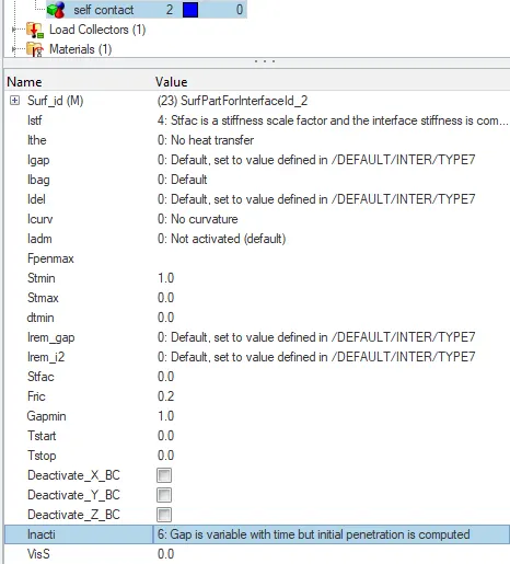
Same model analysis is done by changing Inacti=6 in Type 7 Penalty method
Output Simulation and graphs
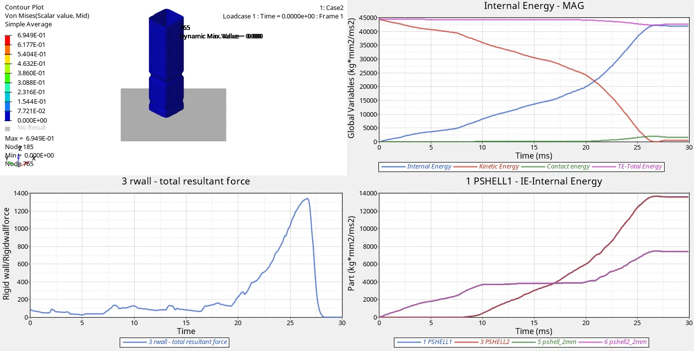
Inference
- All the conditions are same in Case2 as in Case 1 except Inacti = 6 given in Self contact Type 7
- Inacti ; Intial Interactions (Penetrations)
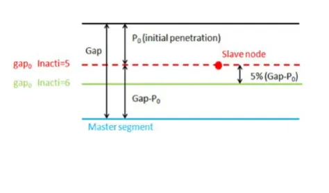

- Special lgorithm is used to check if any intial penetrations of nodes taking place on master segment before running
- If we look into graphs Case 1 and Case 2 are similar which means when Inacti=6; there were no intial penetrations before running the model.
Case3
Created Type 11 Contact Output block for Internal Energy and Analysis was done
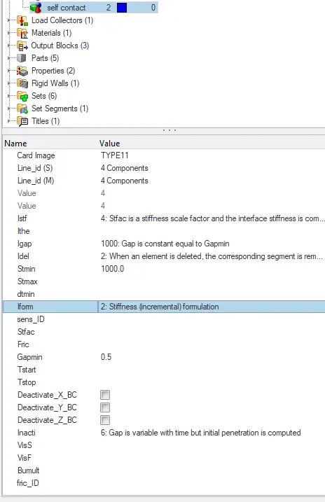
Output Simulation and graphs
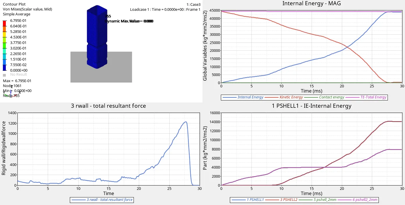
Inference
Type 11 Penalty method
- It is used for non linear impacts
- This interface simulates impact between edge to Edge or lines. A line can be a beam or truss element or a shell edge or spring elements.
- In Type 7 Contact ; In Node to Surface contact ; error occurs as the node passes the surface without deformation; To capture edge to edge deformation Type 11 interface is used.
- Contact Energy of Case 1,2 (Type 7 )Node to Surface Vs Case 3 (Type 11 ) Edge to Edge
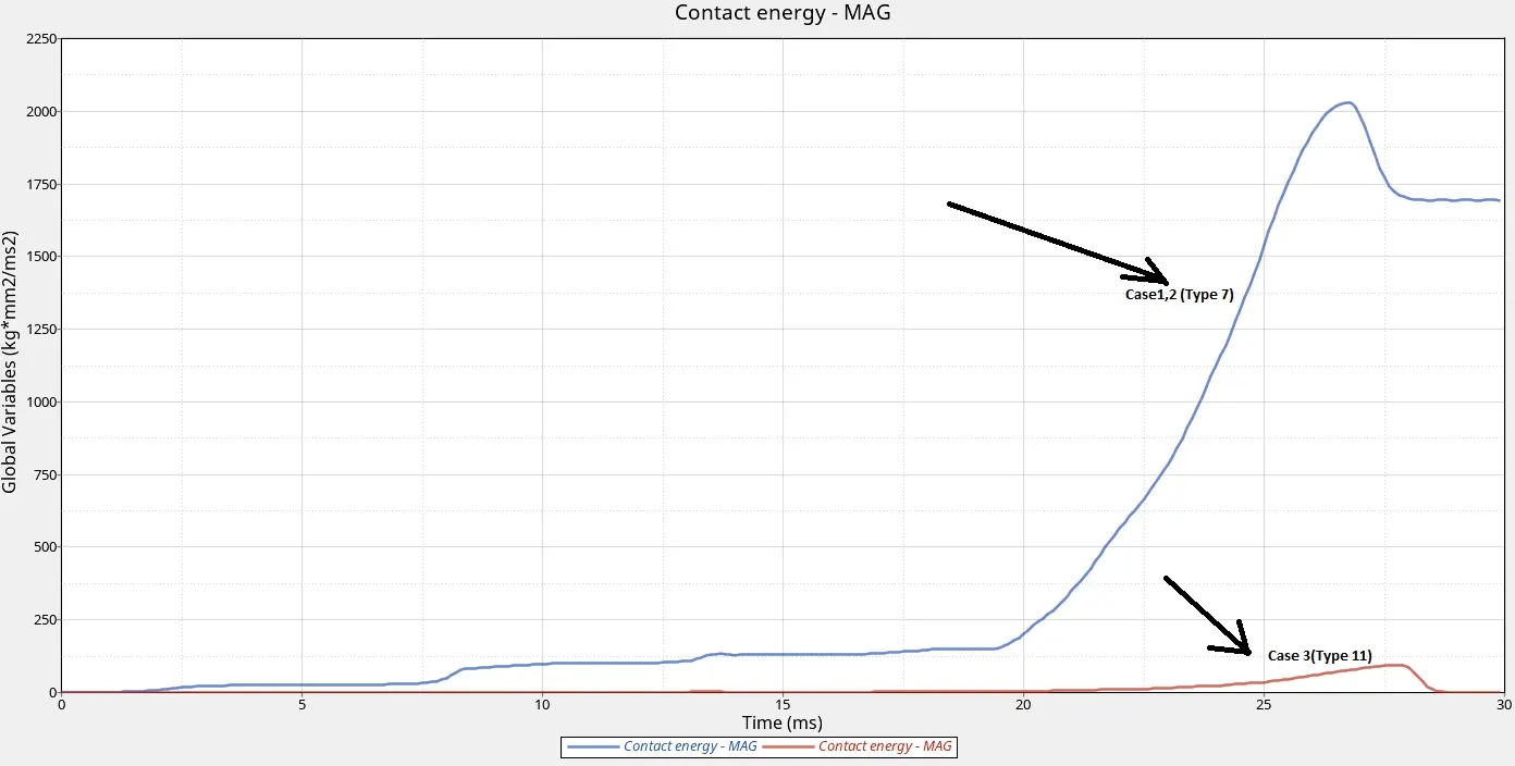
If we look into graph there has been tremendous difference in Contact Energy
Type 7 being node to surface type contact requires more contact energy to push slave nodes from reaching master segment
Whereas in type 11 being Edge to edge contact, is an advantage over type 7 less contact energy is required to push slave nodes from master segment.
Rigid wall force has been reduced due to Type 11 contact
Case4
Same model All the notches and boundary conditions on the rigid body are removed and analysis was done
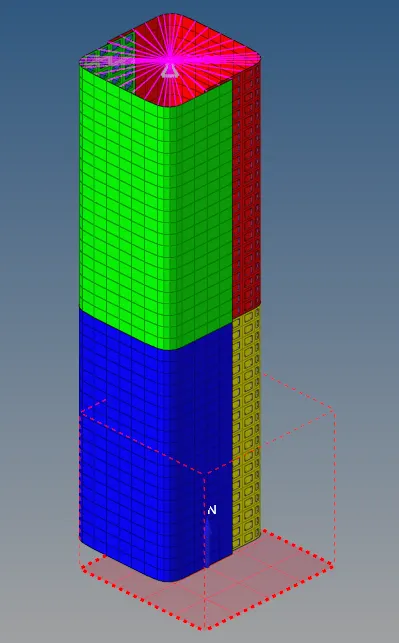
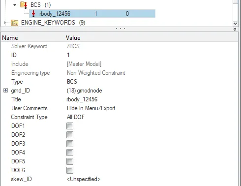
Output Simulation and graphs
Inference
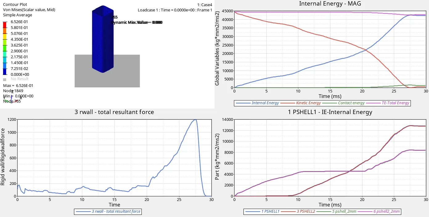
As both notches are removed, the impact acting on rigid body is 1200N which is less compared to impact acting in case 1,2 &3 is 1350N due effect of flat surface.
Vonmises stress has decreased
Contact Energy (Case1 with boundary conditions and notches Vs Case 4 No boundary conditions and notches)
Kinetic energy is almost same.
Due to thickness difference there is variation in internal energy of shell.
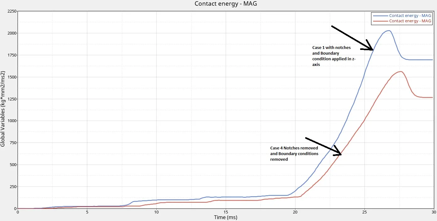
As we can look into graph it's clear that due to absence of notch and ; less energy is required to push slave node from master segment
Internal Energy is reduced slightly compared to case1 due to removal of boundary condition.
Case5
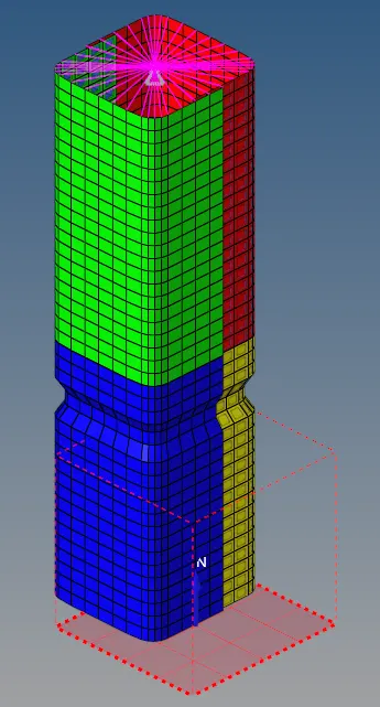
Same Model create a notch in the middle and analysis was done
Output Simulation and graphs
Inference
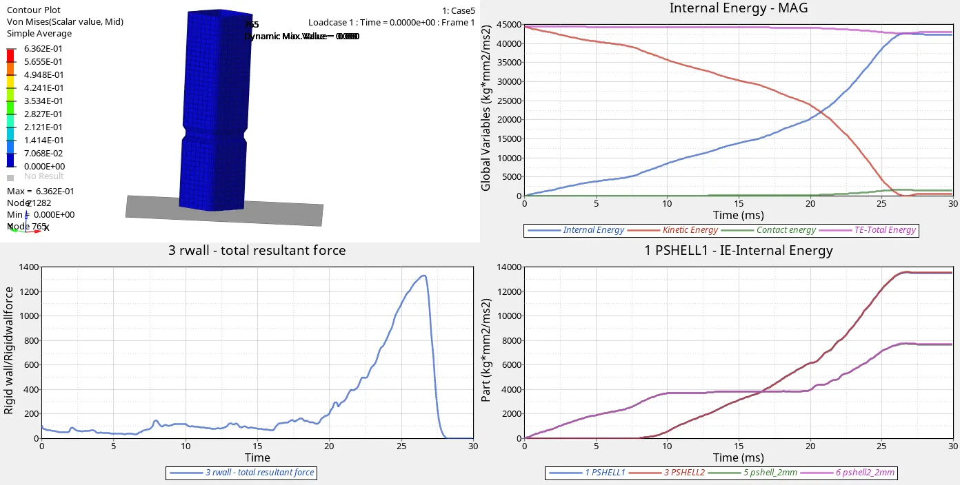
Von mises stress is reduced
Force on Rigid wall has increased compared to case 4
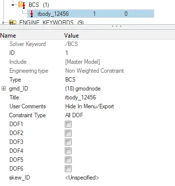
Internal energy is almost similar to case 4 as boundandary condition is not given
Deformation at starting point can be seen in initial stages itself
Case1 (2 notches ) Vs Case 5 (middle notch) Contact Energy
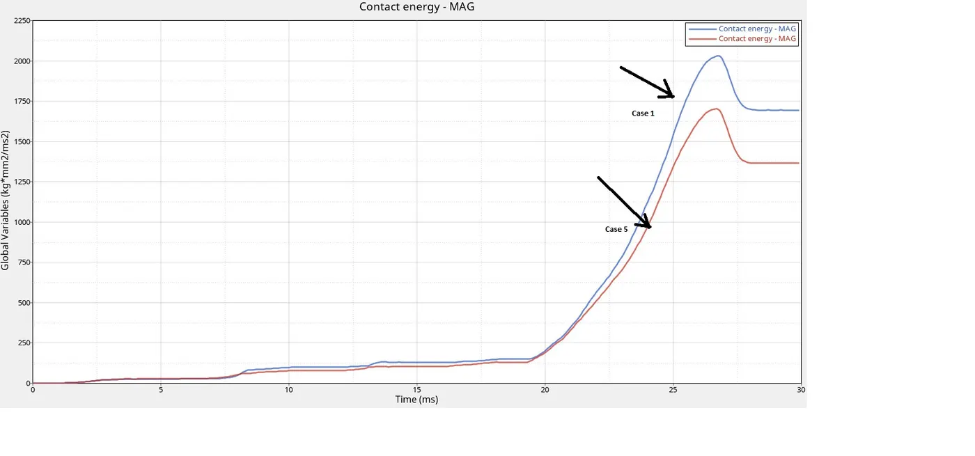
- Contact energy has decreased compared to case1(with 2 notches) and increased compared to case4(no notches) because as single notch is there less contact energy required to push slave node away from master segment.
Case 6
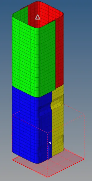
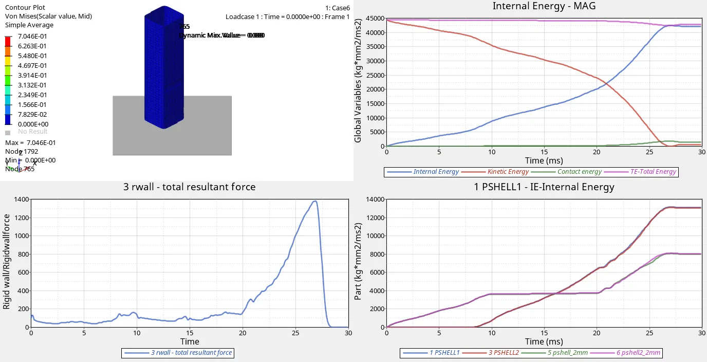
Created notch with nodes only from two opposing faces and analysis was done
Output Simulation and graphs
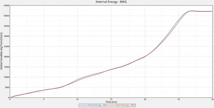
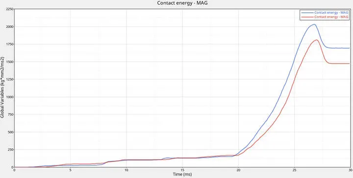
Case 1(2 Notches all sides ) Vs Case 6 (2 Notches Opposing faces ) Internal and Contact Energies
Inference
Von mises Stress is higher than any other case
Rigid wall force is almost similar to previous case
Internal energy slight variation due to removal of boundary condition
Contact energy less compared to case1 and greater than case5 ; that means notch in opposing faces required more contact energy than that of case 5(single notch)
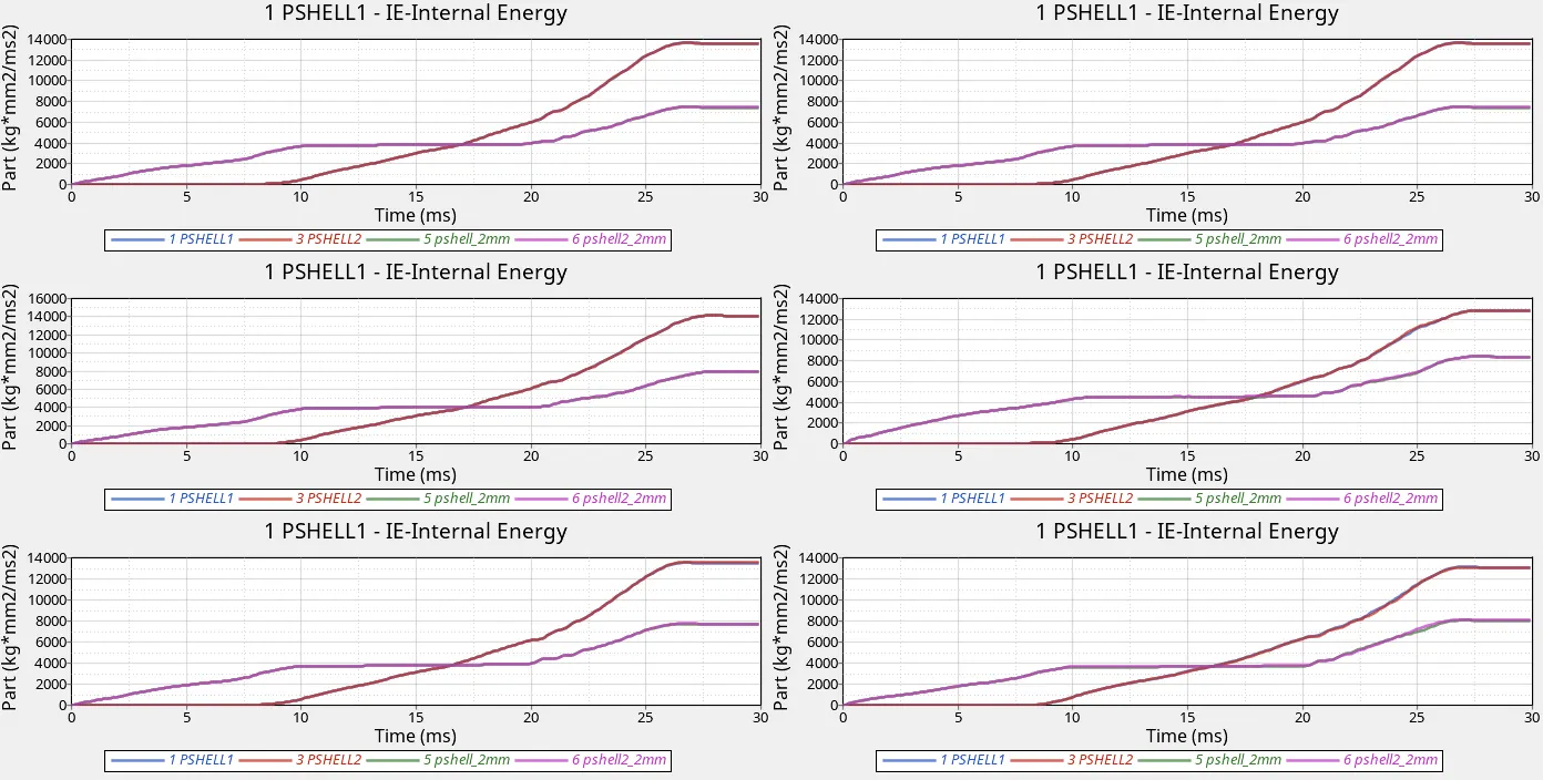
Internal Energy by Parts All Cases
Inference
Thickness properties of both shells vary Shell 3.0 has 3mm thickness while shell 2.0 has 2mm thickness so, more and faster deformation is seen in shell 2.0 then in shell 3.0
Thickness Properties
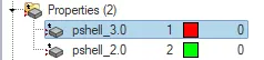

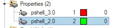

Variation in Internal energies is due to difference in shell thickness
- 3mm shell is requires higher internal energy; it means ability to absorb force is higher in shell with 3mm thickness compared to shell with 2mm thickness
- More thickness of shell more internal energy the component has
Internal Energy Cases-1,2,3,4,5,6
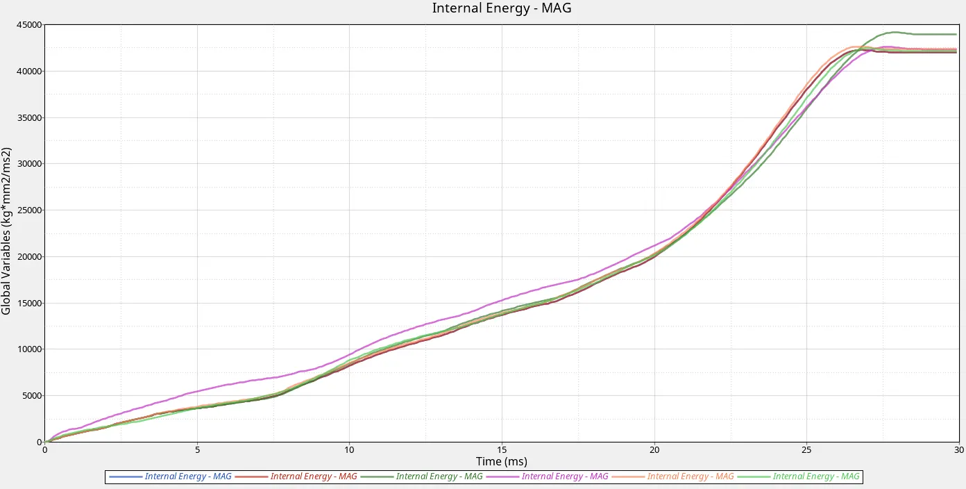
Inference
- If we look into the Internal energies of all cases Internal Energy is varying
- The ability of abody to absorb force is Internal Energy
- So, if internal energy is high then component has good impact absorbing capability
- High internal Energy is recommended which can be seen in case 3 with type 11 contact
- Type 11 interface can be used in addition toType 7 to solve the edge to edge limitation of interface TYPE7.
Conclusion
| Cases | Condition | Result | Reason |
| Case 1 | 2 Notches with Boundary condition | High Contact Energy; Internal Energy less compared to Case 3 | Node to Surface Contact Type 7 |
| Case 2 | 2 Notches Boundary condition Inacti=6 | Same results as Case 1 | No Intial Penetrations found |
| Case 3 | Type 11 Contact | Lowest Contact Energy; Highest Internal Energy | Type 11 Edge to Edge Contact |
| Case 4 | Remove notches and boundary condition | Low contact energy compared to case1 ; Low Internal Energy | No boundry condition; flat surface |
| Case 5 | Put notch in middle no boundary condition | Internal Energy slightly more than case 4; Contact energy more compared to case4 | ability to absorb increased due to middle notch |
| Case 6 | notch in opposing faces and no boundary condition | Slight increase in Internal Energy compared to case 5 similar to case1 ; Contact Energy more compared to case 5 | due to Opposing notches |
- Boundary conditions are limited to rigid wall; As we can see in animation when boundary conditions were removed there was deformation in crash tube from top faster than compared to conditions where boundary conditions were given
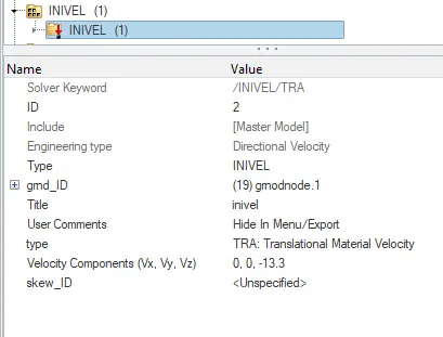
- Initial Velocity is given to each and every node; need to check this condition for correct analysis
- Type 7 Contact is node to surface contact; act as auto contact; outputs are seen in case 1,2,4,5,6
- Type 11 contact is edge to edge contact ; outputs are seen in case 3
- To get bettter results Type 11 interface can be used in addition toType 7 to solve the edge to edge limitation of interface TYPE7.
- Energy factors may be considered based on circumstances; Cases where high internal energy required to get that body absorbs high impact
- In case of Contact energy; slave node interference with master segment (Node to surface or Edge to edge)
- Low contact energy and high internal energy can be considered based on Componenet and properties
- Notch has good role in increasing Internal energy and Contact energy