Assignment 5
1) Objective: To create the mesh for bumper assembly with a mesh size of 6mm.
Execution :
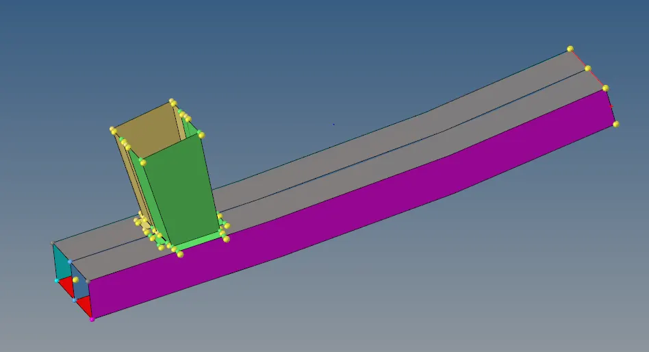
- first, open the given file and toggle the edges with the required tolerance
- now mesh all the 8 components starting from bumberbeam_rear and moving up with element size as 6
- check for tria elements and remove them, make sure all the elements are quads.
- after meshing :
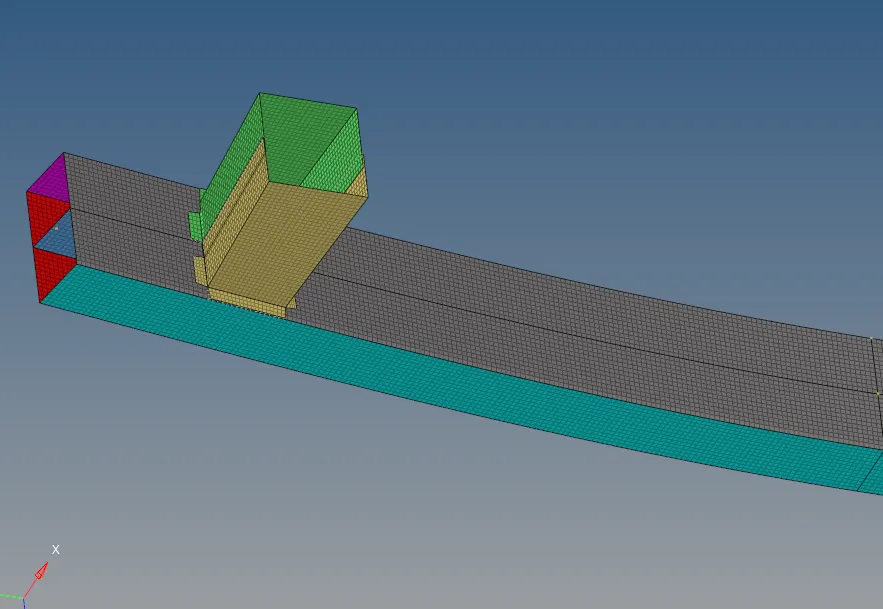
- once the meshing is done we move on to welding
- goto 1-D ---> connectors ---> seam
- now under seam select node path with spacing = 6 and give required tolerance and select the components to be welded.

- weld all the edges of crash_box_lower and crash_box_upper
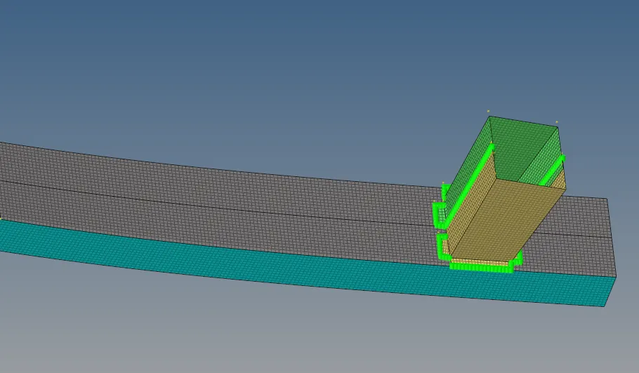
- this is only one half the component, now we use the reflect option to reflect this component on the other side to form a complete bumper system
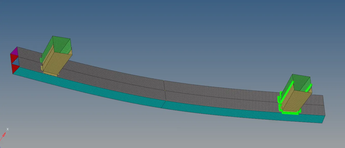
the above model is the completed bumper component.
--------------------------------------------------------------------------------------------------------------------------------------------------------------------------------------------------------------------------------------------------------------------------------------------------------------
2) Objective: import the given solver model and run the following cases
case 1: Run the crash tube model as it is
case 2: Change the Inacti=6 and run
case 3: Create the type 11 contact and run
case 4: Remove both notches and remove boundary condition on rigid body node then run
case 5: Create a new notch in the middle, select the whole section, and run.
case 6:Create a new notch with nodes only from opposing 2 faces and run.
Execution :
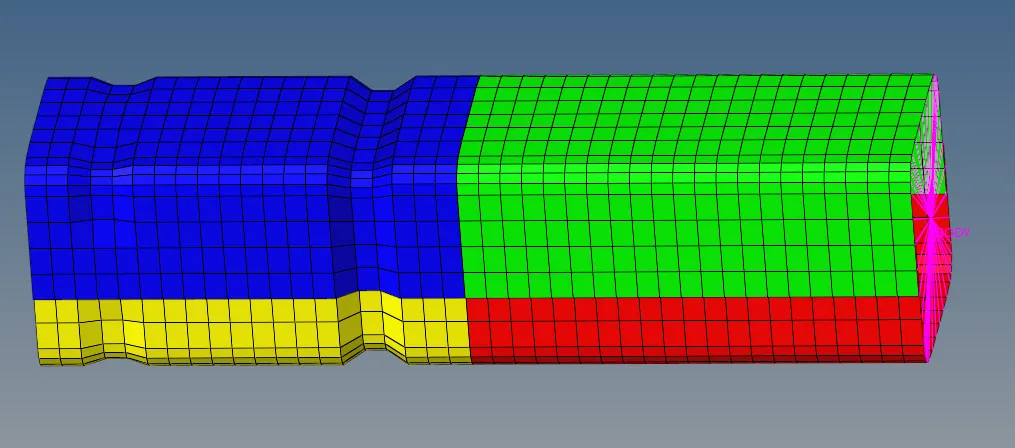
case 1: we import the given crash tube solver model and run it as it is
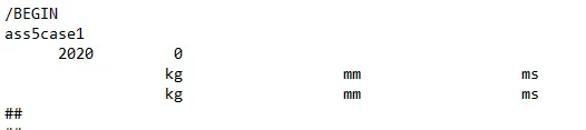
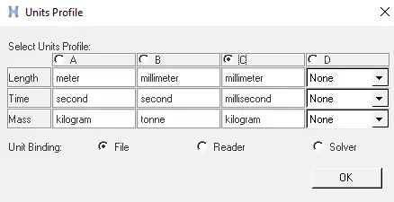
the units inputted in the unit profile
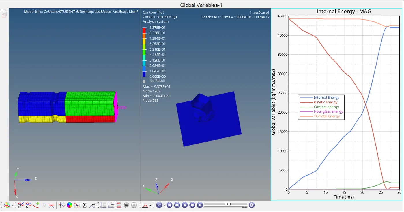
from the graph and contour plot, we can observe that the max contact force is 9.378E+01
the kinetic energy decreases with an increase in internal energy
the internal energy increases exponentially till t=20 ms and rises quickly at t=28 and it's stable after
the internal energy and total energy intersect each other at maximum deformation
the kinetic energy decreases exponentially and reaches 0 at t=27 ms indicating complete deformation
at t= 28 ms there is a slight deformation due to reaction force from the rigid wall, this can be observed more clearly by increasing the time steps
kinetic and internal energy intersect each other and are equal at t=22 ms
hourglass energy is 0
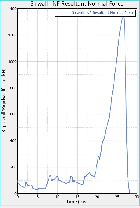
the rigid wall forces increase with each minor deformation and there is a huge spike in rigid wall force when the complete deformation occurs
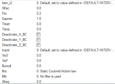
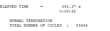
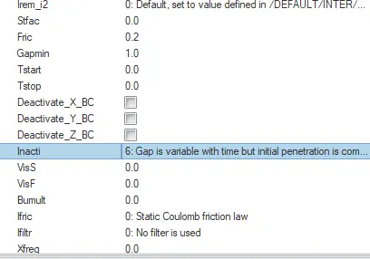
case 2: we change the value of inacti = 6 and run the model
type 7: Interface TYPE7 is a multi-usage impact interface, modeling contact between a master surface and a group of slave nodes. It is also possible to consider heat transfer and heat friction.
with incati set to 6, we get good element capture, accuracy and it's scaled
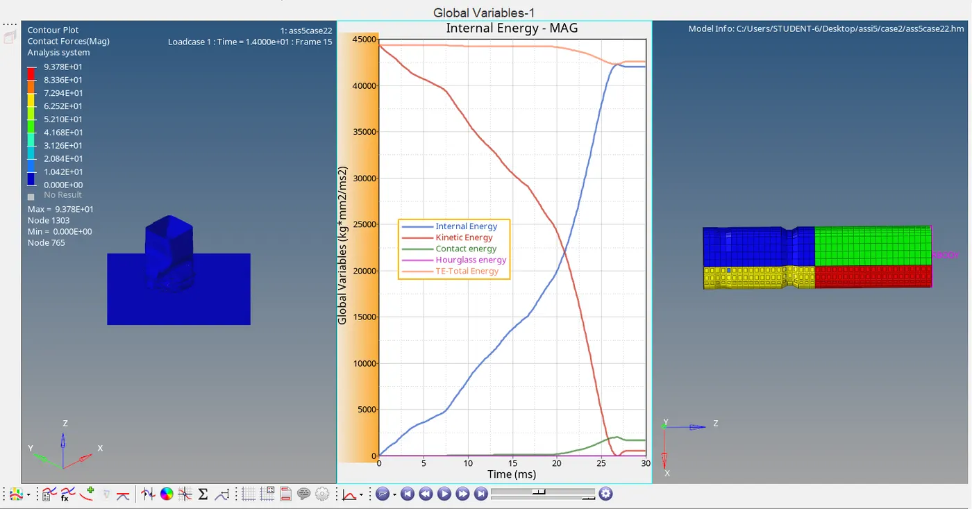
from the graph and contour plot, we can observe that the maximum contact force is 9.378E+01
the kinetic energy decreases with an increase in internal energy
the internal energy increases exponentially till t=20 Milli sec and rises quickly at t=28 and it's stable after
the internal energy and total energy intersect each other at maximum deformation
at t= 28 ms there is a slight deformation due to reaction force from the rigid wall, this can be observed more clearly by increasing the time steps
the kinetic energy decreases exponentially and reaches 0 at t=28 Milli sec indicating complete deformation
the contact and kinetic energy intersect each other at t=26 milli sec
kinetic and internal energy intersect each other and are equal at t=22 milli sec
hourglass energy is 0
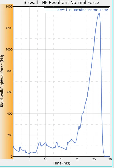
the rigid wall forces increase with each minor deformation and there is a huge spike in rigid wall force when the complete deformation occurs
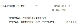
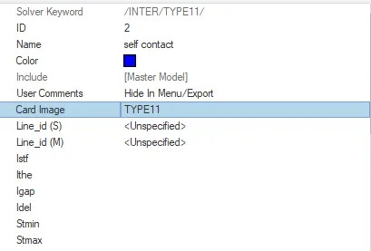
case 3: change the type to type 11 contact and run
type 11: This interface simulates the impact between edge to Edge or lines. A line can be a beam or truss element or a shell edge or spring elements.
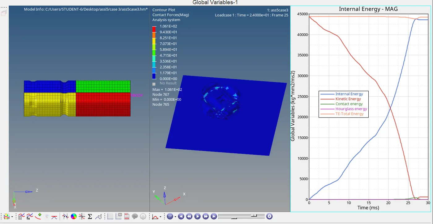
from the contour plot, we can observe that the maximum contact force is 1.061E+02
internal, kinetic, contact, energies are plotted in the graph and can be observed that the total energy remains constant and there is a slight deviation when complete deformation occurs
at t= 28 ms there is a slight deformation due to reaction force from the rigid wall, this can be observed more clearly by increasing the time steps
the internal energy increases exponentially and reaches a peak at complete deformation and intersects total energy
contact energy stays at 0 and rises only at t=28 ms (at the time of deformation)
internal energy increases with a decrease in kinetic energy at complete deformation
hourglass energy is 0
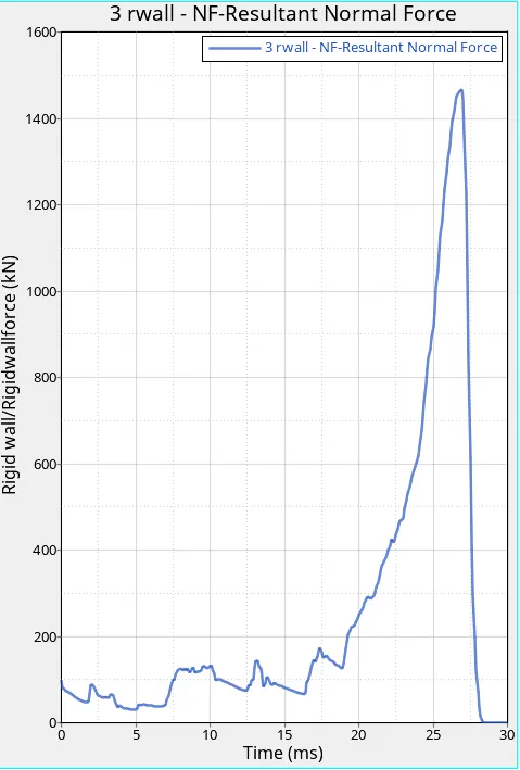
the rigid wall forces increase with each minor deformation and there is a huge spike in rigid wall force at t=28 ms when the complete deformation occurs
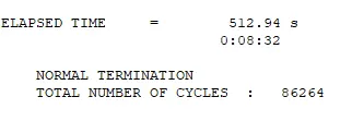
case 4: Remove both notches and remove boundary conditions on a rigid body node then run.
first, we remove all the notches by using the node replace option by going to node edit

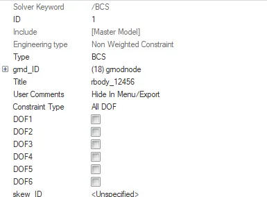
once all the notches are removed we remove the boundary conditions and then run it
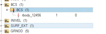 we can either directly delete from here or
  untoggle them manually
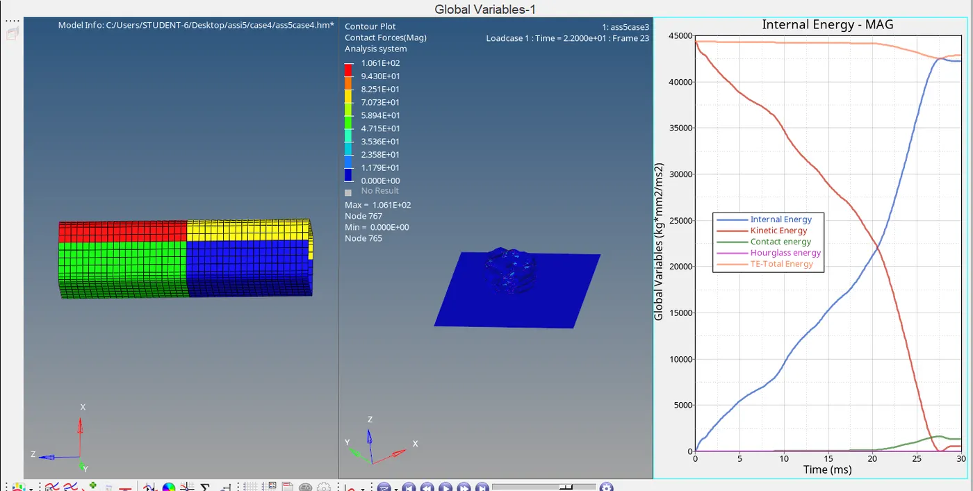
from the contour plot, we can observe that the maximum contact force is 1.061e+02
from the graph, we can observe that at maximum deformation kinetic energy decreases steeply and internal energy increases steeply, this is due to the work done in deformation
hourglass energy is 0
contact energy slowly increases from t=20 ms and rises steadily until deformation
at t=28 ms the elastic deformation takes place and hence the slight spike in energies at that point.
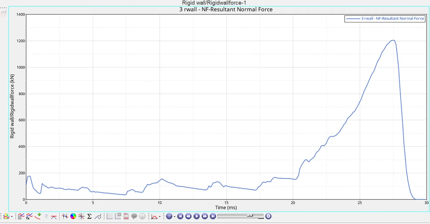
as we can see there are minor deformations taking place till t= 27 ms and from t=27 ms there is a huge spike indicating complete deformation
case 5: create a new notch in the middle and, select the whole section and run
for this case first, we use the two nodes option to find the length of each component

we found the distance of the yellow component to be 148.59 and the red component to be 156.
so, now using the align node option we create a notch on the red component

now save the file and run radioss
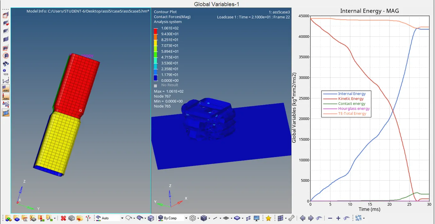
the maximum contact force is 1.061E+02
there is a steep decline in kinetic energy at the point where initial deformation takes places at the notch created and there is also an increase in internal energy at that point
hourglass energy is 0
there is a huge peak in internal energy values during final deformation and kinetic energy drops to zero and thsi polint
contact energy increase steadily but rises at t=26 sec
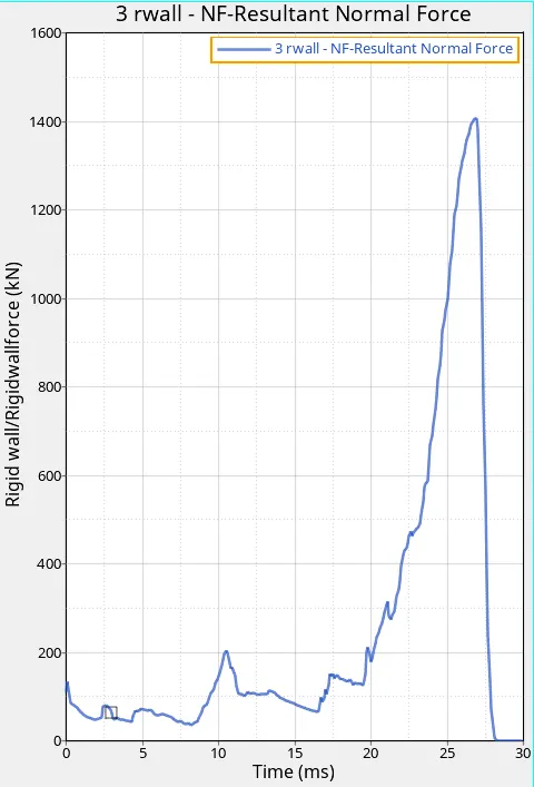
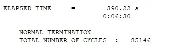
there is a spike at t=10 ms indicating initial deformation before notch and a huge spike at t=25 ms indicating final deformation.
case 6: Create a new notch with nodes only from opposing 2 faces and run.
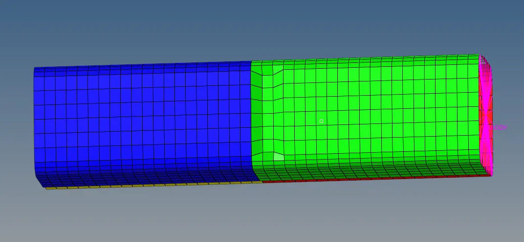
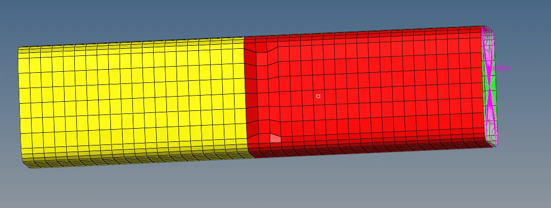
first, we hide red and yellow components and create notches on the face of the green component and then repeat the process for the other side
save the model and run radioss
the notches are made using the node edit option
select align node and then choose 2 reference points on the surface and choose the surface nodes to be alligned with
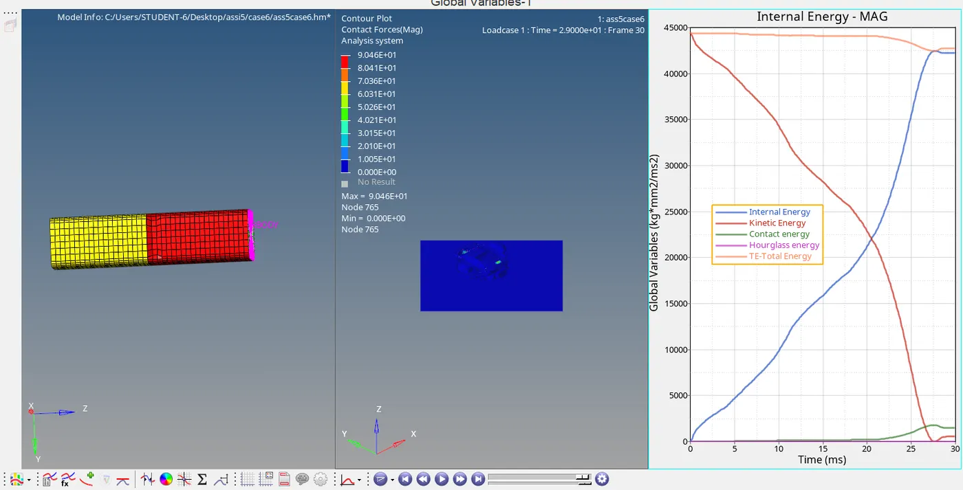
it can be observed from the contour plot that the maximum contact force is 9.046E+01
hourglass energy is 0
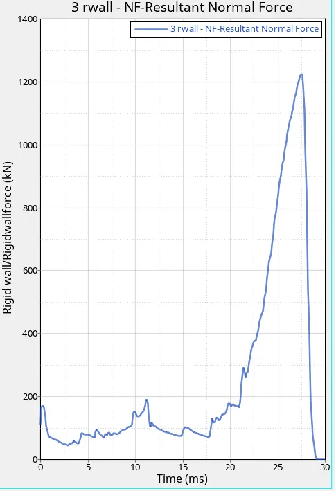
from the graph plotted it can be noticed that the energies spike at the places where notches are created and the resultant normal force also spikes at the places pf deformation
kinetic energy decreases with an increase in inbternal energy
due to the work done on deformation, the kinetic energy is converted into internal energy
CONCLUSION: the contact force is maximum in case 6 and internal energy increases with a decrease in kinetic energy but there is a point where both these energies have the same value and that point is the point of deformation.