Contact Interface Modeling Using Type-7 and Type-11 in Hypermesh
AIM :
To create mesh for bumper Assembly and to run the crash tube model as per following conditions and Plot Rigid Wall Force, Contact Forces, Internal Energy and to create TH/PART for all parts and compare results for all cases.
OBJECTIVE :
Sudy-1 : Bumper Assembly
1. Creating Mesh for bumper Assembly, mesh size should be 6mm.
Study-2 : Crash Tube
1. Run the Crash Tube Model as it is,
2. Change the Inacti=6 and run,
3. To create Type 11 contact and run the simulation for Crashtube Model,
4. Remove both notches and remove boundary condition on rigid body node and run,
5. Create a new notch in the middle ,select the whole section and run,
6. Create a new notch with nodes only from opposing 2 faces and run.
THEORY :
Contact Interface Modeling :
The explicit analysis method efficiently solves complex dynamic contact problems (boundary condition nonlinearity). Accurate modeling of contact interfaces is essential to correctly capture contact interaction between bodies. RADIOSS has a large number of contact types suitable for many applications. In RADIOSS an interface is created by defining the master segment and slave node set. The master segment can be parts components, elements, contact surface, node surface sets and slave entities can be parts components and node sets. The contact algorithm will check every time step for potential penetration of a slave node through a master segment. If penetration is detected the contact is treated with either a Penalty or Lagrange multiplier method.
Penalty Method :
Interfaces using the penalty method are based on master/slave treatment. Contact can only occur between a set of slave nodes and a set of master segments. Master segments are defined depending on the type of element they lie on.
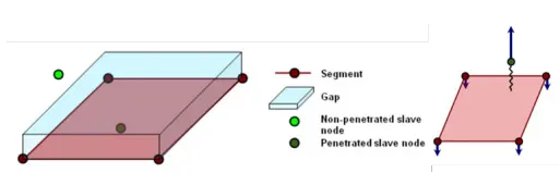
Fig : Penalty Method
Interface Type-7 : Nodes to Surface Contact :
- Automatic node to surface contact interface using penalty method with variable
stiffness
- A gap is defined around the master segment and the slave nodes
- The contact gap can be constant or variable
- Resistive forces are applied to keep slave nodes out of the contact gap
- Interface time step is computed to insure stability
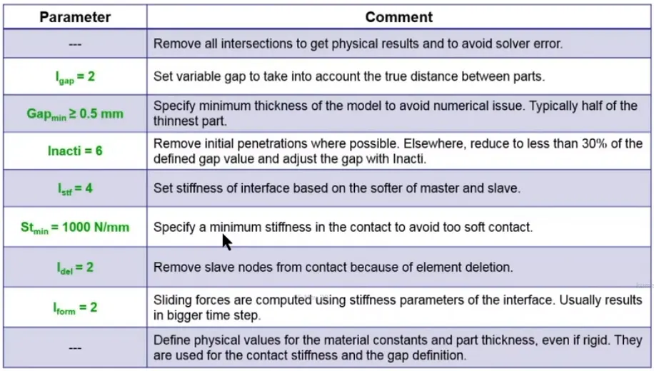
Fig : Recomended Contact Parameters for Interface Type-7
Options for Removing Initial Penetrations :
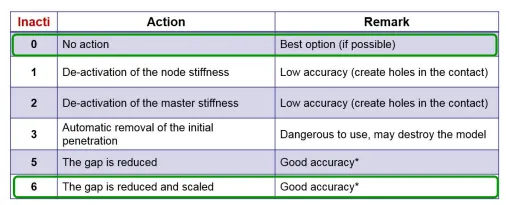
The initial penetration, P0 should be smaller than 30% of the initial gap to avoid contact stability issues
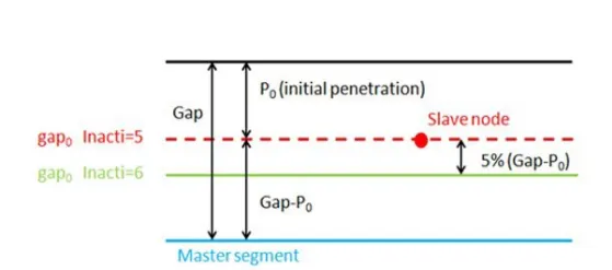
Fig : Inacti 5 and Inacti 6
Interface Type-11 : Edge to Edge Contact :
- This interface simulates impact between edge to Edge or lines. A line can be a beam or truss element or a shell edge or spring elements. In association with interface TYPE7, interface TYPE11 solves the locking cases
- Defined by identifying master and slave lines (edges)
- Impacts occur between a master and a slave line. A slave line can impact on one or more master lines. A line can belong to the master and the slave side. This
allows self-impact.
- Works similar to Type 7 in terms of Penalty formulation, Gap definition and Search method
- Uses complicated mathematical algorithms; therefore, it is strongly advisedto use it only when necessary. A huge interface TYPE11 can slow down the computation.
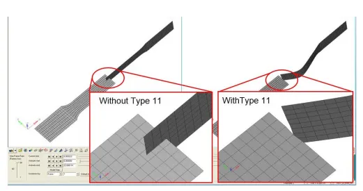
Fig : Interface Type-11 : Edge to Edge Contact
PROCEDURE :
STUDY - 1 : BUMPER ASSEMBLY
1. Open the Bumper Assembly model using File-->Open-->Model option.
2. Clearing unwanted nodes using tempnodes-->clear all option.
3. Check for the Geometry error and connections in the model.
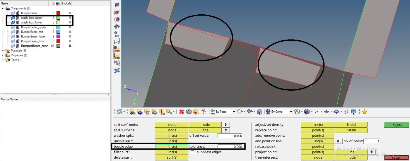
Fig : Geometrical Error
4. In the above figure, identified error in the model, Go to Components and show crash_box upper and lower components and hide other components.
5. Error will be cleared by using Geom-->quick edit-->toggle edge option, setting tolerance value as 2 and toggle those two lines.
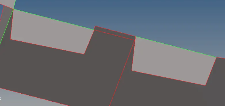
Fig : After Geometry Celan up
6. After Cleaning Geometrical Error, Start Meshing by using 2D-->automesh and Select the all Surfaces and set element size as 6mm and click mesh.
7. Remove tria elements by increasing or decreasing the elements to equal on both sides.
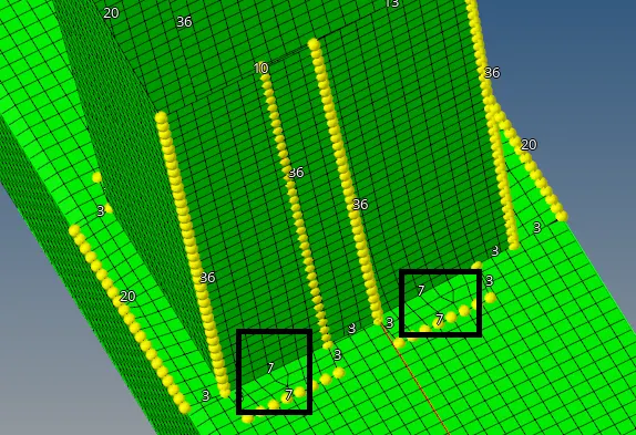
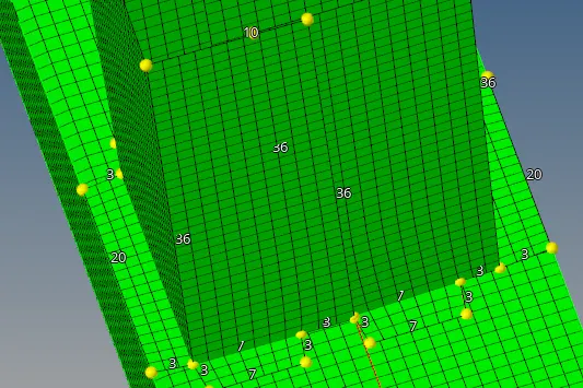
Fig : Before Removing tria elements Fig : After Removing tria elements
8. After Meshing, Weld Crash_box_upper and Crash_box_lower component by using 1D-->Connectors-->Seam option.
9. In seam weld, Select location as node-->by path, set type as type2(Spring single row) and select the nodes & Components and Create Weld.
10. Crash_box_upper, Crash_box_lower is welded with eachother and with Bumperbeam_rear.
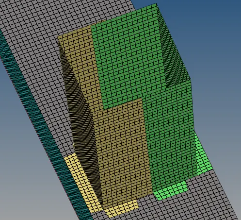
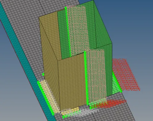
Fig : Before Weld Fig : After Weld
STUDY-2 : CRASH TUBE
Case-1 : Default Simulation (Type-7 Contact)
1. Import the Crash Tube Model in Hypermesh(Radioss) by using Import icon and select the Crush_tube_0000.rad file and click Import.
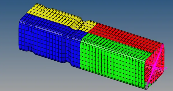
Fig : Crash Tube Model
2. After Importing the model, Run the Simulation by keeping default Model with Type-7 Contact Parameters as it is.
3. Creating Time History(TH/PART), by using Solver-->TH and Create Part for all parts.
4. Go to Analysis-->Radioss option and Save the input file in new folder and set options and run the simulation.
5. Change Hypermesh into HyperView and load the Crush_tube.h3d model file and Click Apply.
6. Select the Contour icon and set Result type as Displacement(v), Contact Force(v), Vonmises (s) and click Apply.
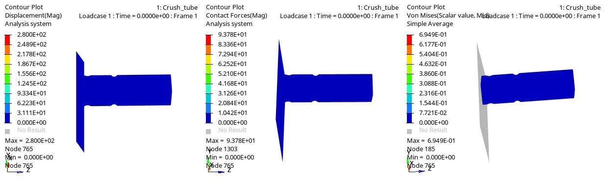
Fig : Displacement Plot Fig : Contact Force Plot Fig : Vonmises Stress plot
7. From the above Contour Plots observed that,
- Crash Tube is impact on the Rigid Wall, Deformation(strain rate) will occur. Maximum Displacement is 2.800E+02,
- Contact Force is force required contact to occur between Master & Slave Node, Here Maximum Contact force is 9.378E+01 N,
- While deformation occurs stress will be created, Maximum Stress is 6.949E-01 `N/(mm)^2`
8. After Plotting contour plots, Change HyperView into HyperGraph 2D to plot the Energy as a function of time.
9. Load the time history file Crush_tubeT01 file.
10. Select the Y-type,Y-Request and Y-Component as Global Variables-->Internal Energy, Kinetic Energy,Contact Energy,Total Energy-->Mag and Rigidwallforce-->3wall-->total resultant force and click Apply.
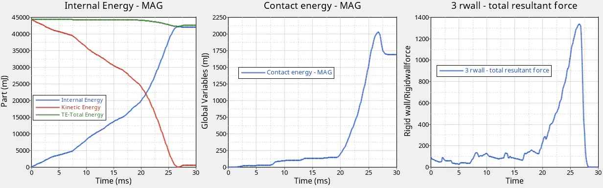
11. From The above plot,
- Crash Tube is impact on the Rigid wall, Internal Energy is starts to gain the energy of the system due to changes in its internal state and Kinetic Energy starts to lose the energy of the system. We know that Total Energy is the sum of Internal Energy and Kinetic Energy. So when the Internal Energy gains and Kinetic Energy loses, Total Energy should be stable. After the Element reaches the Reference strain rate, Some opposite reaction force will created, due to opposite force some amount of kinetic energy increases and Total Energy is not stable at the time(27 ms) of Opposite force is applied. 42500 mJ Internal Energy is maximum energy generated.
- Contact Energy is Combination of Penetration and Contact Force (between Master & Slave Nodes). While crashing happens,Contact Force is a force applied between Master & Slave nodes and energy required to resist the Penetration of Master & Slave Node, So that Contact Energy is increased upto 2000 mJ. After Element reaches the Reference Strain rate(time = 27 ms), Contact Energy will be decreased to 1700 mJ due to Opposite force applied.
- When the Crash tube is impact on the Rigid wall, Force will be created on the point of contact between rigid wall and crash tube. 1300 N Rigid Wall Force is maximum force.When the material reaches the reference strain rate, at that time rigid wall force will be sudden decrease due to oppsite force happens.
Case-2 : Changeing Inacti=6 in Type-7 Contact
1. In case-2, Import the same model Crash_tube_0000.rad file used in Case-1.
2. Change Inacti=6 in Type-7 Contact Parameters and Creating Time History(TH/PART), by using Solver-->TH and Create Part for all parts.
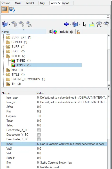
Fig : Changing Inacti=6 in Type-7
3. Run the simulation using Analysis-->Radioss option and Save the input file in new folder and set options and Click Radioss.
4. Change Hypermesh into HyperView and load the Crush_tube.h3d model file and Click Apply.
5. Select the Contour icon and set Result type as Displacement(v), Contact Force(v), Vonmises (s) and click Apply.
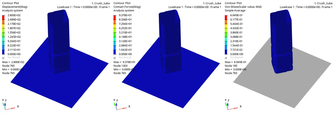
Fig : Displacement Plot Fig : Contact Force Plot Fig : Vonmises Stress plot
6. From the above Contour Plots observed that, Maximum values of Displacement(Strain rate)=2.800E+02, Contact Force = 9.378E+01 N and Vonmises Stress = 6.949E-01 `N/(mm)^2`. Comparing to Case-1 same values are obtained. From that there is no difference by changing Inacti = 6.
7. After Plotting contour plots, Change HyperView into HyperGraph 2D to plot the Energy as a function of time.
8. Load the time history file Crush_tubeT01 file.
9. Select the Y-type,Y-Request and Y-Component as Global Variables-->Internal Energy, Kinetic Energy,Contact Energy,Total Energy-->Mag and Rigidwallforce-->3wall-->total resultant force and click Apply.
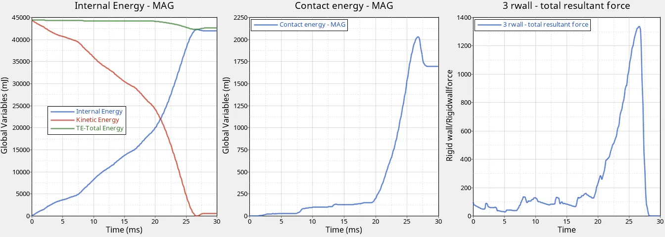
10. From The above plot,
- 42500 mJ is the maximum Internal Energy generated for Impacting the Crash tube on Rigid Wall. After the Element gets fully crashed, Some opposite reaction force will created, due to opposite force some amount of kinetic energy increases and Total Energy is not stable at that time of Opposite reaction happens.
- 2000 mJ is the Maximum Contact energy required to contact occured between Master & Slave Node. After Element reaches the Reference Strain rate, Contact Energy will be decreased to 1700 mJ due to Opposite force applied.
- 1300 N Rigid Wall Force is maximum force. When the material reaches the reference strain rate, at that time rigid wall force will be sudden decrease due to oppsite force happens.
Case-3 : Creating Type-11 Contact
1. In case-3, Import the same model Crash_tube_0000.rad file used in Case-1.
2. Create the Type-11 Contact in the Interface and Type-7 Recomended Parameters are defined for Type-7 & Type-11 Contact.
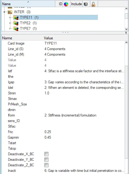
Fig : Type-11 Contact with Recomended Parameters
3. After defining the Parameters, Create Time History(TH/PART), by using Solver-->TH and Create Part for all parts.
4. Run the simulation using Analysis-->Radioss option and Save the input file in new folder and set options and Click Radioss.
5. Change Hypermesh into HyperView and load the Crush_tube.h3d model file and Click Apply.
6. Select the Contour icon and set Result type as Displacement(v), Contact Force(v), Vonmises (s) and click Apply.
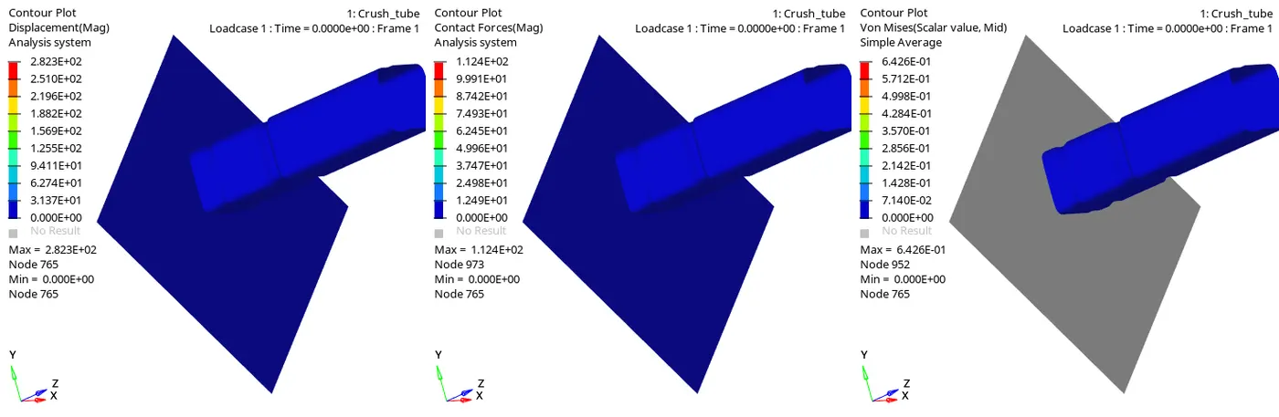
Fig : Displacement Plot Fig : Contact Force Plot Fig : Vonmises Stress plot
7. From the above Contour Plots observed that, Maximum values of Displacement(Strain rate)=2.823E+02, Contact Force = 1.124E+02 N and Vonmises Stress = 6.426E-01 `N/(mm)^2`.
8. After Plotting contour plots, Change HyperView into HyperGraph 2D to plot the Energy as a function of time.
9. Load the time history file Crush_tubeT01 file.
10. Select the Y-type,Y-Request and Y-Component as Global Variables-->Internal Energy, Kinetic Energy,Contact Energy,Total Energy-->Mag and Rigidwallforce-->3wall-->total resultant force and click Apply.
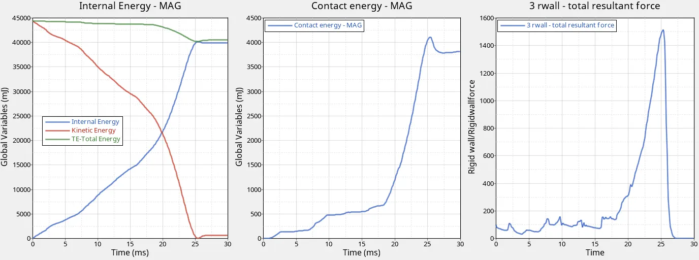
11. From The above plot,
- 44000 mJ is the maximum Internal Energy generated for Impacting the Crash tube on Rigid Wall. After the Element gets fully crashed, Some opposite reaction force will created, due to opposite force some amount of kinetic energy increases and Total Energy is not stable at that time of Opposite reaction happens.
- 4100 mJ is the Maximum Contact energy required to contact occured between Master & Slave Node. After Element reaches the Reference Strain rate, Contact Energy will be decreased to 3750 mJ due to Opposite force applied after 25 ms.
- 1500 N Rigid Wall Force is maximum force. When the material reaches the reference strain rate, at that time rigid wall force will be sudden decrease due to oppsite force happens after 25 ms.
Case-4 : Removing both notches and Boundary Condition on rigid body node
1.Import the Crash Tube Model in Hypermesh(Radioss) by using Import icon and select the Crush_tube_0000.rad file and click Import.
2. Remove the Notches in all parts, by using Geom-->node edit-->align node option and select the nodes and Click align.
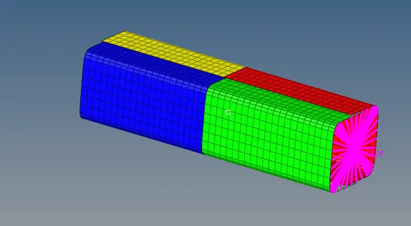
Fig : Crush Tube Model with removed notches
3. Go to Solver-->BCS and delete the rigid body boundary conditions.
4. Run the simulation with Type-7 Recomended Parameters and using Analysis-->Radioss option and Save the input file in new folder and set options and Click Radioss.
5. Change Hypermesh into HyperView and load the Crush_tube.h3d model file and Click Apply.
6. Select the Contour icon and set Result type as Displacement(v), Contact Force(v), Vonmises (s) and click Apply.
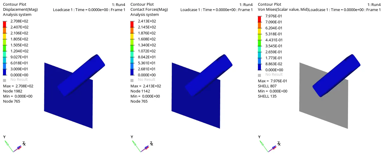
Fig : Displacement Plot Fig : Contact Force Plot Fig : Vonmises Stress plot
7. From the above Contour Plots observed that, Maximum values of Displacement(Strain rate)=2.708E+02, Contact Force = 2.413E+02 N and Vonmises Stress = 7.976E-01 `N/(mm)^2`.
8. After Plotting contour plots, Change HyperView into HyperGraph 2D to plot the Energy as a function of time.
9. Load the time history file Crush_tubeT01 file.
10. Select the Y-type,Y-Request and Y-Component as Global Variables-->Internal Energy, Kinetic Energy,Contact Energy,Total Energy-->Mag and Rigidwallforce-->3wall-->total resultant force and click Apply.
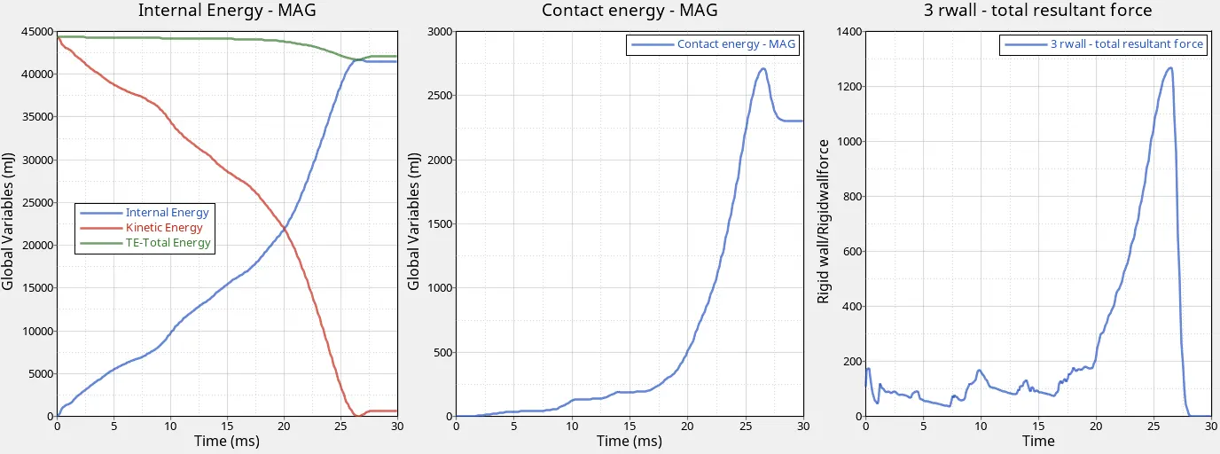
11. From The above plot,
- 42000 mJ is the maximum Internal Energy generated for Impacting the Crash tube on Rigid Wall. After the Element gets fully crashed, Some opposite reaction force will created, due to opposite force some amount of kinetic energy increases and Total Energy is not stable at that time of Opposite reaction happens.
- 2750 mJ is the Maximum Contact energy required to contact occured between Master & Slave Node. After Element reaches the Reference Strain rate, Contact Energy will be decreased to 2250 mJ due to Opposite force applied.
- 1280 N Rigid Wall Force is maximum force. When the material reaches the reference strain rate, at that time rigid wall force will be sudden decrease due to oppsite force happens.
Case-5 : Creating Notch in the middle
1. In case-5, Import the same model Crash_tube_0000.rad file used in Case-4.
2. Creating Notch in the middle for all parts, using Tools-->translate option and select the nodes in the middle and set Screen normal and Magnitude value, after that click translate + or - according to the position of the component.
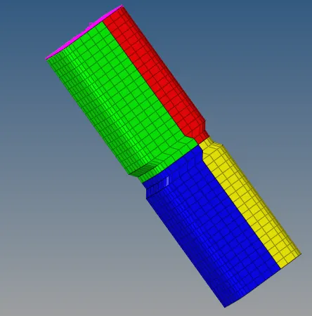
Fig : Crash tube with Notches in middle
3. Run the simulation with Type-7 Recomended Parameters and using Analysis-->Radioss option and Save the input file in new folder and set options and Click Radioss.
4. Change Hypermesh into HyperView and load the Crush_tube.h3d model file and Click Apply.
5. Select the Contour icon and set Result type as Displacement(v), Contact Force(v), Vonmises (s) and click Apply.
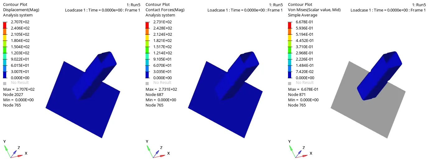
Fig : Displacement Plot Fig : Contact Force Plot Fig : Vonmises Stress plot
6. From the above Contour Plots observed that, Maximum values of Displacement(Strain rate)=2.707E+02, Contact Force = 2.731E+02 N and Vonmises Stress = 6.678E-01 `N/(mm)^2`.
7. After Plotting contour plots, Change HyperView into HyperGraph 2D to plot the Energy as a function of time.
8. Load the time history file Crush_tubeT01 file.
9. Select the Y-type,Y-Request and Y-Component as Global Variables-->Internal Energy, Kinetic Energy,Contact Energy,Total Energy-->Mag and Rigidwallforce-->3wall-->total resultant force and click Apply.
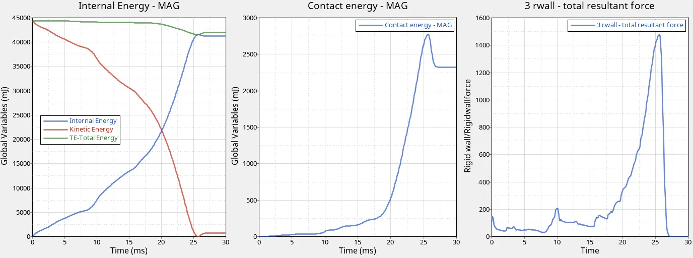
10. From The above plot,
- 42000 mJ is the maximum Internal Energy generated for Impacting the Crash tube on Rigid Wall. After the Element gets fully crashed, Some opposite reaction force will created, due to opposite force some amount of kinetic energy increases and Total Energy is not stable at that time of Opposite reaction happens.
- 2750 mJ is the Maximum Contact energy required to contact occured between Master & Slave Node. After Element reaches the Reference Strain rate, Contact Energy will be decreased to 2250 mJ due to Opposite force applied.
- 1500 N Rigid Wall Force is maximum force. When the material reaches the reference strain rate, at that time rigid wall force will be sudden decrease due to oppsite force happens.
Case-6 : Notch with nodes only from opposing 2 faces
1. In case-6, Import the same model Crash_tube_0000.rad file used in Case-4.
2. Creating Notch with nodes only from opposing 2 faces for all parts, using Tools-->translate option and select the nodes in the middle and set Screen normal and Magnitude value, after that click translate + or - according to the position of the component.
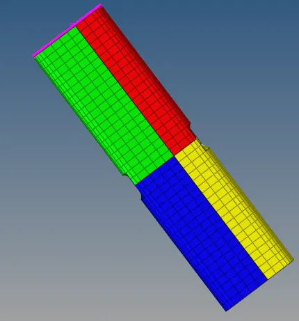
Fig : Crash Tube Model with notches in Opposing 2 faces
3.Run the simulation with Type-7 Recomended Parameters and using Analysis-->Radioss option and Save the input file in new folder and set options and Click Radioss.
4. Change Hypermesh into HyperView and load the Crush_tube.h3d model file and Click Apply.
5. Select the Contour icon and set Result type as Displacement(v), Contact Force(v), Vonmises (s) and click Apply.
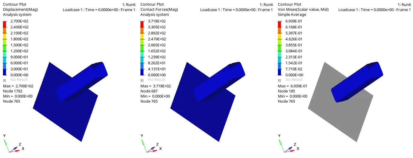
Fig : Displacement Plot Fig : Contact Force Plot Fig : Vonmises Stress plot
6. From the above Contour Plots observed that, Maximum values of Displacement(Strain rate)=2.700E+02, Contact Force = 3.718E+02 N and Vonmises Stress = 6.939E-01 `N/(mm)^2`.
7. After Plotting contour plots, Change HyperView into HyperGraph 2D to plot the Energy as a function of time.
8. Load the time history file Crush_tubeT01 file.
9. Select the Y-type,Y-Request and Y-Component as Global Variables-->Internal Energy, Kinetic Energy,Contact Energy,Total Energy-->Mag and Rigidwallforce-->3wall-->total resultant force and click Apply.
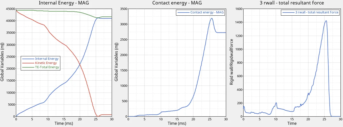
10. From The above plot,
- 42000 mJ is the maximum Internal Energy generated for Impacting the Crash tube on Rigid Wall. After the Element gets fully crashed, Some opposite reaction force will created, due to opposite force some amount of kinetic energy increases and Total Energy is not stable at that time of Opposite reaction happens.
- 3200 mJ is the Maximum Contact energy required to contact occured between Master & Slave Node. After Element reaches the Reference Strain rate, Contact Energy will be decreased to 2750 mJ due to Opposite force applied.
- 1410 N Rigid Wall Force is maximum force. When the material reaches the reference strain rate, at that time rigid wall force will be sudden decrease due to oppsite force happens.
COMPARISON OF CASE-1 & CASE-2 :
Fig : Case-1 & Case-2 : Internal Energy(PART) & Contact Energy
Explanation : By changing Inacti = 0 to Inacti = 6 Initial gap is adjusted (the node is slightly depenetrated).Comparing Case-1 & Case-2 there is no Initial penetration and Same amount of Energy and force is generated.
COMPARISON OF CASE-1 & CASE-3 :
Fig : Case-1 & Case-3 : Internal Energy(PART) & Contact Energy
Explanation : Type-7 Contact is Node to Surface Contact and Type-11 Contact is edge to edge contact. In Case-1 Type-7 Contact is used and in Case-3 both Type-7 & Type-11 Contact is used. Comparing Case-1 & Case-3, Internal Energy, Contact Energy and Rigid Wall Force is high in Case-3 due to Contact force in all elements and deformation occurs early at time=25 ms.
COMPARISON OF CASE-4, CASE-5 & CASE-6 :
Fig : Case-4, Case-5 & Case-6 : Internal Energy(PART) & Contact Energy
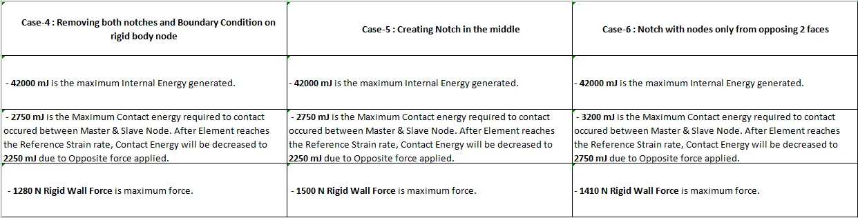
Explanation : By Comparing of Case-4, Case-5 & Case-6,
- Rigid wall force is very less in case-4 due to removal of notches and boundary condition on rigid body node.
- Rigid Wall force is very high in case-5 because sudden impact will happens in the middle due to notches in middle.
- Contact energy is high in case-6 due to high contact force and penetration occurs in the middle because of notch with nodes only from opposing 2 faces.
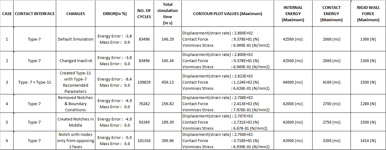
RESULT :
CONCLUSION :
In Study-1 : --> Mesh is created for bumper Assembly with element size 6mm.
In Study-2 : --> By using radioss in Hypermesh, Simulation was run for 6 Cases by changing Contact Interfaces, Boundary Conditions and Notches.
- Case-1 : Default Simulation(Type-7 Contact)
- Case-2 : Changed Inacti=6 in Type-7 Contact Parameters
- Case-3 : Created Type-11 Contact and Type-7 Recomended Properties defined for Type-7 & Type -11
- Case-4 : Removed Notches and Boundary Condition on rigid node body and then run the simulation
- Case-5 : Created Notches in the Middle of the parts
- Case-6 : Created Notch with nodes only from opposing 2 faces.
--> Rigid Wall Force, Contact Energy and Internal Energy Results were plotted and results were compared between Case-1&2, Case-1&3 and Case-4,5 &6.