Assignment 5
AIM: To create the mesh for bumper assembly and to study the different case in hypercrash based on interface concept and plot the results.
KEYWORDS: Interface, Node, Penalty, Master node, Slave node, Gap, Penetration, Scale factor, Stiffness, Strain, Resistive force.
SOFTWARE: Hypermesh -> Hypercrash
OBJECTIVE:
- To Mesh the bumper as per quality criteria.
- Run the crash tube model as it is.
- Change the Inacti=6 and run.
- Create the type 11 contact and run.
- Remove both notches and remove boundary condition on rigid body node then run.
- Create a new notch in the middle ,select the whole section and run.
- Create a new notch with nodes only from opposing 2 faces and run.
- Compare the results from all cases (2 - 7).
INTRODUCTION:
To find deformation, stress, and energy absorbing capacity of various structural components of a vehicle hitting a stationary or moving object. The component is said to be crashworthy (safe) if it meets the plastic strain and energy targets. Bumper is one of the components which is used to protect passengers from front and rear collision. Bumper crash tests are necessary for instance to calculate the energy absorption of this component during a crash. For crash analysis the preferred element type is hexa over tetra when using 3D elements, shell elements are used for 2D modeling (as in the case of this analysis). Follow the mesh flow line requirement and avoid rotating quads, or diamond element formation. Constant mesh size is preferred over variable mesh size. Initially for the given Bumper model mesh as been applied (Shell 3N & Shell 4N) with element size of 6mm. After the mesh, Seam weld is performed which defines the connectivity and indicated in yellow colour in the Figure 1.
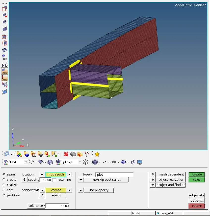
Figure_1: Mesh and Seam weld of Bumper model
Here, The Simulation of all 6 cases mainly based on the Interface for the Crash Tube (Figure 2) , how parts interact when they come into contact with each other and it includes penalty method, Type 7 (Node-Surface Interface), type 11 (Edge-Edge Interface).
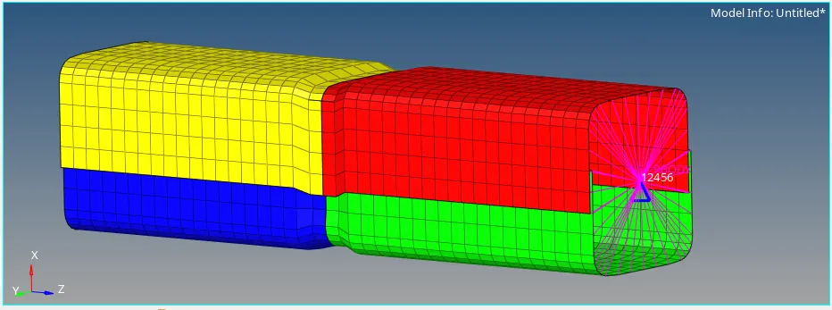
Figure_2: Crash tube Model
Penalty Method: The Penalty method treats the behaviour between Slave node and master segments as springs that generates resistive force as a function of penetration.
Spring elements are created between the slave node and its projection. The spring stiffness is automatically computed according to the material and property of both master segment and slave node.
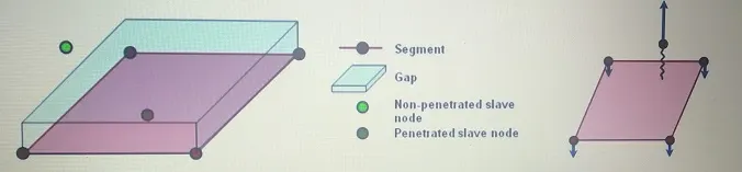
Figure_3: Penalty Method
Type_7 (Nodes to Surface):
- General purpose interface can simulate all types of impact between a set of nodes and a Master surface.
- Non-oriented and slave nodes can belong to the master surface hence auto impact possible.
- Automatic node to surface contact interface using penalty method with variable stiffness.
- A gap is defined around the master segment and the slave nodes.
- The contact gap can be constant or variable.
- Resistive forces are applied to keep slave nodes out of the contact gap.
- Interface time step is computed to inverse stability.
- The energy jumps induced by a node impacting from the shell edges are removed by the use of a cylindrical gap around the edges.
- The main advantage of interface type7 is that the stiffness is not constant and increase with the penetration preventing the node from going through the shell mid-surface.
- The gap used is on both sides of the shell mid-surface and a cylindrical gap is added around the edges.
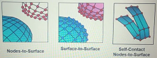
Figure_4: Types of Interface
Type_11 (Edge to Edge interface):
- In the case of edges crossing, type 11 interface can be added to capture the physic correctly.
- Type11 is defined by identifying master and slave lines (edges).
- Type 11 works similar to type 7 interms of
- Penalty method
- Gap defination
- Search method
Important Interface Parameters:
Igap -> Determines how the size of the gap is calculated.
Gap_min -> Minimum gap for activation of interface.
Inacti -> Action to take if initial penetration exist.
Istf -> Affects how the stiffness of the interface is calculated.
Iform -> Friction formulation
St_min -> Minimum stiffness to use in the interface.
Idel -> What to do with slave nodes and master segments if elements fails (deleted) that they are attached to.
For all the 6 cases, the simulation as been carried out on the Crash tube model which as defined property and the material used as Steel (Fig-5). Law2_Johnson_cook solver is used because the model is going to large deformation with a velocity of 13.3 m/s towards translational (Rigid wall). Law2 defines that there is elastic deformation initially and crosses the yield point as plastic region (permanent deformation). Mainly it is used to reduce the energy error where there is neligible hourglass energy and also stress formed on the material is optimal.
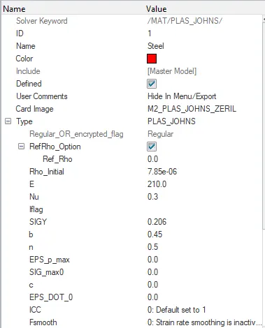
Figure_5: Steel Property
The shell elements is differed by shell thickness which as 2mm and 3mm as shown in the below Figure 6 & 7 respectively. The Number of Intergration is 5 and the Ishell is 24:QEPH shell formulati -on which gives better results moreover the mesh is fine enough so highly recommended.
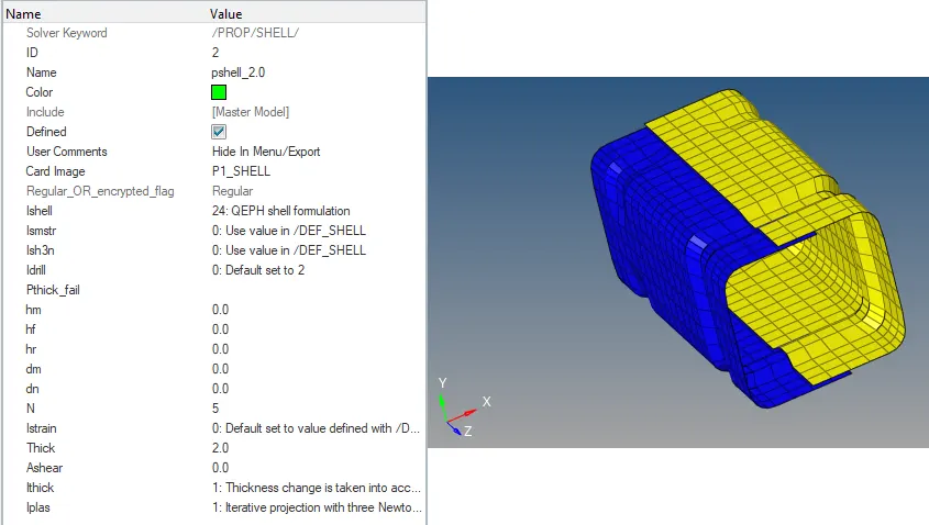
Figure_6: 2mm Shell thickness
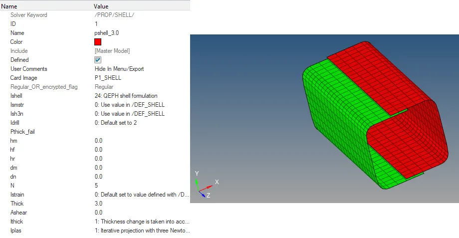
Figure_7: 3mm Shell thickness
CASE_1_DEFAULT:
In this case, the default model is imported and run the simulation with that properties where as the notch is created on the 2mm shell thickness. Type 7 interface contact is used with default property as shown in the Figure 8.
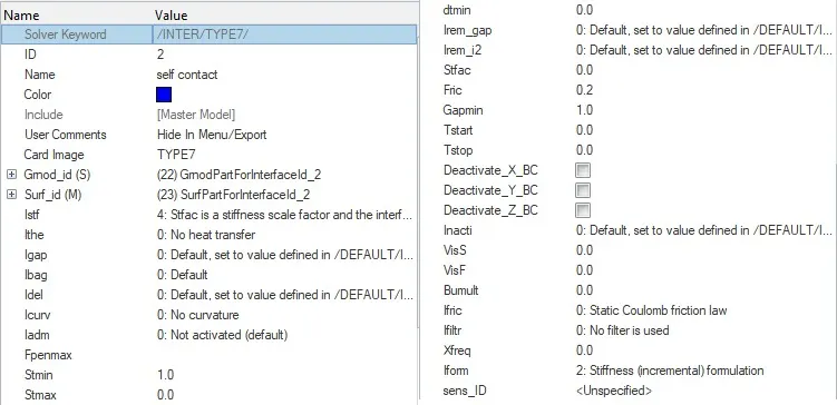
Figure_8: Type 7 interface property
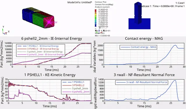
Figure_9: Case1 simulation results
For this simulation, the max contact force is created as 93.82 N where as the time history (TH) for all the components are created inorder to study the deformation and energy variation in each component wrt to time.
The Internal energy for the 2mm shell components is increasing at the begining because it is attached to the rigid wall and deform smoothly at the notch area where as the stiffness is less at this parts. The Internal energy for the 3mm shell components is zero for 10ms and linearly increasing to deform (compression takes place) at a velocity 13.3 m/s and the stiffness is high for this parts because of flat surface area . The end of this components defines the rigidity with a translational (z-direction) degree of freedom.
The Kinetic energy for the 2mm shell components is varying at the begining for 10ms and maintained as constant which means no more deformation occurs. Because of Notch area presents over the components it deforms very quickly. The Kinetic energy for the 3mm shell components is continously varying over the time 25ms means deformation takes place (compression) at a velocity of 13.3 m/s.
The contact energy is varying at a very small amount at the beginning and there is a sudden peak formed because there is large amount of energy developed at the end of deformation. The overall elements are became compressed which will develope large force on the rigid wall around 1400 Newton and energy created as 2 kJ.
CASE_2: (Type 7 Recommended Properties)
In this case, the model is imported and run the simulation with recommended properties where as the notch is presented on the 2mm shell thickness. The Type 7 contact interface is used with recommended property as shown in the Figure 10.
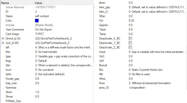
Figure_10: Type 7 recommended properties
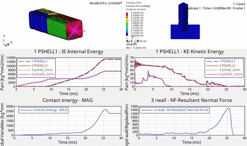
Figure_11: Case2 simulation results
For this simulation, the max contact force is created as 303.3 N where as the time history (TH) for all the components are created inorder to study the deformation and energy variation in each component wrt to time.
The Internal energy for the 2mm shell components is increasing at the begining because it is attached to the rigid wall and deform smoothly from the notch area where as the stiffness is less at this parts. The Internal energy for the 3mm shell components is zero for 10ms and linearly increasing to deform (compression takes place) at a velocity 13.3 m/s and the stiffness is high for this parts because of flat surface area. The end of this components defines the rigidity with a translational (z-direction) degree of freedom.
The Kinetic energy for the 2mm shell components is varying at the begining for 10ms and maintained as constant which means no more deformation occurs. Because of Notch area presents over the components it deforms very quickly. The Kinetic energy for the 3mm shell components is continously varying over the time 25ms means deformation takes place (compression) at a velocity of 13.3 m/s.
The contact energy is varying at a very small amount at the beginning and there is a sudden peak formed because there is large amount of energy developed at the end of deformation. The overall elements are became overlapped or compressed which will develope large force on the rigid wall around 1500 Newton and energy created as 2.5 kJ.
CASE_3: (Type 11 Recommended Properties)
In this case, the model is imported and run the simulation with recommended properties where as the notch is presented on the 2mm shell thickness. The Type 11 contact interface is used with recommended property as shown in the Figure 12.
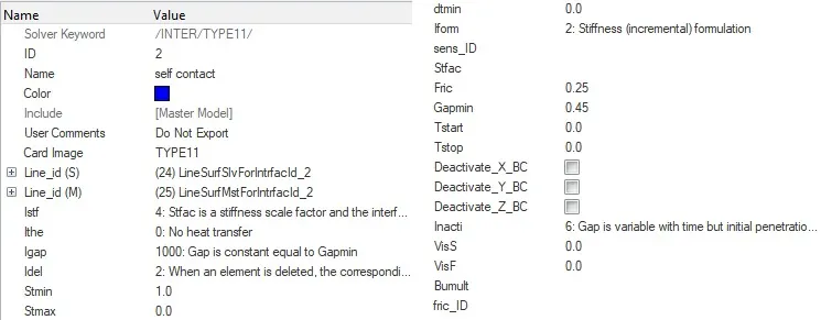
Figure_12: Type 11 recommended properties
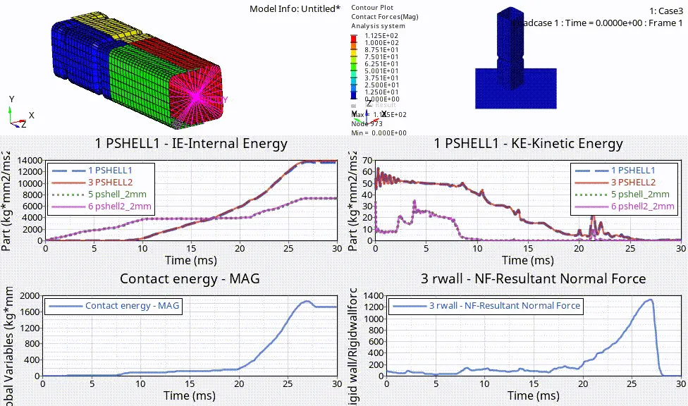
Figure 13: Case3 simulation results
For this simulation, the max contact force is created as 112.5 N where as the time history (TH) for all the components are created inorder to study the deformation and energy variation in each component wrt to time.
The Internal energy for the 2mm shell components is increasing at the begining because it is attached to the rigid wall and deform smoothly from the notch area where as the stiffness is less at this parts. The Internal energy for the 3mm shell components is zero for 10ms and linearly increasing to deform (compression takes place) at a velocity 13.3 m/s and the stiffness is high for this parts because of flat surface area. The end of this components defines the rigidity with a translational (z-direction) degree of freedom.
The Kinetic energy for the 2mm shell components is varying at the begining for 10ms and maintained as constant which means no more deformation occurs. Because of Notch area presents over the components it deforms very quickly. The Kinetic energy for the 3mm shell components is continously varying over the time 25ms means deformation takes place (compression) at a velocity of 13.3 m/s.
The contact energy is varying at a very small amount at the beginning and there is a sudden peak formed because there is large amount of energy developed at the end of deformation. The overall elements are became overlapped or compressed which will develope large force on the rigid wall around 1300 Newton and energy created as 1.7 kJ.
CASE_4: (No Notch & No BC's)
In this case, the model is imported and run the simulation with recommended properties where there is notch is presented on the 2mm shell thickness and also the boundary conditions are removed. The Type 11 contact interface is used with recommended property as shown in the Figure 12.
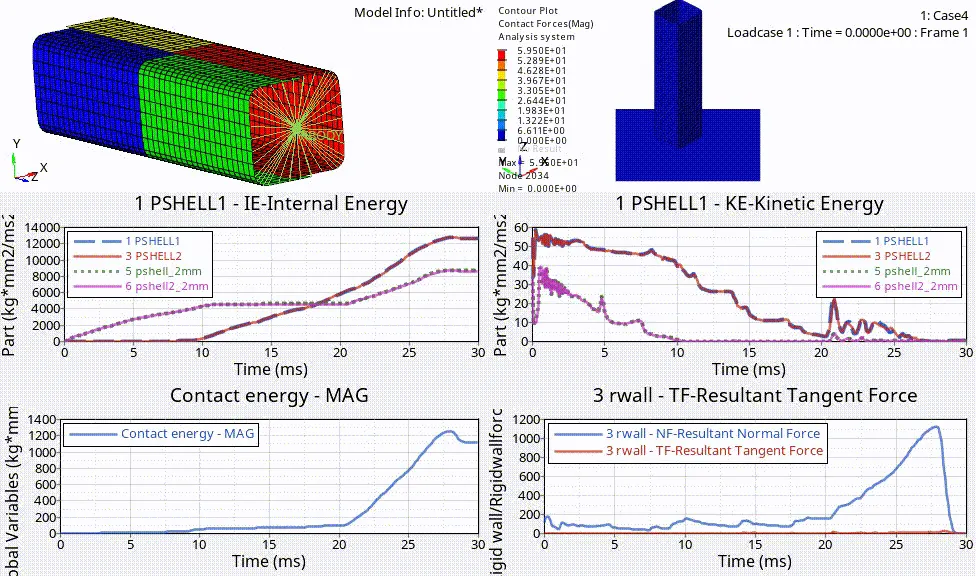
Figure 14: Case4 simulation results
For this simulation, the max contact force is created as 59.5 N where as the time history (TH) for all the components are created inorder to study the deformation and energy variation in each component wrt to time.
The Internal energy for the 2mm shell components is increasing at the begining because it is attached to the rigid wall and deform smoothly there is no notch area where as the stiffness is constant over all the model. The Internal energy for the 3mm shell components is zero for 10ms and linearly increasing to deform (compression takes place) at a velocity 13.3 m/s. The end of this components defines the rigidity with a translational (z-direction) degree of freedom. The Total energy for all the 4 components are varying individually with absence of boundary conditions.
The Kinetic energy for the 2mm shell components is varying at the begining for 10ms and maintained as constant which means no more deformation occurs. Because of Notch area presents over the components it deforms very quickly. The Kinetic energy for the 3mm shell components is continously varying over the time 25ms means deformation takes place (compression) at a velocity of 13.3 m/s.
The contact energy is varying at a very small amount at the beginning and there is a sudden peak formed because there is large amount of energy developed at the end of deformation. The overall elements are became overlapped or compressed which will develope large force on the rigid wall around 1100 Newton and energy created as 1.3 kJ.
CASE_5: (Mid Notch & No BC's)
In this case, the model is imported and run the simulation with recommended properties where there is Notch presented on the middle surface and also the boundary conditions are removed. The Notch is created with the magnitude or depth of 3mm. The Type 11 contact interface is used with recommended property as shown in the Figure 12.
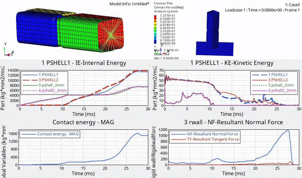
Figure 15: Case5 simulation results
For this simulation, the max contact force is created as 73.17 N where as the time history (TH) for all the components are created inorder to study the deformation and energy variation in each component wrt to time.
The Internal energy for the 2mm shell components is increasing at the begining because it is attached to the rigid wall and deform smoothly there is notch on the middle surface where as the stiffness is less. The Internal energy for the 3mm shell components is zero for 10ms and linearly increasing to deform (compression takes place) at a velocity 13.3 m/s. The end of this components defines the rigidity with a translational (z-direction) degree of freedom. The Total energy for all the 4 components are varying individually with absence of boundary conditions.
The Kinetic energy for the 2mm shell components is varying at the begining for 10ms and maintained as constant which means no more deformation occurs. Because of no Notch presents over the components it deforms constantly. The Kinetic energy for the 3mm shell components is continously varying over the time 25ms means deformation takes place (compression) at a velocity of 13.3 m/s.
The contact energy is varying at a very small amount at the beginning and there is a sudden peak formed because there is large amount of energy developed at the end of deformation. The overall elements are became overlapped or compressed which will develope large force on the rigid wall around 1100 Newton and energy created as 1.3 kJ.
CASE_6: (Opp. 2 Mid Notch & No BC's)
In this case, the model is imported and run the simulation with recommended properties where there is Notch presented on the oppsite of 2 face on the Model middle surface and also the boundary conditions are removed. The Notch is created with the magnitude or depth of 3mm. The Type 11 contact interface is used with recommended property as shown in the Figure 12.
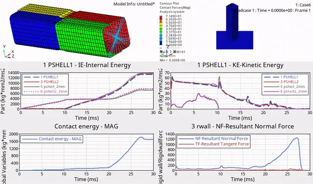
Figure 16: Case6 simulation results
For this simulation, the max contact force is created as 71.49 N where as the time history (TH) for all the components are created inorder to study the deformation and energy variation in each component wrt to time.
The Internal energy for the 2mm shell components is increasing at the begining because it is attached to the rigid wall and deform smoothly there is notch on the middle opposite 2 surface where as the stiffness is less. The Internal energy for the 3mm shell components is zero for 10ms and linearly increasing to deform (compression takes place) at a velocity 13.3 m/s. The end of this components defines the rigidity with a translational (z-direction) degree of freedom. The Total energy for all the 4 components are varying individually with absence of boundary conditions.
The Kinetic energy for the 2mm shell components is varying at the begining for 10ms and maintained as constant which means no more deformation occurs. Because of Notch area presents over the components it deforms very quickly. The Kinetic energy for the 3mm shell components is continously varying over the time 25ms means deformation takes place (compression) at a velocity of 13.3 m/s.
When objects collide, contact forces transfer energy so as to change the objects' motions. When two objects interact, each one exerts a force on the other, and these forces can transfer energy between them. Fields contain energy that depends on the arrangement of the objects in the field.
The contact energy is varying at a very small amount at the beginning and there is a sudden peak formed because there is large amount of energy developed at the end of deformation. The overall elements are became overlapped or compressed which will develope large force on the rigid wall around 1300 Newton and energy created as 1.7 kJ.
RESULTS:
Comparing Case1 & Case2:
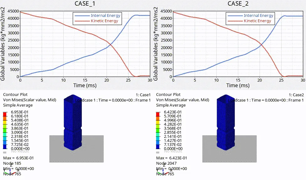
Figure 17: Energy comparision for case1 & case2
By comparing Case1 & Case2, the Energy variation is almost similar because of Type 7 interface where as there is change in stress formation 0.695 Mpa for case1 and 0.6423 Mpa for case2 due to change in type 7 property (Figure 10) in case2.
Comparing Case2 & Case3:
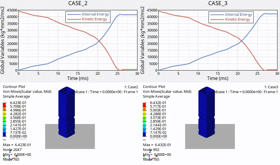
Figure 18: Energy comparision for case2 & case3
By comparing Case2 & Case3, the Energy variation is plotted of Type 7 interface for case2 and type 11 interface for case3. The energy disspation in case 3 is large than case2 and also there is small change in stress formation 0.6423 Mpa for case2 and 0.6432 Mpa for case3 due to change in change in Interface with recommended properties (Figure 10 & 12).
Comparing Case4, Case5 & Case6:
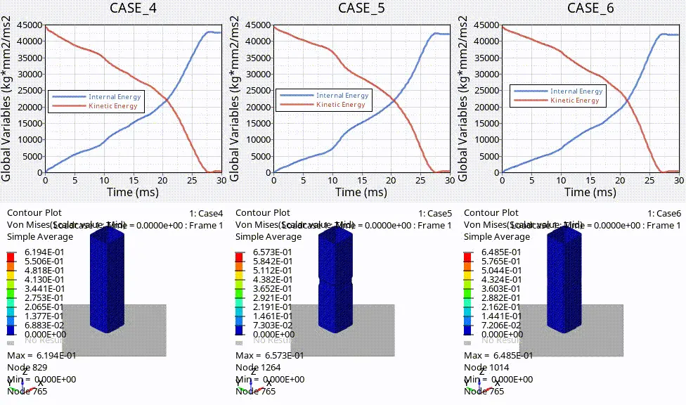
Figure 19: Energy comparision for case4, case5 & case6
By comparing Case4, Case5 & Case6, the Energy variation is almost similar because of Type 11 interface where as there is change in stress formation 0.6195 Mpa for case4 , 0.657 Mpa for case5 and 0.6485 Mpa for case6 due to Notch created and absence of boundary conditions.
CONCLUSION:
The Bumper model as been meshed and welded (seam) with the element size of 6mm.
All the 6 cases as simulated based on the conditions and compared the results as shown in the chart.

By comparing type 7 and type 11 with recommended properties, the energy error is less in type 11 interface but the stress formation is less in Type 7 interface.
Types of contact interface is used based on the particular condition.
Drive_Link:
https://drive.google.com/drive/folders/1l_Pd-W2Yo3Bc5tUvCNc4t1prgt0LEoNW?usp=sharing