Assignment 4
AIM:To make an analysis of rupture plate having 7 different criterion of material card having there own and different results along with making the conclusion by differentiating it seperately.
PROCEDURE:The following rupture plate has following different conditions to which we gotta go one by one,steps are as follows:
CASE 1: In the very first question it is being asked to run the model and saving it to a given name stated above.
ANS:We first import the model then running the simulation using RADIOS in ANALYSIS mode but before that we check the material properties and the shell properties which is by default stated below:
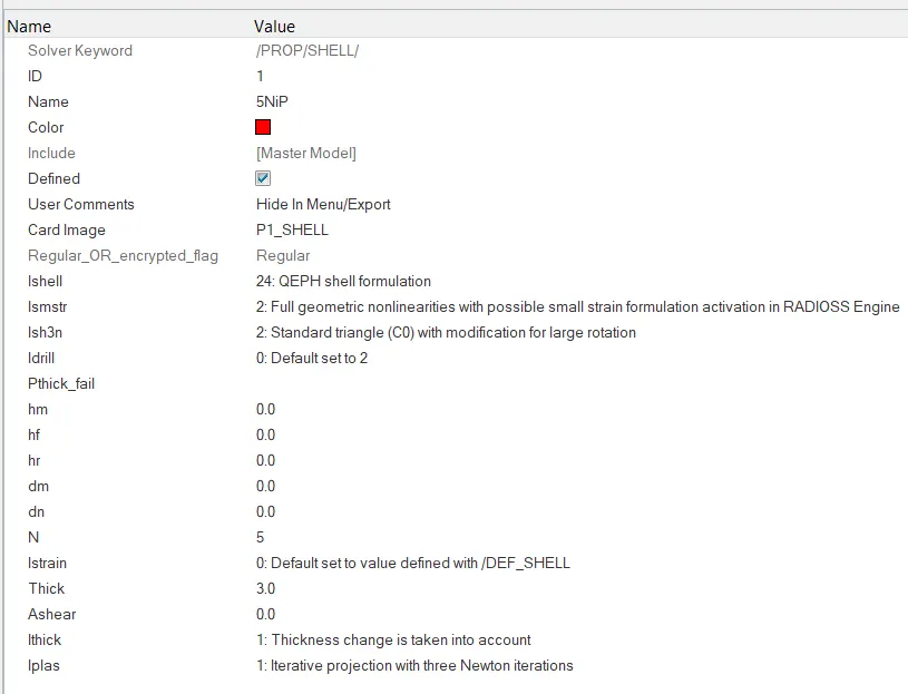
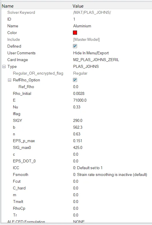
Saving the model as per the name suggest above and then apply the simulation to it.

Now opening/loading to h3d file in hyperview after running the simulation what we have got shown below:
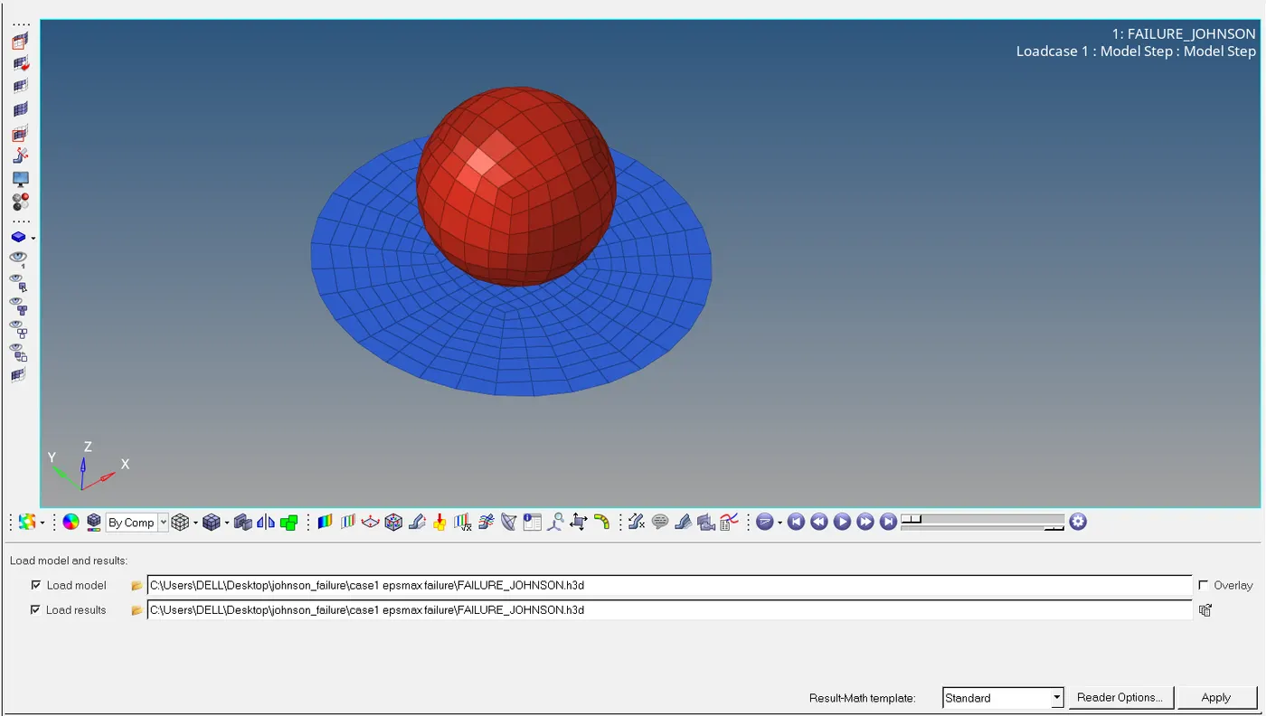
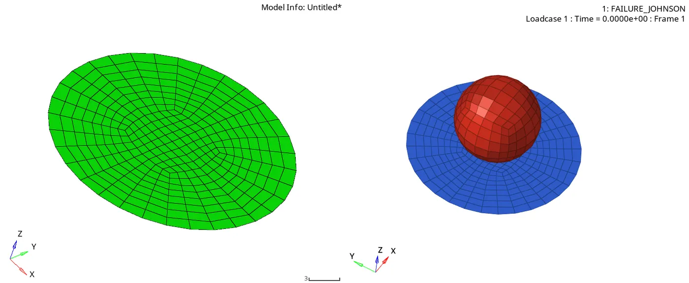
After running the radios we have got 0001 rad out file in which we have the different energy error,mass error ,elapsed time,total no. of cycle it can be said that this rad file is a animation file.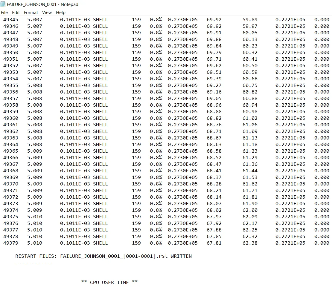
In hyperview we have some run of the rupture plate,in the contour mode animation shown for displacement and von mises stress in which it can be easily seen that after some time of run elements gets deleted in the plate section after getting an rupture .Picture depicts below shows the details of them:
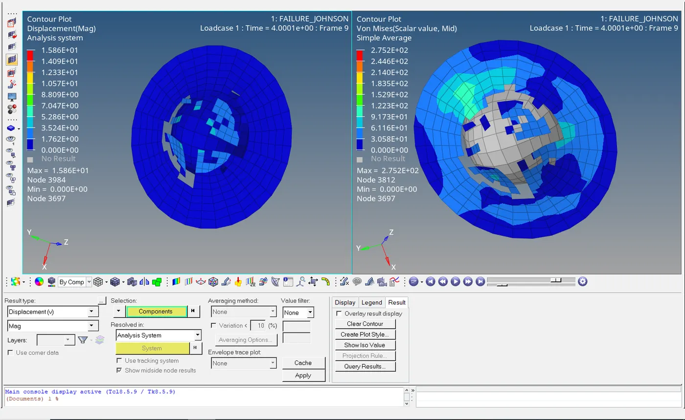
the only changes is done in the averaging method for vonmises stress where simple has been used rather than none.So from this maximum stress is taken 275.2MPA and max.displacement is 1.586E+01mm.
After doing such things we got reached to various answers are:
TOTAL NO.OF CYCLES:49380;
ELAPSED TIME:111.89sec;
ENERGY ERROR(THROUGH OUT CONSTANT)=0.8%
MASS ERROR=0%
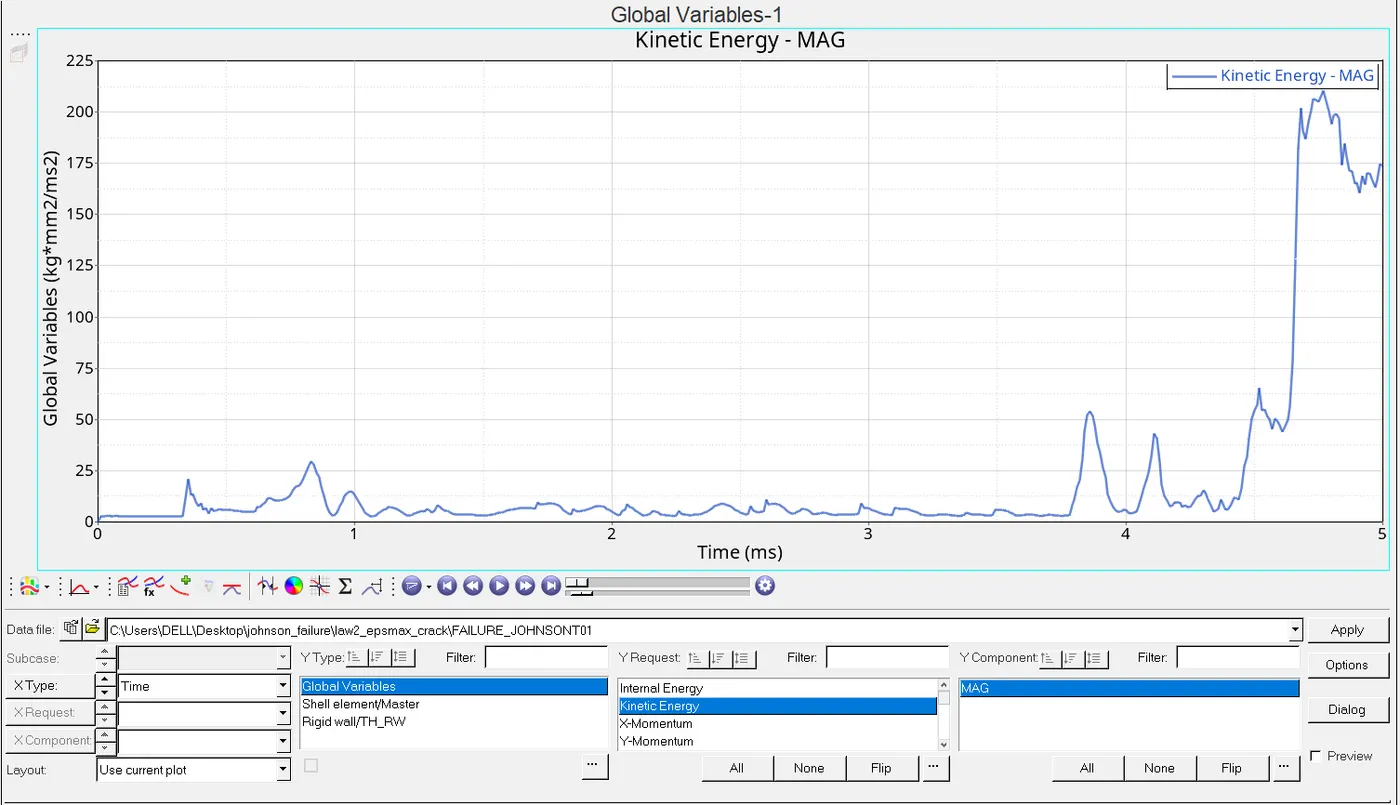
Now shifting the mode towards the hypergraph 2D in order to get a graphical variations in the different energies We gotta upload a T01 file and then we further proceed to the graphs shown below:
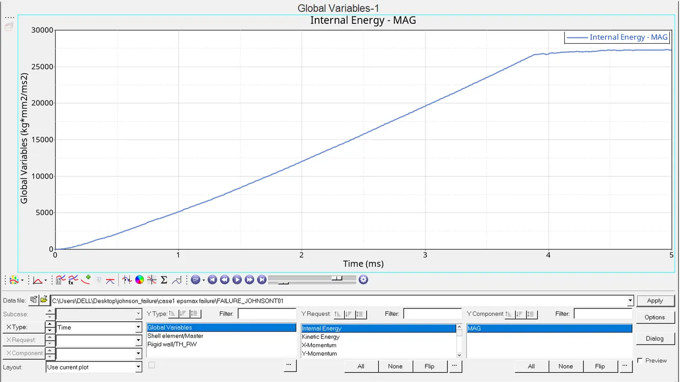
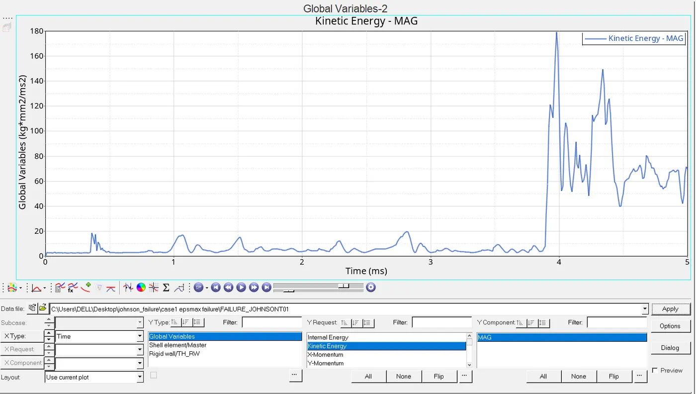
Sudden peak in KE gives the information that there is abruptly elements gets deleted.
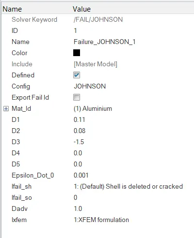
CASE2:In this we gotta make some changes in the johnson rad file like lfail_sh=1,Dadv=1,lxfem=1 which is stated above in the question and then we gotta run the simulation again and observe that what could be the difference in the previous and this case.
Now in hyperview in contour mode we are going to see the displacement and von mises model in order to get the variations we have got to the previous result:
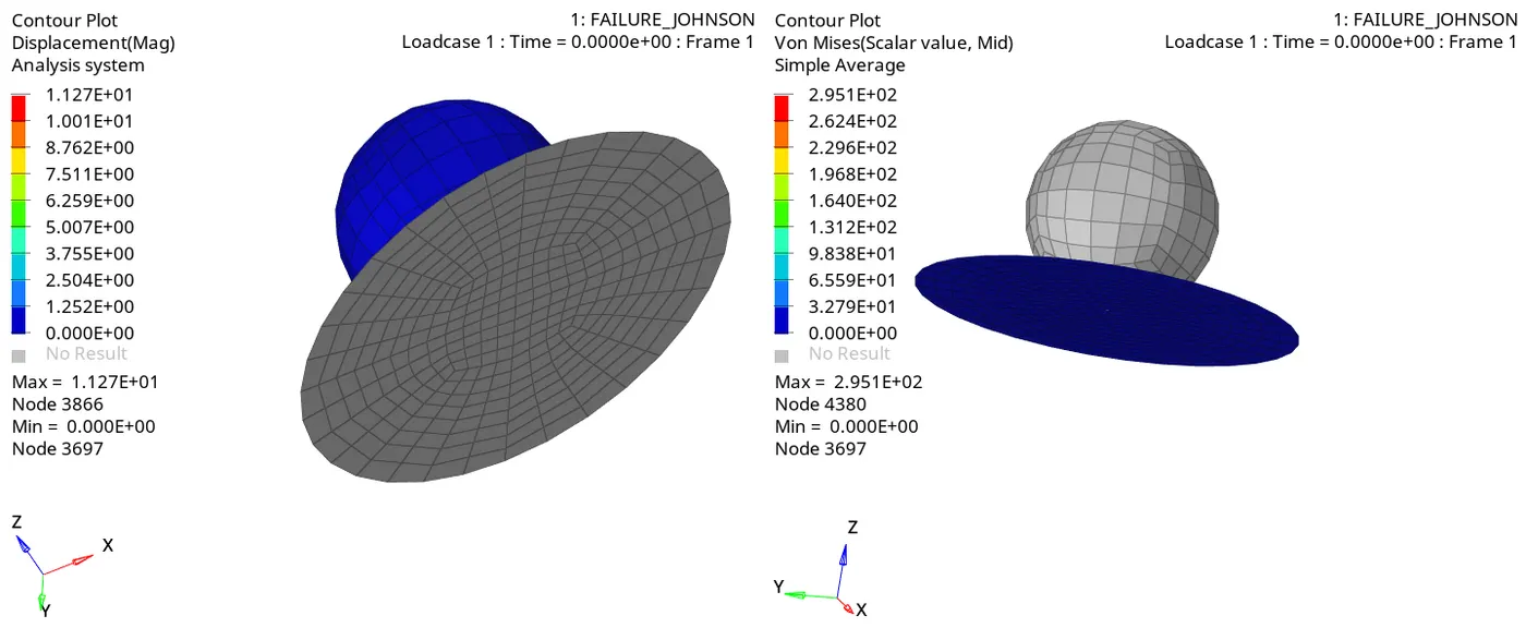
Here we can see the maximum stress is295.1MPA and maximum displacement is 1.127E+01.
Now the out Rad file of 0001 we have got from the new simulation are shown below, which tells us about the what the variation could be possible in order to change the value which is being asked.
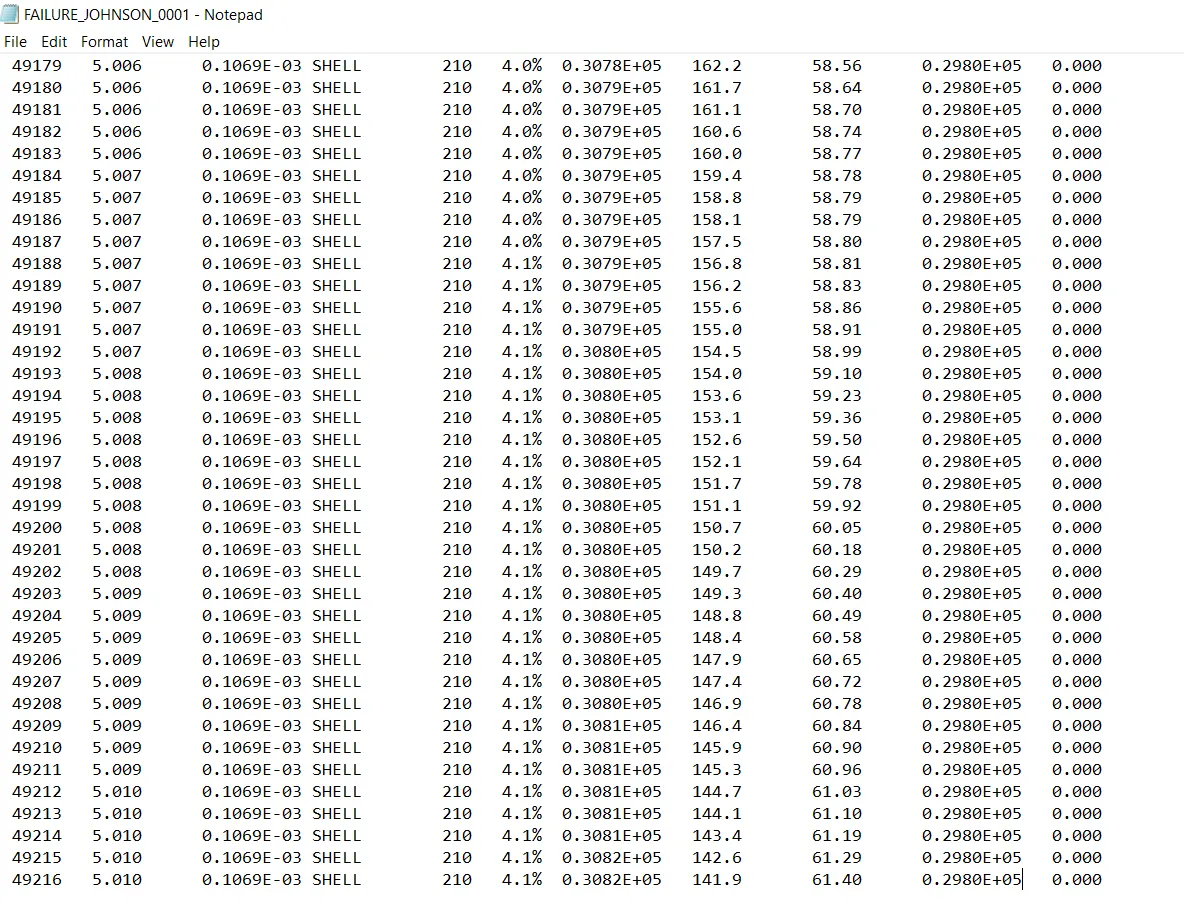
From this we have the certain things are :
Maximum energy error= 4.1%
ELAPSED TIME=93.12sec
MASS ERROR=0%
TOTAL NO.OF CYCLE=49217
In this we have seen lots of variation or it can easily be said that every parameters which is being taken have got some variations except mass error which is constant in either of the parts.
Shifting the mode towards the hypergraph 2D to get energies graphical view shown below:
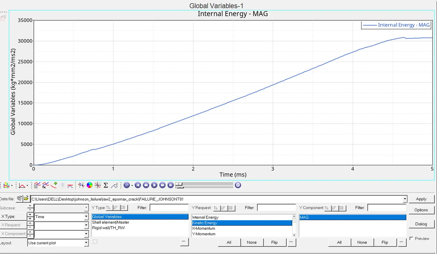
CASE 3:In this we have to first delete the fail johnson card and then naming the new simulation to law2_epsmax_nofail under analysis mode after giving Radios our new simulation have got completed then we have to examined the information that we are getting through this.In the model section we got a name called failures under it we have johnson failure card which we gotta delete before going to simulation.

After simulation gets completed we have to change the mode to hyperview to load a h3d file of the changed part ,what we have got shown below:
For that let us first shift the mode to contour mode and let us see the displacement and von mises stress results shows the rupture of plate.
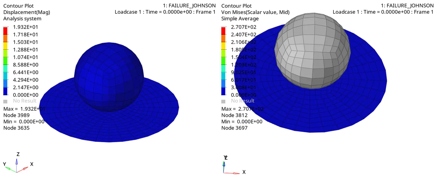
As it is known while using vonmises we prefer simple under averaging method but it is not mandatory we can use none as well.
So from above maximum dispacement is 1.932E+01mm and von mises stress is 270.7N/mm^2 or 270.2 MPA.
Then let us look the rad out file of 0001 of the changed part is shown below.
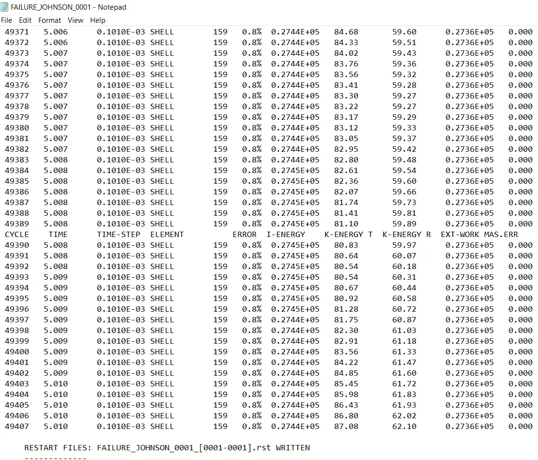
Likewise we some criterion got from it with different values stated below:
ELAPSED TIME=112.27sec
TOTAL NO. OF CYCLES=49408
ENERGY ERROR(CONSTANT)=0.8%
MASS ERROR=0%
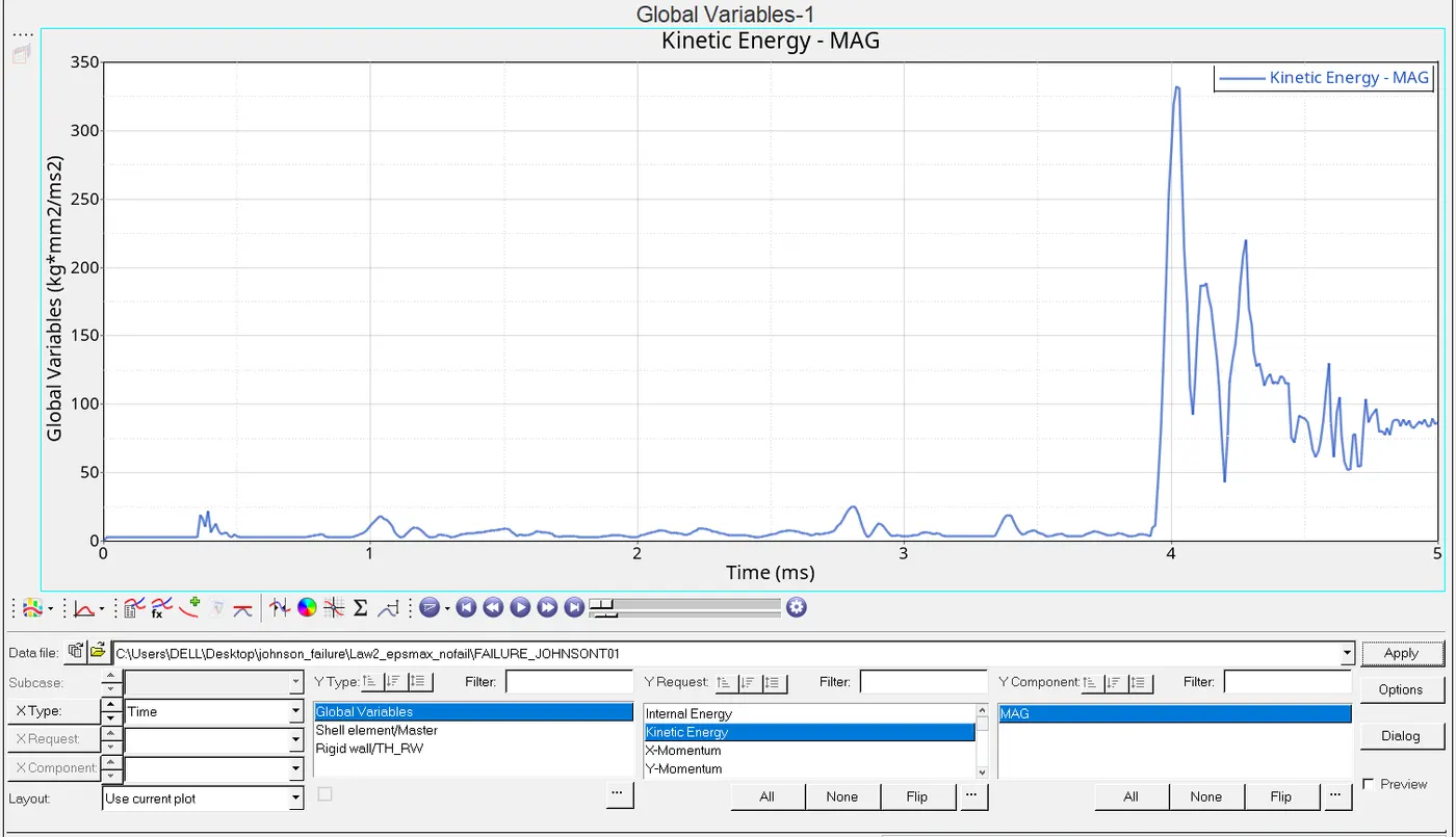
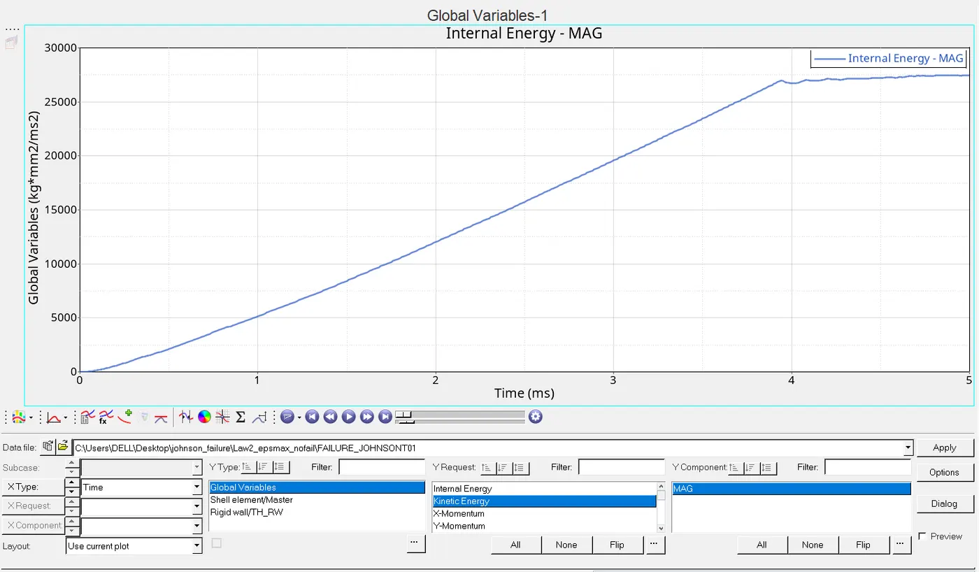
Again shifting the mode to hypergraph 2D such that to get a graphical overview of the rupture plate of new modification energy graphical representation shown below:
First of all loading a T01 file to get respective result
CASE4:In this we have to delete the value of EPS_P_max and saving the simulation to name called law2 and again under the analysis we have Radios is for the simulation we gotta proceed with this.
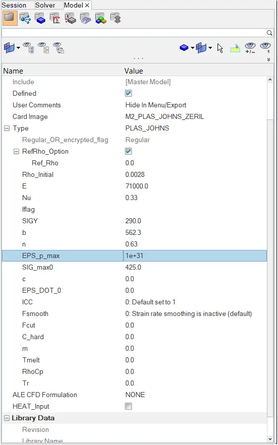
Simulation image shown below:

After execution of simulation we gotta shift the mode to hyperview and in the contour mode we see some animation like displacement and vonmises stress.
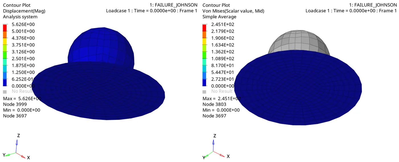
since we have deleted the EPS_p_max,element is not being deleted from the plate it is just showing the rupture in it.In the contour plot the maximum diplacement occured is 5.626E+00 and the max. von mises stress is 245MPA.
Now let us take a look to the rad file of 0001 of it acquire a more information like energies and cycle time etc stated below:
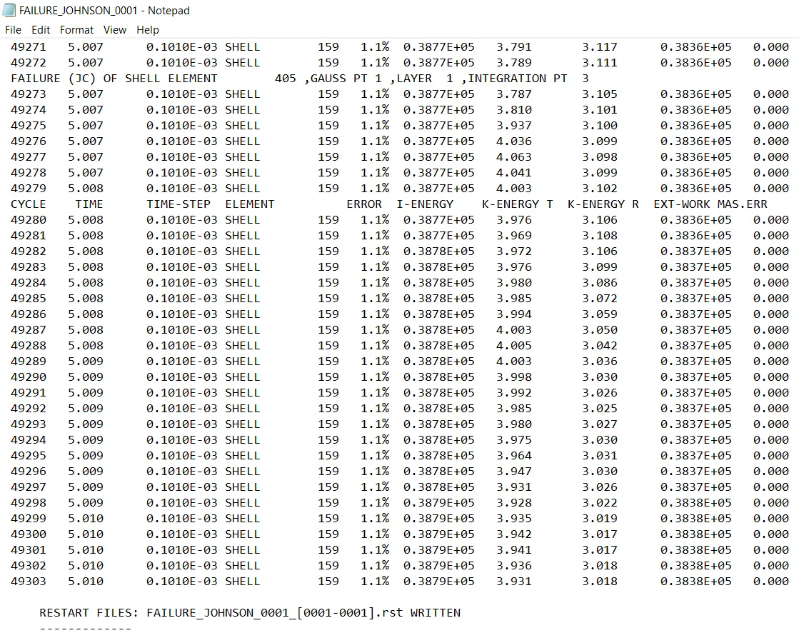
ELAPSED TIME=83.24sec
TOTAL NO. OF CYCLE=49304
ENERGY ERROR=1.1%
MASS ERROR=0%
Now shifting the mode to the hypergraphs 2D to get a graphical view of energies of changes values.
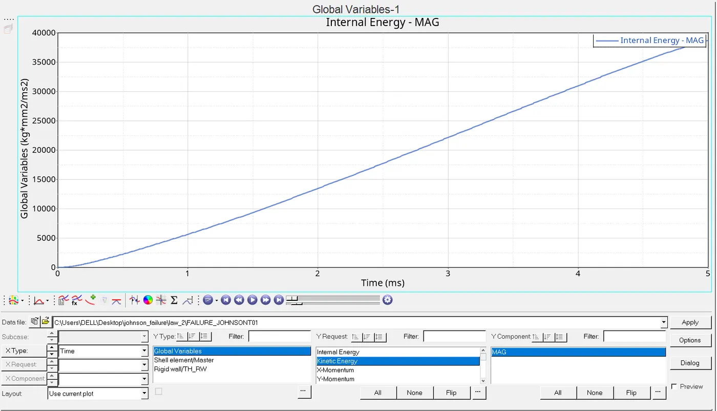
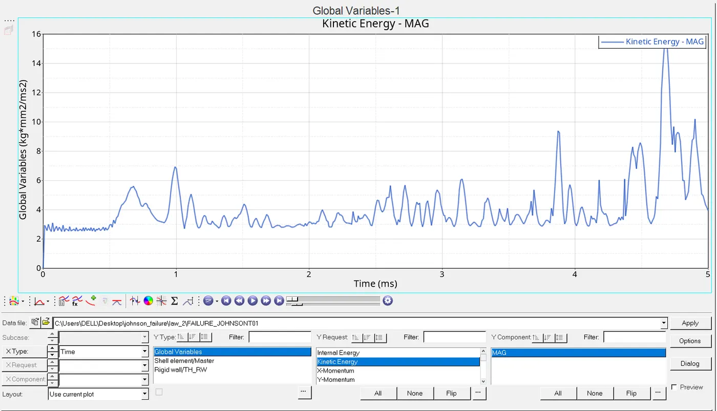
CASE5:As per the question says that material card has to get changed with the same values that was being provided to default values of default material card,material card has to converted into istropic elasticity,new material card are shown below:
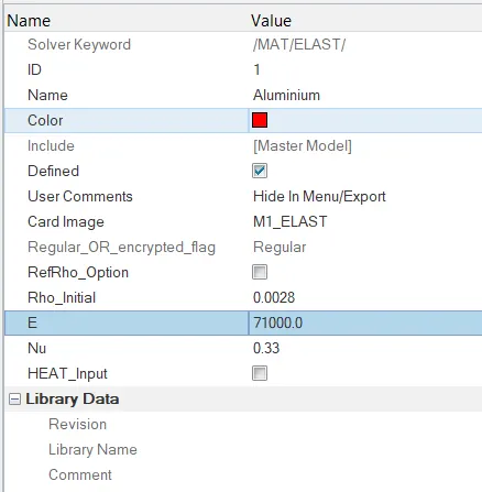
After making changes we run the simulation in analysis called Radios and saving it to law1 as per the question says.

After completion of simulation shifting the mode to hyperview and in the contour mode we see some criterion of animation like for displacement and vonmises stress shown below:
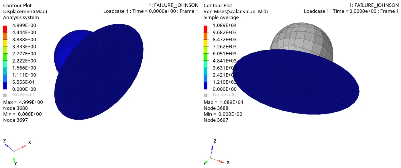
Here the maximum displacement is 4.999E+00mm and the maximum von mises stress is 108.9MPA here it is visible that there is no rupture of plate but it has elasticity in the plate since this is not getting rupture we can say there is only a elastic deformation takes place which follows the hook's law.
Now again we move to the new rad file with the new criterion ,file shown below: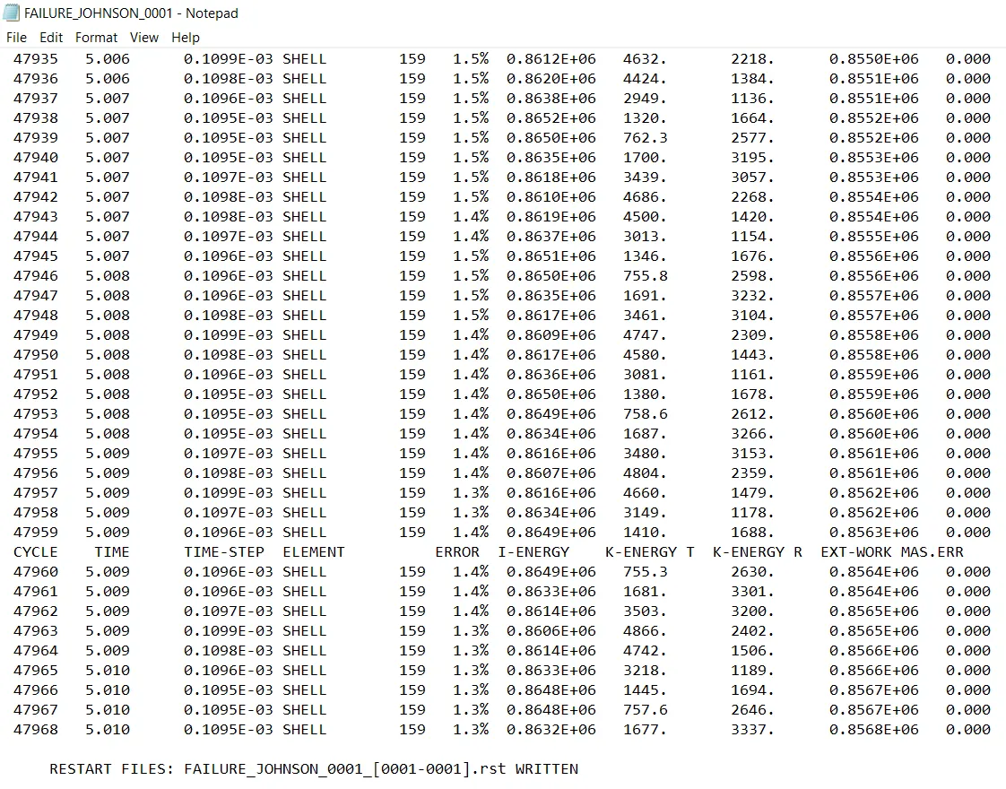
By this chart we got some values and the error ranges stated below:
ELAPSED TIME:107.77sec
TOTAL NO.OF CYCLE=47969
MASS ERROR=0%
ENERGY ERROR(VARYING)=1.3%
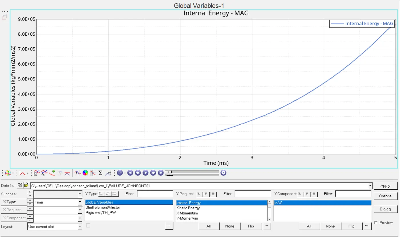
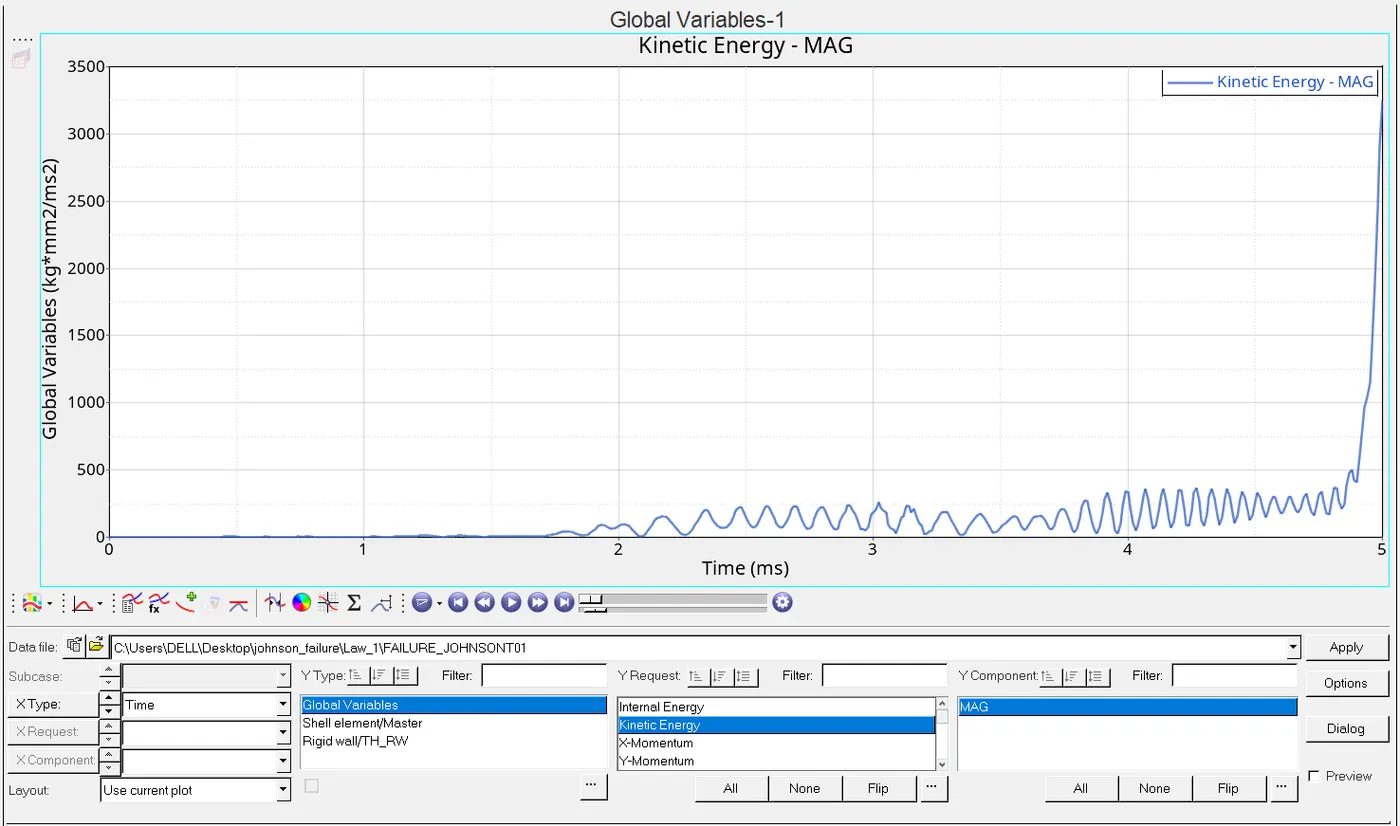
Now shifting the mode to hypergraph 2D to get visualisation of energy and we have to load the T01 file finally representation are shown below:
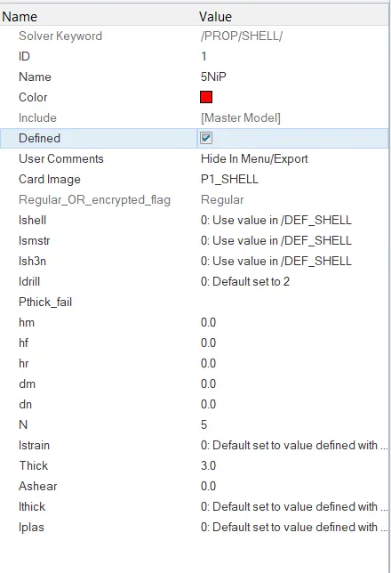
Case6:Here we have to use law27 rad file and follow the simulation as what we had done for johnson failure in above 6 cases,the procedure are similar in which import law27 file and in analysis under it we have radios which gives the simulation before we have the properties of shell and material properties shown below:
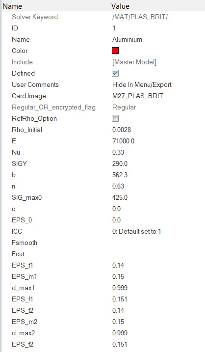

After saving it to a respective name we execute the simulation after completion of it we change the mode to hyperview to in order to get the rupture plate animation ,for that we move to contour mode and take a look towards the displacement and vonmises stress criterion of plate which is shown below:
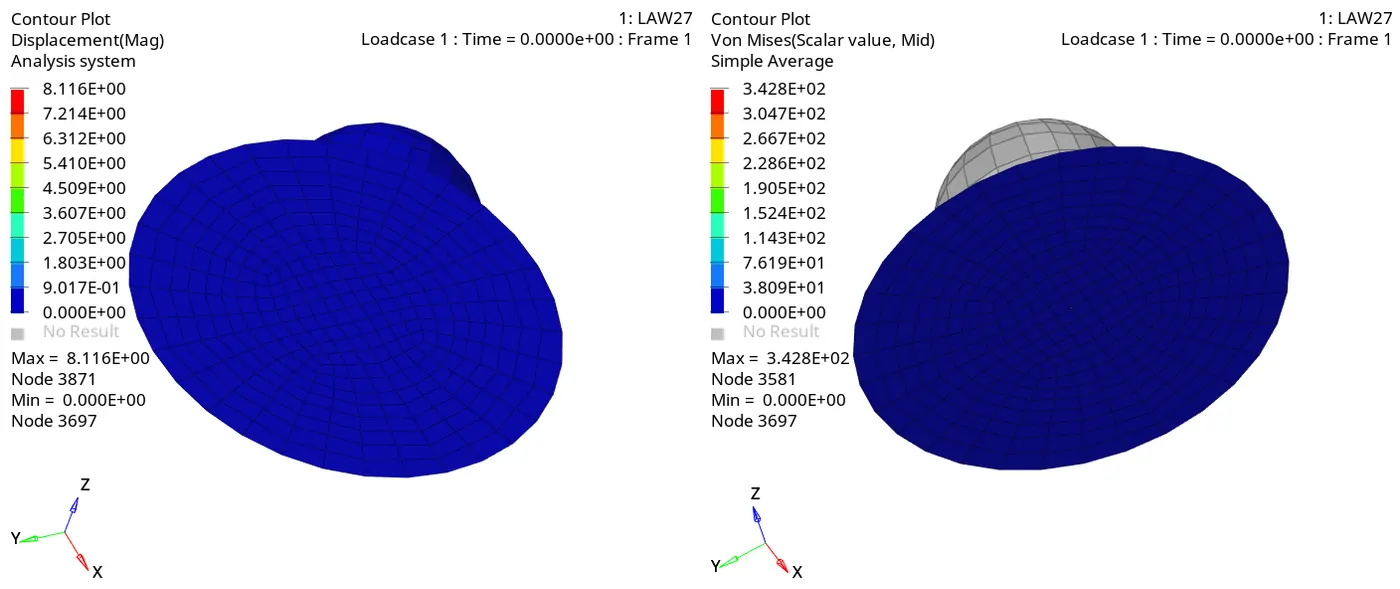
Here we have max.displacement=8.116E+00 and vonmises stress is 342.8MPA and since it is not having a elastic property but having plasticity so we see the deformental changes with elemental removal ,moving ahead to the rad file of 0001 of law 27 certain details shown below along with rad out file image:
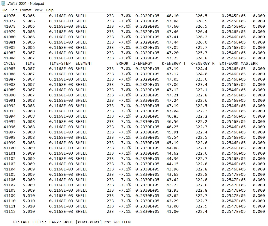
ELAPSED TIME:91.48sec
TOTAL NO.OF CYCLES=41113
MASS ERROR=0%
ENERGY ERROR=-7.1%
This energy error can be considered beacause energy error can be vary from -15% to +5% considered for consideration hence this error is recommandable.Here we have the brittle material that is why after the bearing stress it gets deleted or tear apart completely.
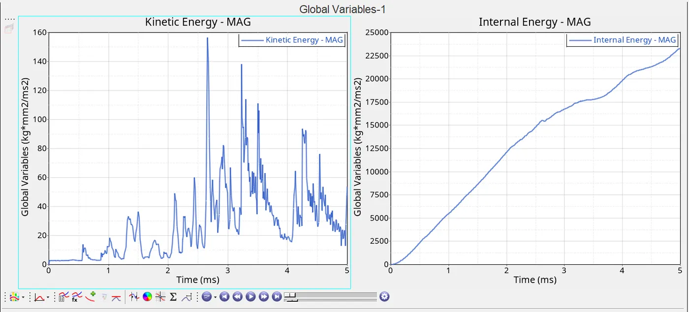
After watching the h3d animation file we gotta go to hypergraph 2D to graphical representation for that we load T01 file first then we have that graph:
Case7:Very first step is to check the material card properties as it is required to run the simulation of law_36 ,for that we choose card image as M36_Plas_tab and other modification are shown below:
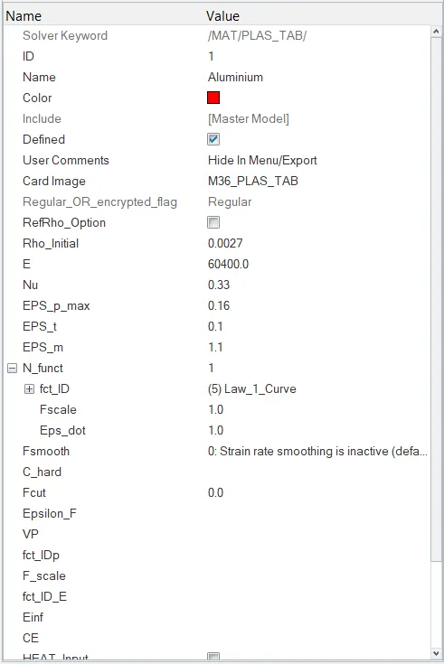
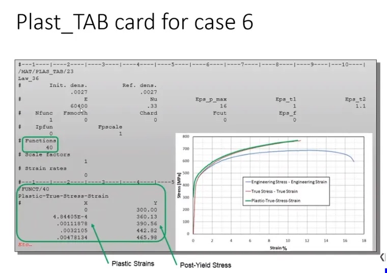
We have taken these values from the material card given in the challenge shown below:
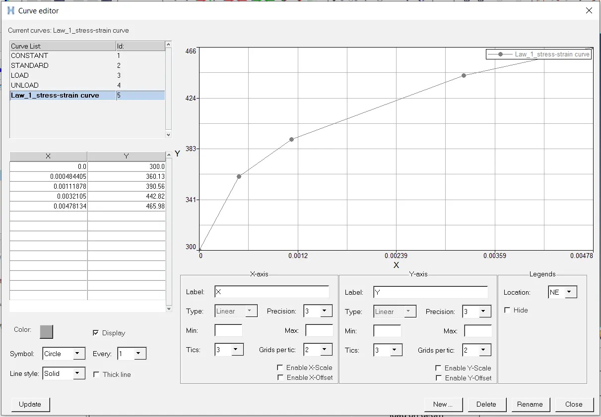
Now we gotta create a curve in which we gotta assign the x and y in order to have the curve formulation shown below:
Now after going for the simulation we should proceed to h3d file of law_36 and we shifting the mode towards the contour mode to take a look of displacement and vonmises stress as shown below:
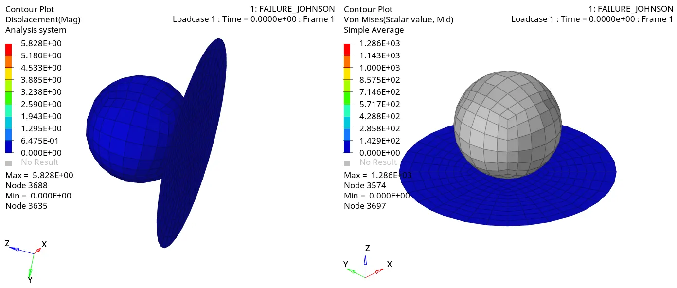
The max.displacement is 5.828E+00mm and the vonmises stress is 128.6MPA
Now proceeding with rad out file of 0001 to take a look to errors and cycles as shown below:
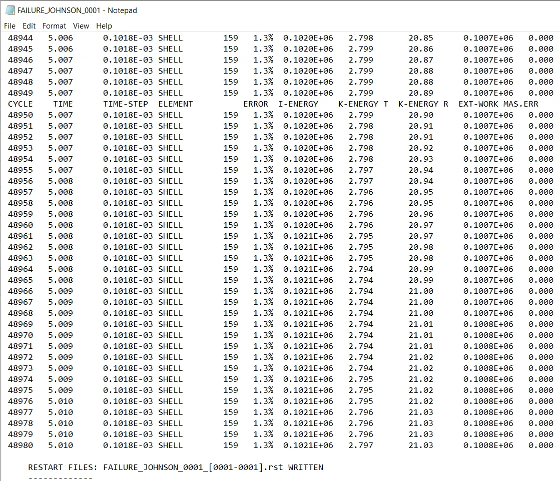
ELAPSED TIME:170.12sec
TOTAL NO. OF CYCLES=48981
TOTAL ENERGY ERROR=1.3%
MASS ERROR=0%
Now shifting the mode towards hypergraph 2D to get a graphical interface and loading the T01 file of it.
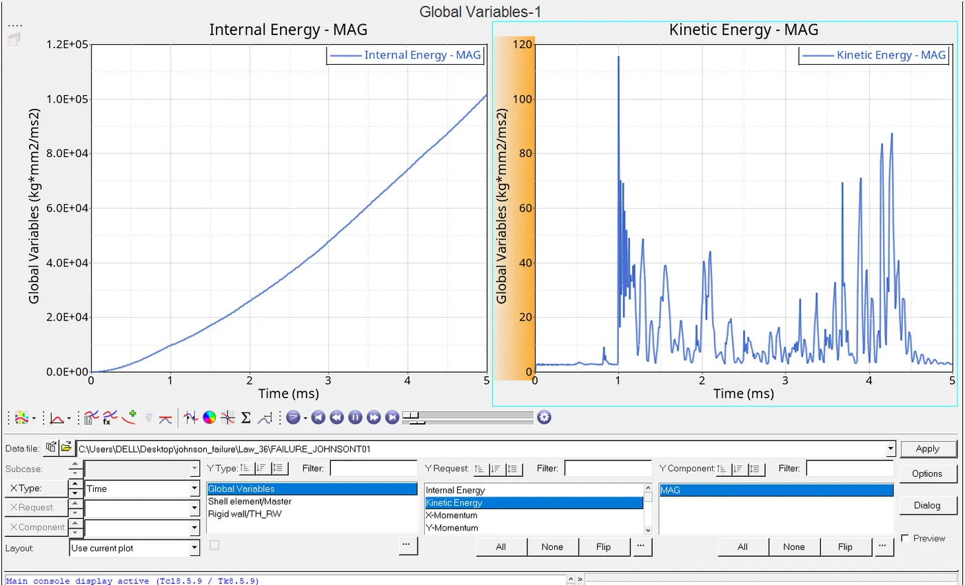
Now as per all the scenarios discussed above are fit to pass the energy criterion which says that energy error could be permissible in between -15% to 5%.
CONCLUSION:(A)Gotta know about many different law method which is being used in rupture plates and got a knowledge of there performances.
(B)From this we have got a method to use of hypergraph 2D,hyperview and hypermesh mode and there several reqiurements.