To study and compare the different material laws in RADIOSS
Objective:
The objective of this exercise is to study different material types in RADIOSS and compare them.
Software used: Hypermesh with RADIOSS
Simulation setup:
Here, we are considering a crash simulation setup for a rupture plate, as shown in the image below.
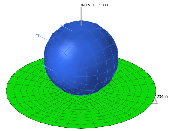
The circular rupture plate is fixed and a spherical ball with some initial velocity is made to strike the rupture plate. Recommended element properties are used for the element formulations, as follows, for faster simulation and good accuracy.
| Parameters | Comment |
|
Ishell =24 |
QEPH 4 nodes shells are best combination of cost and accuracy. |
|
Ismstr=2 |
Full geometric nonlinearities (default)with possible small strain formulation activation in RADIOSS Engine. |
|
Ish3n=2 |
Standard 3 noded shell (C0)with modification for large rotation(default) |
| N=5 | Number of integration points set to 5 for accuracy bending. |
|
Ithick=1 |
Thickness change is taken into account for accuracy. |
|
Iplas=1 |
Iterative plasticity for good accuracy. |
The image below shows the property card created based on recommended properties for explicit analysis.

The material that is being modeled for the rupture plate is Aluminium.
Procedure:
Case 1: LAW2 (PLAS_JOHNS) with /FAIL/JOHNSON
In the first case, the LAW2 (PLAS_JOHNS) material model is used along with the /FAIL/JOHNSON failure model.
LAW2 represents an isotropic elasto-plastic material using the Johnson-Cook material model. In this law, the material behaves as linear elastic when the equivalent stress is lower than the yield stress. For the higher value of stress, the material behavior is plastic. This law is valid for brick, shell, truss, and beam elements. This model expresses material stress as a function of strain, strain rate, and temperature. A built-in failure criterion based on the maximum plastic strain is also available.
This model can be used in combination with the /FAIL/JOHNSON model to get more control over the failure behavior.
The Johnson-Cook failure model is often used to describe the ductile failure of metals. It uses a Johnson-Cook equation to define failure strain as a function of stress triaxiality.
In the Johnson-Cook failure model, there are three parts to the failure model;
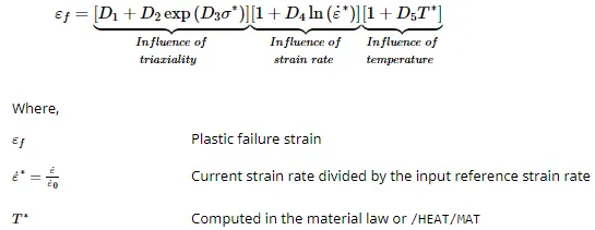
In a simple case where only the triaxiality influence is considered, the failure strain is calculated as,

Element Failure treatment
A cumulative damage method is used to sum the amount of plastic strain that has occurred in the element using:
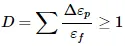
When the D becomes greater than 1, the element is considered failed. What happens when `D≥1` depends on the values of element failure flags (Ifail_sh and Ifail_so ) and XFEM formulation flag (Ixfem).
Here, we are keeping Ixfem equal to zero, therefore, it is expected that the failing elements will be deleted.
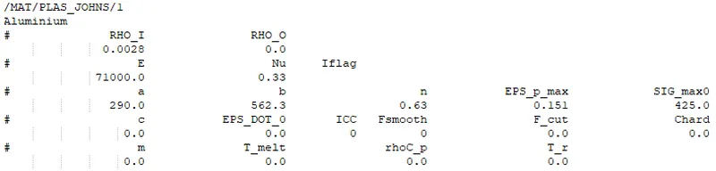
Eps_p_max value is also configured to 0.151, which means the element will be considered fail once the plastic strain for that element reaches this value.
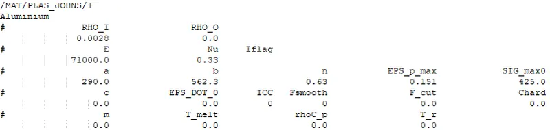
Material card and failure card configurations used are shown in the images below,

Results:
- Total number of cycles: 49379
- Energy error: 0.8%
- Mass error: 0.0
- Simulation time: 67s
Energy error is less than 5% and thus results are acceptable.
The animation below shows the simulation with von mises stress contour,
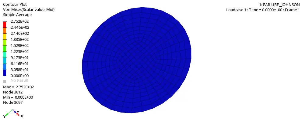
- The maximum stress recorded is 275.2 MPa
- As expected, we can see that the failing elements are deleted during the simulation. The failure of elements is based on Eps_p_max and the criteria defined in the failure card.
The image below shows the energy plot for the simulation,
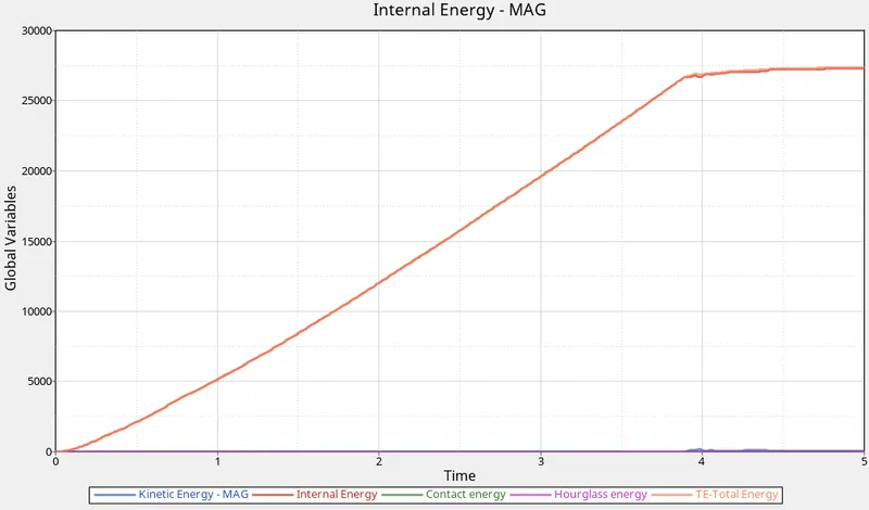
- As the rupture plate was fixed, it had zero total energy initially. After the impact, the internal energy and total energy increases linearly as the plate is resisting the impact and becomes constant after about 3.9ms, when the elements start failing and therefore, can't absorb more energy.
- Also, the internal energy takes few dips once the element starts failing, this is because the energy associated with the deleted elements is dissipated from the system.
- Once the elements start getting deleted, there are spikes noticed in the kinetic energy, as the deleted elements are no longer connected to the fixed plate and have kinetic energy due to impact.
- The maximum energy absorbed as internal energy is 27.3kJ
Case 2: Law2_Epsmax_crack
In the second case, the same previous model files from case 1 are used and the following changes are made to the /FAIL/JOHNSON card.
- Ifail_sh = 1, this would enable the shell element to be deleted or cracked on failure
- Dadv = 1, Criterion for the crack advancement
- Ixfem = 1, the failure criteria will lead to element cracking instead of element or layer deletion
Therefore, the failure criteria are the same in this case but the failure behavior is changed.
Material card and failure card configurations used are shown in the images below,

Results:
- Total number of cycles: 49216
- Energy error: 4.1%
- Mass error: 0.0
- Simulation time: 99s
The energy error is high but is less than 5%, so still acceptable.
The animation below shows the simulation with von mises stress contour,
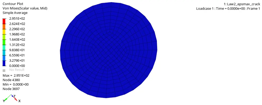
- As expected, we can see the crack formation in the elements before deletion. The failure of elements is based on Eps_p_max and the criteria defined in the failure card.
- The maximum stress recorded is 295.1 MPa which is higher than in the previous case.
The image below shows the energy plot for the simulation,
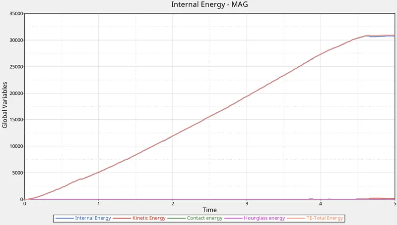
- After the impact, the internal energy and total energy increases linearly as the plate is resisting the impact and becomes constant after about 4.6ms, when the elements start failing and therefore, can't absorb more energy. The peak comes later in this case than in the first case, as the elements are deleted later after crack propagation. And during crack propagation, energy is still being absorbed.
- Also, the internal energy takes few dips once the element starts failing, this is because the energy associated with the deleted elements is dissipated from the system.
- Similarly, the spike in kinetic energy is observed after 4.6ms when the elements started getting deleted.
- The maximum energy absorbed is 30.82 kJ which is higher than in the first case.
Case 3: Law2_Epsmax_nofail
For the third case, the failure card /FAIL/JOHNSON is deleted. All other configuration for the material card is kept same as in the previous case.
Therefore, Eps_p_max is the sole failure criteria present. When plastic strain reaches the value of Eps_p_max in one integration point, then based on the element type:
- Shell elements: The corresponding shell element is deleted.
- Solid elements: The deviatoric stress of the corresponding integral point is permanently set to 0; however, the solid element is not deleted.
Material card configuration used is shown in the image below,
Results:
- Total number of cycles: 49407
- Energy error: 0.8%
- Mass error: 0.0
- Simulation time: 60s
The energy error is less than 5%, so the results are acceptable.
The animation below shows the simulation with von mises stress contour,
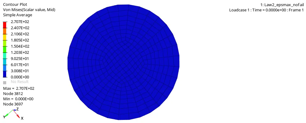
- The maximum stress recorded is 270.7 MPa
- The element failure is based on Eps_p_max, i.e., when the plastic strain goes higher than the Eps_p_max (.151), the element gets deleted.
The image below shows the energy plot for the simulation,
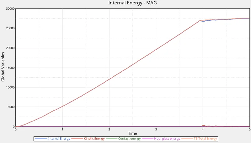
- The maximum energy absorbed is 27.44 kJ which is almost the same as in the first case.
- The overall behavior is also similar to what was observed in the first case.
- The internal energy and total energy increases linearly and at about 3.9ms, elements start failing and deleted. And, both internal and total energy becomes constant.
- There are dips observed in internal energy, after 3.9ms, as the energy associated with the deleted element is dissipated from the system. Also, there are spikes noticed in the kinetic energy, as the deleted elements are no longer connected to the fixed plate and have kinetic energy due to impact.
Case 4: Law2
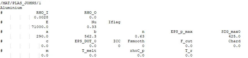
Again, the same model file from the previous case is used. And the value of Eps_p_max is deleted.
The material card configuration used is shown in the image below,
Results:
- Total number of cycles: 48736
- Energy error: 3.0%
- Mass error: 0.0
- Simulation time: 57s
The energy error is less than 5%, so the results are acceptable.
The animation below shows the simulation with von mises stress contour,
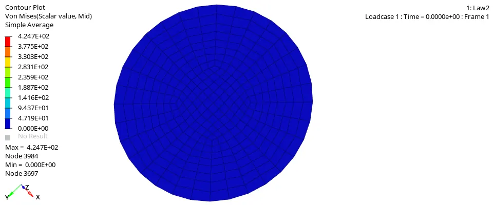
- The maximum stress observed is 424.7 MPa
- No element failure is observed as there are no criteria configured for failure.
- As the material reaches the plastic range it continues to have more strain but since the SIG_max value is defined as 425 MPa, the stress doesn't go beyond it.
The image below shows the energy plot for the simulation,
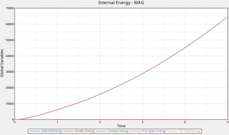
- The total energy and internal energy keeps on increasing until the end of the simulation as there is no material failure and the strain keeps on increasing. The kinetic energy is also observed to be negligible.
Case 5: LAW1 (/MAT/ELAST)
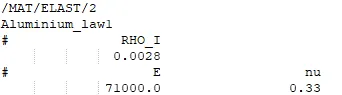
In this case, the LAW1 material card is used to model the material for the rupture plate.
This law defines an isotropic, linear elastic material using Hooke's law. This law represents a linear relationship between stress and strain. It is available for truss, beam (type 3 only), shell, and solid elements. This material law is used to model purely elastic materials.
The material configuration used is shown in the image below,
Results:
- Total number of cycles: 47968
- Energy error: 1.3%
- Mass error: 0.0
- Simulation time: 65s
The energy error is less than 5%, so the results are acceptable.
The animation below shows the simulation with von mises stress contour,
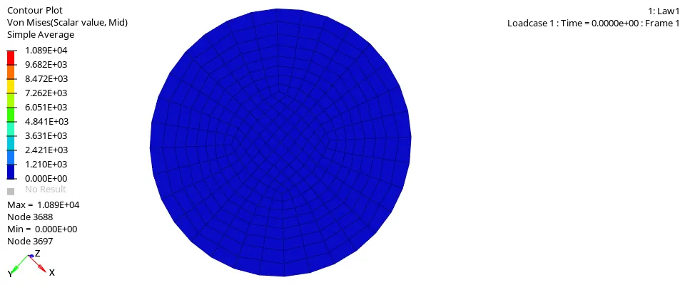
- As this material law models elastic behavior, there is no material failure and after the load is removed, the material rebounds to its original shape.
- The Von mises stress is way higher at 10890 MPa, which is totally impractical.
The image below shows the energy plot for the simulation,
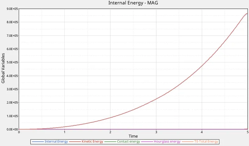
- The internal energy and correspondingly total energy keep on increasing exponentially during the simulation as there is no material failure and the plate keeps on deforming.
Case 6: LAW36 (/MAT/PLAS_TAB)
In this case, LAW36 is used to model the material for the rupture plate.
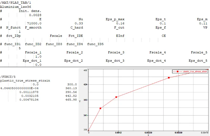
This law models an isotropic elasto-plastic material using user-defined functions for the work-hardening portion of the stress-strain curve for different strain rates. This law is available for brick and shell elements. The elastic portion of the material's stress-strain curve is defined by Young modulus and Poisson's ratio. Material plasticity curves can be given for an arbitrary number of strain rates.
There are two damage and rupture parameters:
- Once plastic strain reaches Eps_p_max (maximum plastic strain), in one integration point, the element is deleted.
- If the largest principal strain reaches Eps_t, the stress is reduced using the following relation,
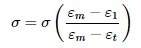
If the largest principal strain reaches Eps_m, the stress in the element is reduced to 0 (but the element is not deleted).
Once the largest principal strain reaches Eps_f (maximum tensile failure strain), the element is deleted.
The material configuration used is shown in the image below,
Results:
- Total number of cycles: 52198
- Energy error: -1.4%
- Mass error: 0.0
- Simulation time: 73s
The energy error is less than 5%, so the results are acceptable.
The animation below shows the simulation with von mises stress contour,
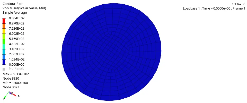
- The maximum stress recorded is 930.4 MPa
- The element failure is based on Eps_p_max, i.e., when the plastic strain goes higher than the Eps_p_max (.151), the element gets deleted. However, there is no element deletion based on maximum tensile failure strain as the value for it was not defined, and in such case, a very high value 3.0 x 1030 is used as default.
The image below shows the energy plot for the simulation,
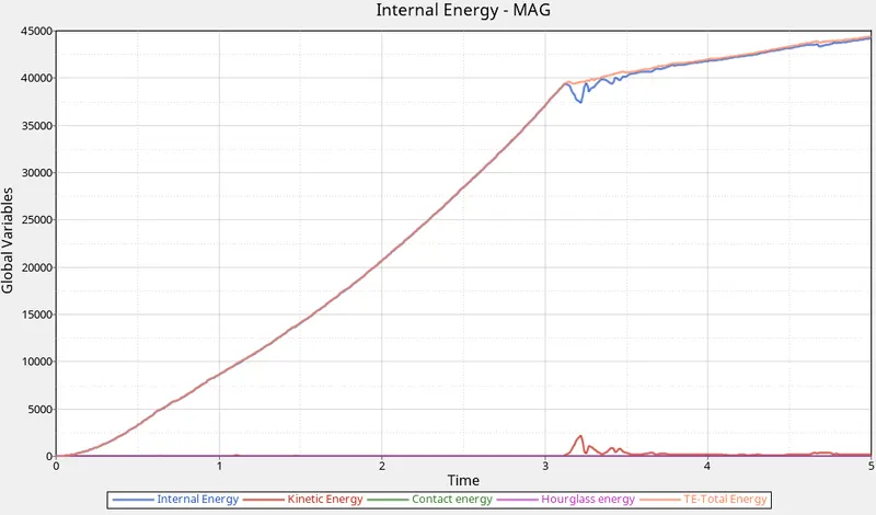
- The internal energy and total energy increases linearly and at about 3.1ms elements start failing and deleted and after that internal energy and total energy increases very slowly.
- As the elements start getting deleted, there are few dips observed in the internal energy as the energy associated with the deleted elements is dissipated from the system. For the same reason, there are spikes observed in the kinetic energy after 3.1ms.
- The total energy peaks at about 44.29 kJ.
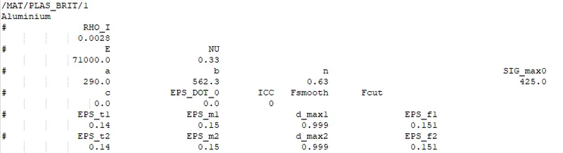
Case 7: LAW27 (/MAT/PLAS_BRIT)
In this case, LAW27 is used to model the material for the rupture plate.
This law combines an isotropic elasto-plastic Johnson-Cook material model with an orthotropic brittle failure model. Material damage is accounted for prior to failure. Failure and damage occur only in tension. This law is applicable only for shells.
This law allows the modeling of material damage and brittle failure in two principal directions.
Material damage and rupture are defined with four parameters for each principal direction:
- Eps_t: strain at the beginning of tensile failure.
- Eps_m: Maximum tensile strain at which stress in the element is set to a value dependent on d_max.
- d_max: Maximum damage factor.
- Eps_f: Maximum tensile strain for element deletion.
The material configuration used is shown in the image below,
Results:
- Total number of cycles: 49507
- Energy error: 0.8%
- Mass error: 0.0
- Simulation time: 69s
The energy error is less than 5%, so the results are acceptable.
The animation below shows the simulation with von mises stress contour,
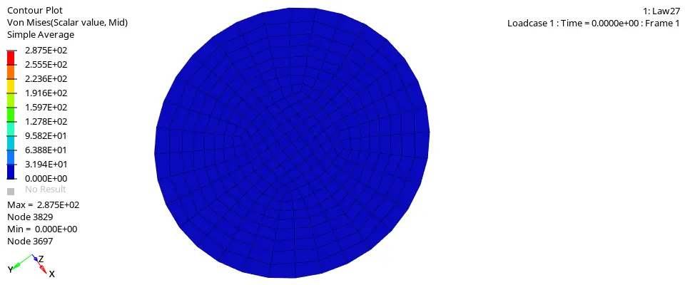
- The maximum stress recorded is 287.5 MPa
- We can observe the material is failing as a brittle material and element failure is based on brittle failure parameters defined.
The image below shows the energy plot for the simulation,
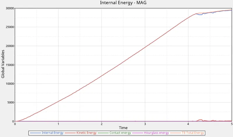
- The internal energy and total energy increases linearly and at about 4.1ms elements start failing and deleted and after that internal energy and total energy increases very slowly.
- As the elements start getting deleted, there are few dips observed in the internal energy as the energy associated with the deleted elements is dissipated from the system. For the same reason, there are spikes observed in the kinetic energy after 3.1ms.
- The total energy peaks at about 29.54 kJ.
Conclusion:
All seven cases were successfully simulated and analyzed. All the cases gave acceptable results based on the energy error and mass error. Hourglass energy was also zero in all the cases.
Case 2, Case 6, and Case 7 provided the best results for the material failure. Overall, Case 6 would give the best results if accurate lab data is available for the material. Case 4 and 5 are not at all suitable for simulations involving large deformations like in crash analysis.