Analysis on Rupture Plate for different Cases
Aim and Objective
To Simulate the Rupture Plate and run for different cases and infer the results
Case Setup and Execution
Case 1
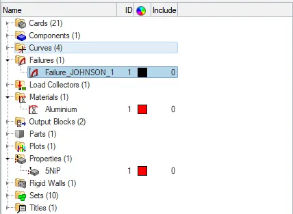
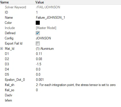
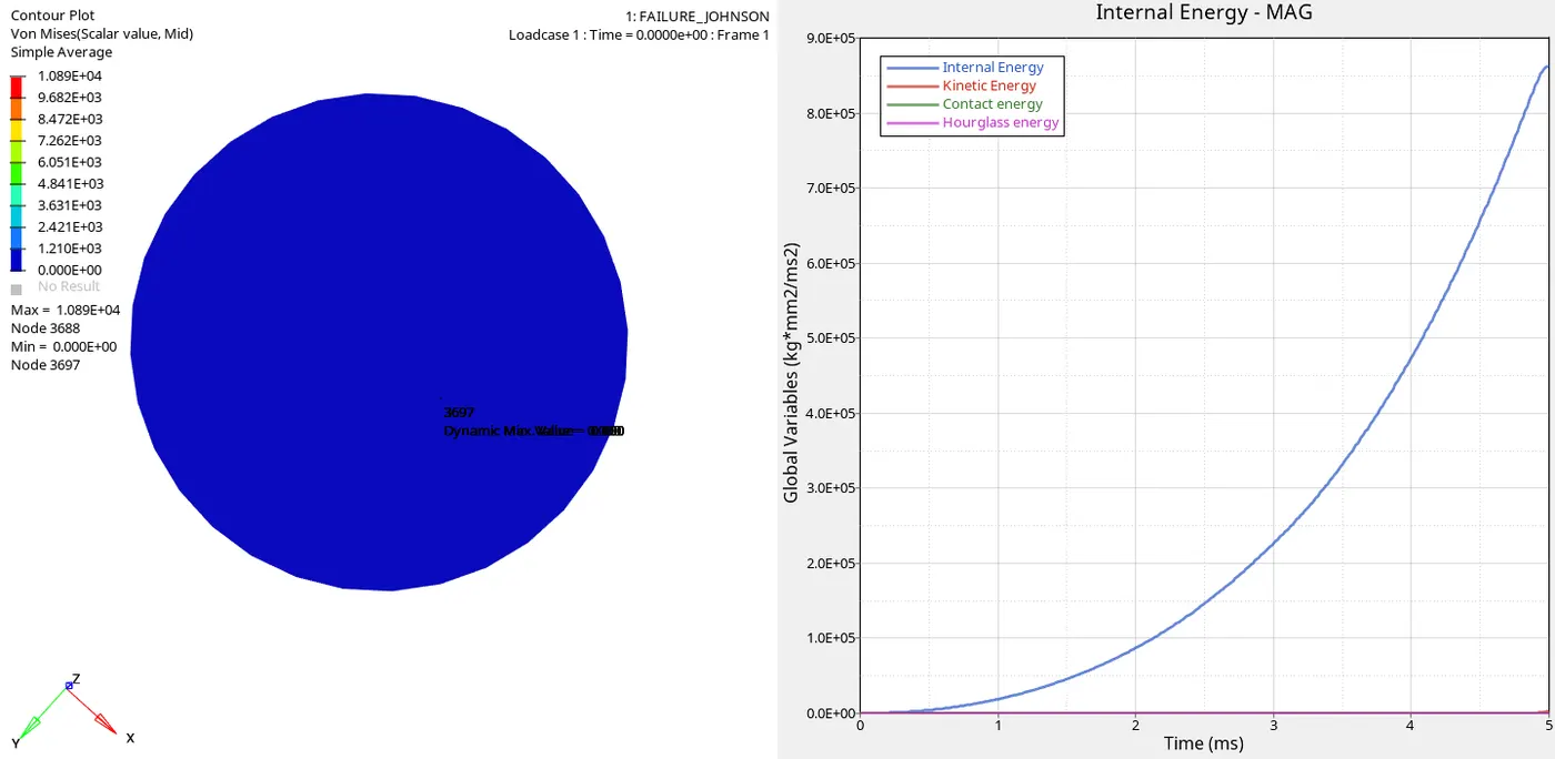
Default given file FAILURE_JOHNSON_0000 and FAILURE_JOHNSON_0001 was given and analysis was done
Material Properties
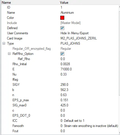
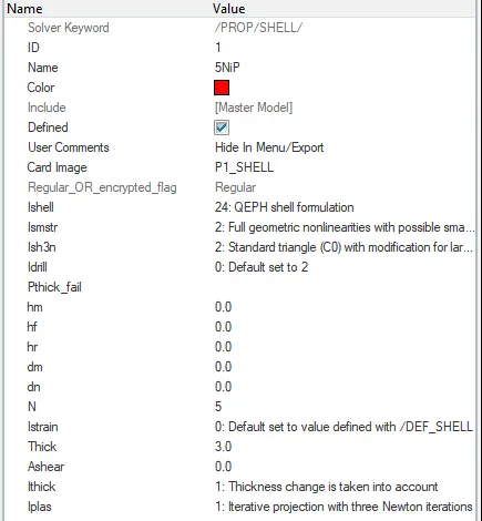
Image and Graph
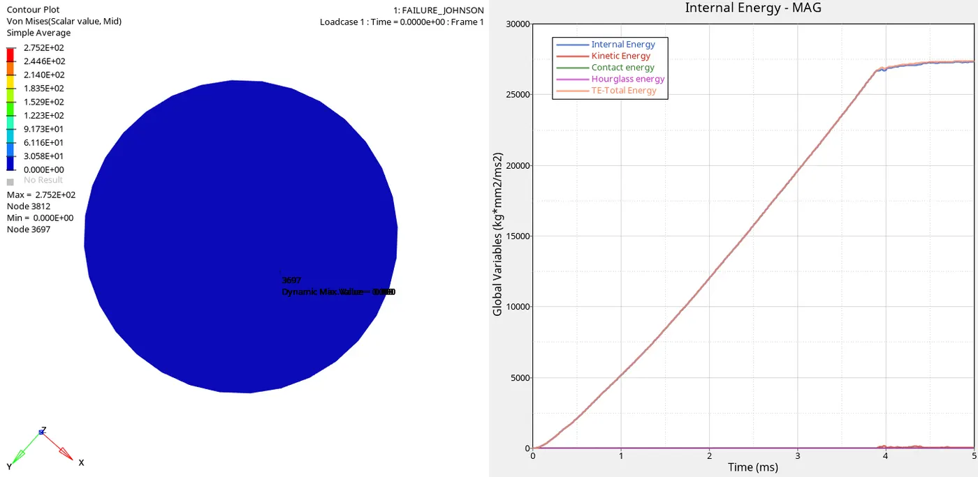
Inference
- Johnson failure card is used Law 2 is applied
- `sigma = a+b epsilon^n_p;` considering Temperature and strain rate as constant
- Isotropic elasto- plastic behaviour is applied
- Von mises hardening takes place without damage
- `epsilon_f =[ D1+D2 exp(D3 sigma^@)]` Maximum Stress, EPS_p_max are defined so, failure elements are predefined
- If Ixfem =0: failure - elements are deleted
Case 2
Same model in Failures Changed ifail_sh =1; Dadv=1 ; Ixfem =1 and analysis was done
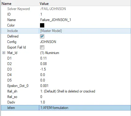
Image and Graph
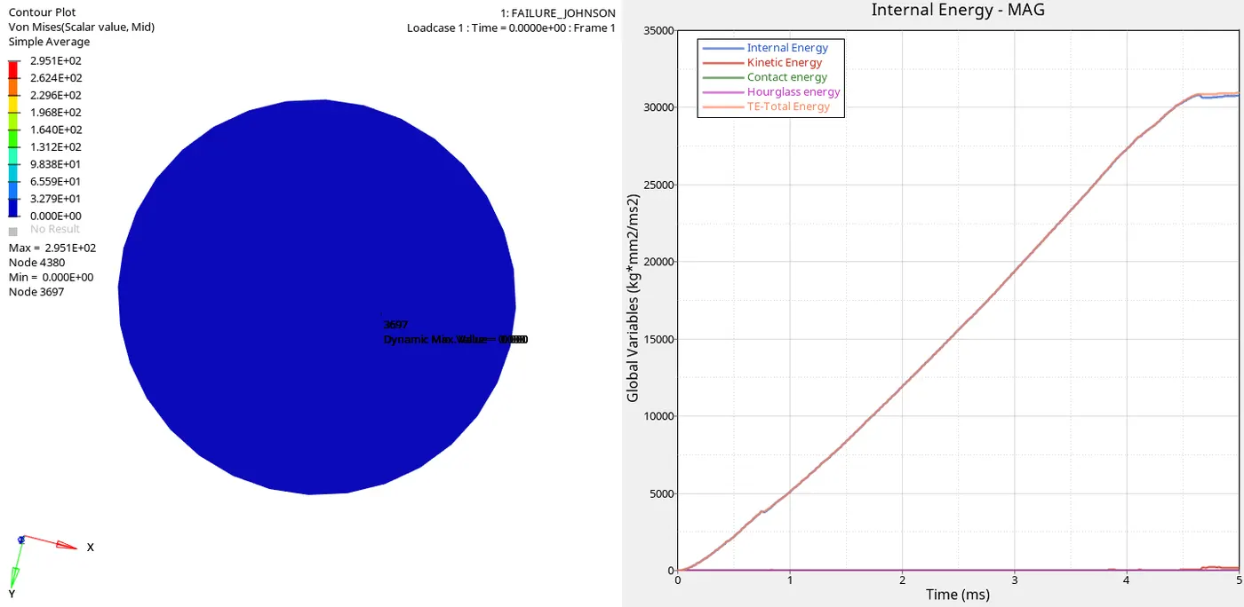
Inference
- In this case Same model is run by changing
- Ifail_sh = 1 ; If Ixfem =1: failure - element cracked.
- Dadv =1 Then Dadv = 1 (max accumulation damage value D, used for crack initiation)
- Ixfem =1 ;Realistic behaviour can be observed- Discipates Energy; Represents crack over an element
Case 3
Same model Deleted Failure and Analysis was done
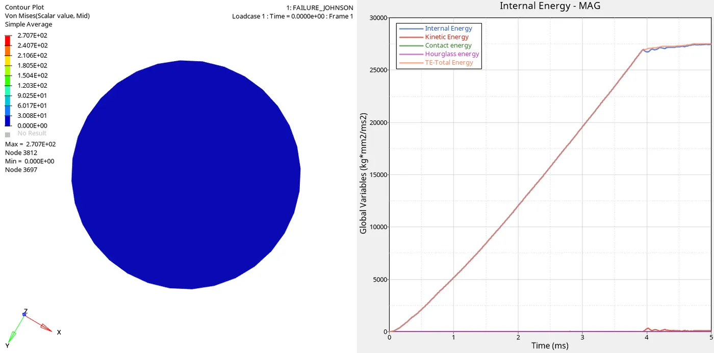
Image and Graph
Inference
- In this case same model is run for analysis but failure card is deleted
- Now element deformation takes place based on EPS_p_max and Maximum stress value
- As the failure card is deleted we can see elements are getting deleted.
Case 4
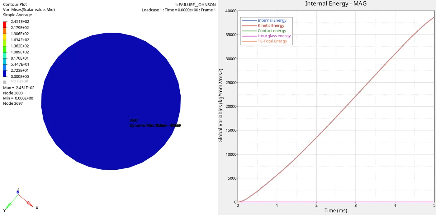
Deault file was taken, In materials Properties Eps_p_max value was made 0 and analysis was done
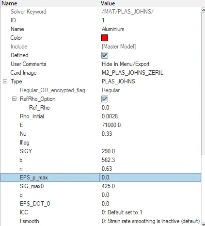
Image and Graph
Inference
- EPS_p_max it is material failure determining criteria; it also defines when/ at which particular integration point the elemet fails
- When EPS_p_max is equal to 0 we can see the elment is getting deleted un-uniformly unrealistic manner
Case 5
Default file was taken Material Property was changed to Law 1 M1_ElAST default values were given analysis was done
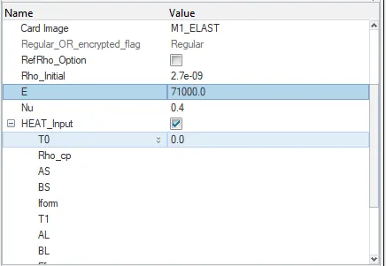
Image and Graph
Inference
M1_ELast
- It applies for linear elastic material based on hooke's law
- This material card is used to models of purely plastic materials
- As we can see in animation the impact is unrealistic
- It's like impact taking on a blanket rather than rupture plate
- The impact on model is non linear so, Law27 can be substituted instead of Law1
- The deformation is smooth and cracking at the end pointwise.
Case 6
Given LAW27_0000.rad file is imported and analysed with default conditions
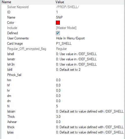
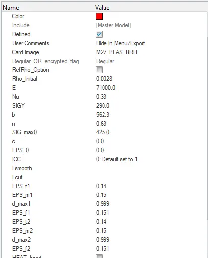
Image and Graph
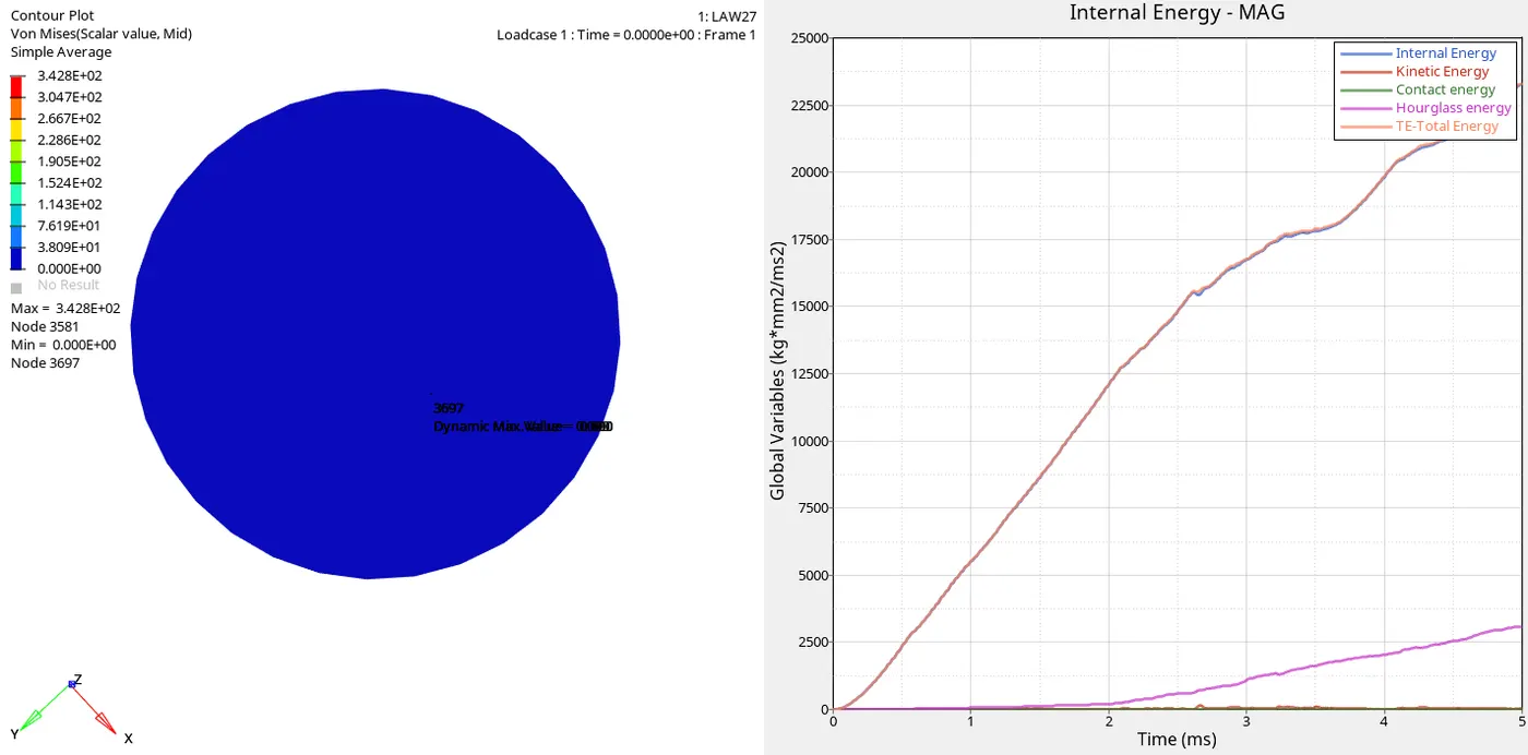
Inference
- Law 27 is Elastic Plastic Brittle
- As we can clearly see the element is getting deleted
- I_shell, I_smstr , I_sh3n, I_thick are default values due to which there is increase in hourglass energy
- Uneven distribution of elements during impact
- Nodal distribition issue is found
- Irregular pattern of impact is seen
Case 7
Given file FAILURE_JOHNSON_0000.rad is imported and new Curve is added with Stress VS Strain graph and analysed by applying Law 36 M36_PLAS_TAB
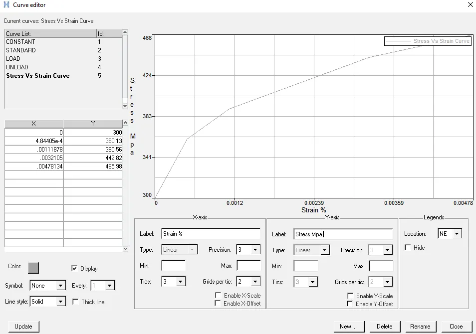
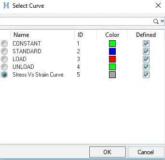
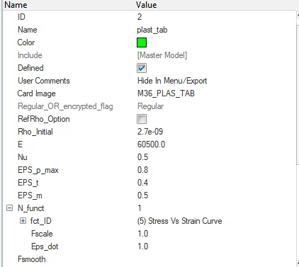
Image and Graph
Inference
- In this case Stress Strain curve is defined from experimented values
- Law36 is applied; Elastic Plastic - Tabulated
- Failure johnson card is defined
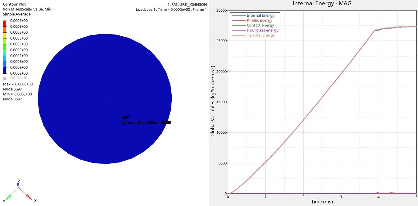
- The Elements are deleted during impact
- Ixfem is 0 in this case so, failure creteria based on `epsilon` which is dependent on D1 D2 D3 values
- Higher curve leads to higher strain which is faster failure
Graphs
- If we look into graphs Engergies are similar with slight variations except in case 6 and 5(Parabolic) there has been increase in hourglass energy due shell properties
- Case 5 has parabolic curve which shows elastic property
- Case 7 better results can be obtained by changing Stress Strain values
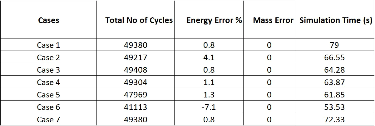
This data is taken from _0001.out file of every case when opened using Notepad
Results and Conclusion
- If we look into case 6 energy error is -7.1% it means more energy has been discipated
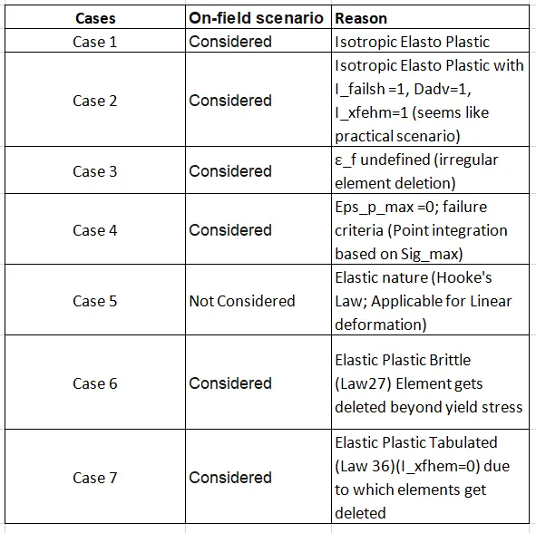
- In case 2 due to effect of I_failsh , Dadv, Ixfehm values had effect on element deformation
- Remaining cases except case5 the Simulation can be accepted for on field scenario; Case 5 Law 1 is applied based on linear deformation
- But here in rupture plate the deformation is non linear
- In case 1 the analysis is based on `epsilon_f`value and sig_max value as EPS_p_max value is 0
- In case 3 deletion of elements due to deletion of Failure card; deletion of elements is based on Ixfehm
- In case 4 Ixfehm = 0 with failure card; but elments were deleted based on `epsilon_f` value
- In case 5 is based on law 1 which is applicable for linear deformation; the simulation unrealsitic and impractical
- In case 6 LAW 27 is applied , In which beyond yield stresss the material damage is accounted before failure
- In case 7 LAW 36 is applied; higher the curve higher strain then faster failure; better results can obtained by altering Stress Strain values.