Assignment 3
AIM:
1) To run the simulations on the given "Crash Beam" file with "Run Time" as "55 milli seconds" and "Number Of Animation Steps" as "50".
2) This Simulation should be first done by "Without modifying any Element properties" and the second simulation by "Changing all the element properties which are provided".
OBJECTIVE:
1) After Running the simulations with and without Element properties, we have to check for "ENERGY ERRORS" AND "MASS ERRORS".
2) If the Errors are in Acceptable Range then we should Plot all the energies below with "TIME":
- Rigid wall Forces
- Internal Energy
- Hourglass Energy
- Contact Energy
- Total Energy
PROCEDURE:
CASE : 1
First we have to "IMPORT THE CRASH BEAM FILE": "Element_Formulation-shell-3_assignment_0000.rad" to "HYPERWORKS 2020" through "SOLVER DECK" as shown below:
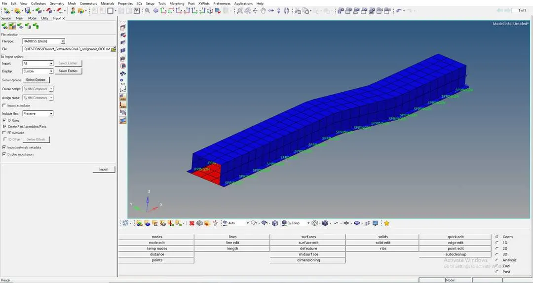
After importing this file to "HYPERWORKS 2020", We have to GOTO 'Analysis' > 'Radioss'.
Q.1. Changing Run Time to "55 milli seconds": Run time should be changed in Cards, In that we have to goto "ENG_RUN" and then changing in "Tstop" as shown below:
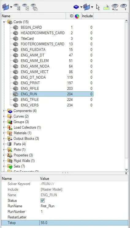
Q.2. Changing Number of Animation steps as "50" during simulation, and this "Frequency" Calculation is done by:
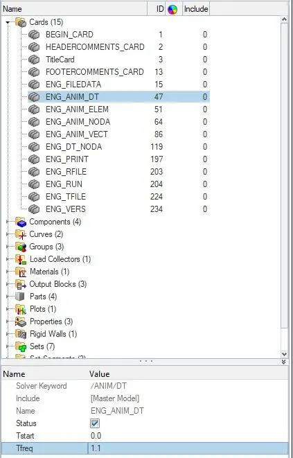
"Run time / Number Of Animation Steps" = 55/50 = 1.1.
This value is changed in "ENGINE_ANIM_DT" as shown below:
Q.3. Now the simulation is runned without changing any "Element Properties" OR with "Default Element properties" as shown below:
Q4. "ENERGY ERRORS" AND "MASS ERRORS" ARE AS SHOWN BELOW: Here we should open the RADIOSS output file: "Element_Formulation-shell-3_assignment_0001.out".
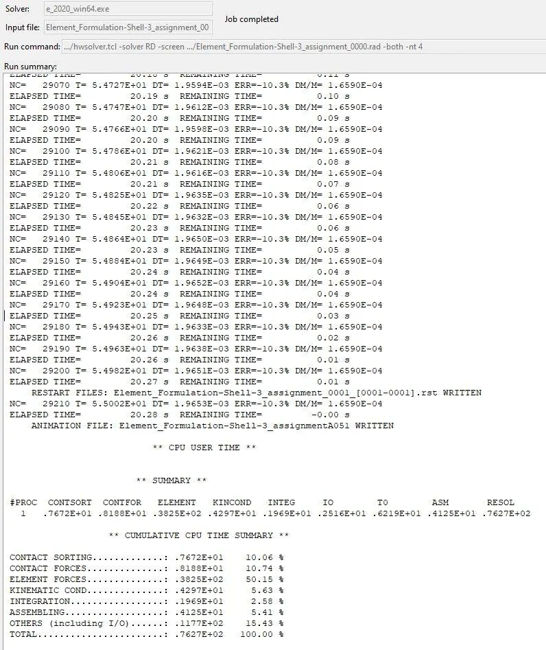
Here in CASE-1 the "ENERGY ERROR" at the end of the simulation is "-10.3%", this is acceptable because in any simulation the acceptable "ENERGY ERROR" should be between "-15% to +5%".
Q.5
PLOTS OF "RIGID WALL FORCES" VS "TIME":
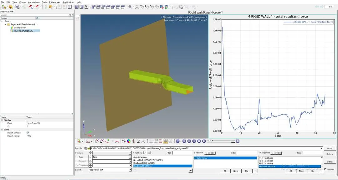
Here initially at "Time:0", the Force experienced by the Rigid Wall by crashing the given component is "Very High" , but as the time passes the Force Experienced during the crash is getting "Lower and lower".
But at "20th second" and after "50th second" as per the above graph, the force experienced by the "Rigid wall" is quite "HIGH", this is because the contact between the "COMPONENT" and "RIGID WALL" will be more at this particular time.
PLOTS OF ["INTERNAL ENERGY", "HOURGLASS ENERGY", "CONTACT ENERGY" , "TOTAL ENERGY"] ALL VS "TIME" as shown below:
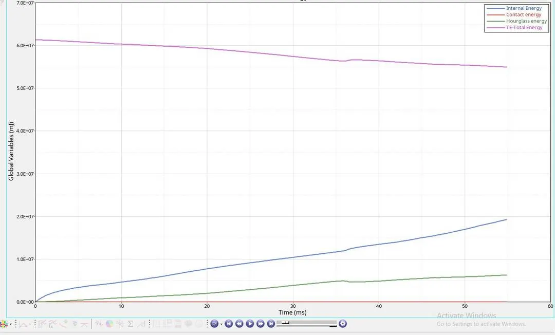
From the above plots we can see that:
- "Internal Energy" or the "Strain energy" increases with time as the deformation of the given component keeps on increasing due to the Crash which is happening in the simulation.
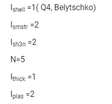
- "Hourglass Energy " is increasing as time passes, so by this we can know that "Hourglass effect" or "Hourglass deformation" is taking place, this is because we are using "Reduced Integrated Element" or "Underintegrated Elements" i.e.. "Q4 (Belytschko) Elements" which is having only "One Itegration point" in an element, This is a physical energy where it shows no sign of stress created.
- "Contact Energy", here the component is in contact with the rigid wall the whole time, so the contact energy is nill the whole simulation.
- "Total Energy" , here the Total energy depends on "Hourglass Energy", "Total Energy" and "Internal Energy", we can see that "Total Energy" is decreasing as time passes, this is because "Hourglass Energy" is increasing.
CASE : 2
Q.6.
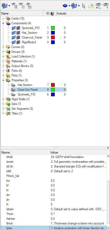
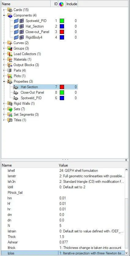
Here we do the simulation by changing all the "SHELL ELEMENT PROPERTIES" to the "RECOMMENDED PROPERTIES" as shown below:
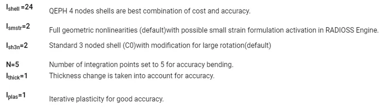
We should change all these above properties in both "HAT SECTION" AND "CLOSE OUT PANEL" Property parameters as shown below:
CLOSE OUT PANEL:
HAT SECTION:
After changing all the parameters we have to run the simulation by goingto: 'Analysis' > 'Radioss'
After running the simulation with the above given properties we get "ENERGY ERRORS" AND "MASS ERRORS" as shown below:
Here we should open the RADIOSS output file: "Element_Formulation-shell-3_assignment_0001.out".
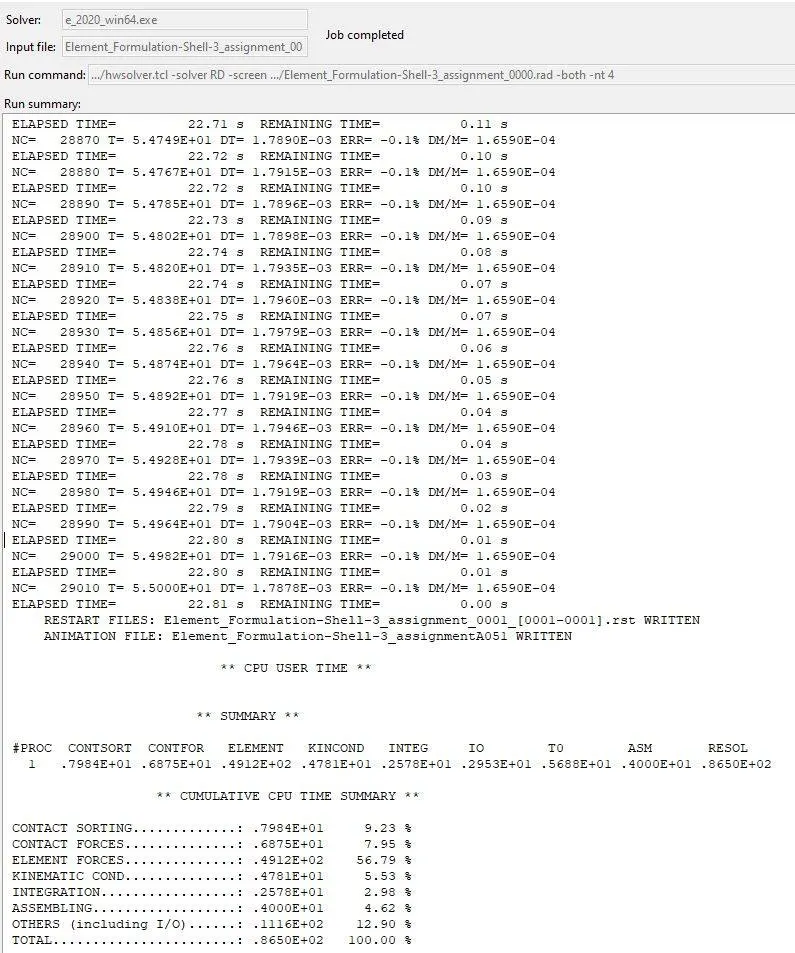
Here in CASE-2, "ENERGY ERROR" at the end of the simulation is "-0.1%", This value is very much acceptable and closer to "0%"
PLOTS OF "RIGID WALL FORCES" VS "TIME":
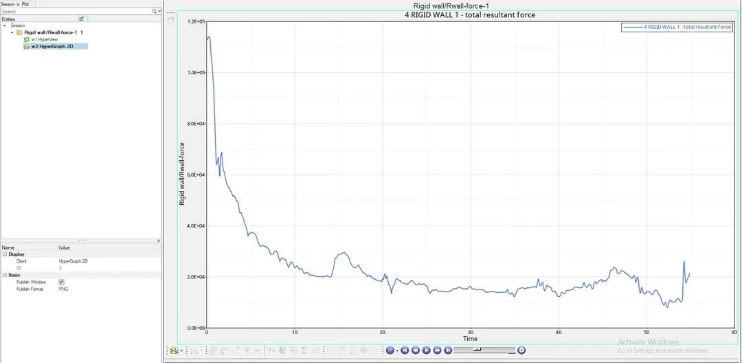
Here initially at "Time:0", the Force experienced by the Rigid Wall by crashing the given component is "Very High" , but as the time passes the Force Experienced during the crash is getting "Lesser and lesser".
But here we don't see a sudden raise in Force at "20th and 50th" second, as we saw in previous simulation.
PLOTS OF ["INTERNAL ENERGY", "HOURGLASS ENERGY", "CONTACT ENERGY" , "TOTAL ENERGY"] ALL VS "TIME" as shown below:
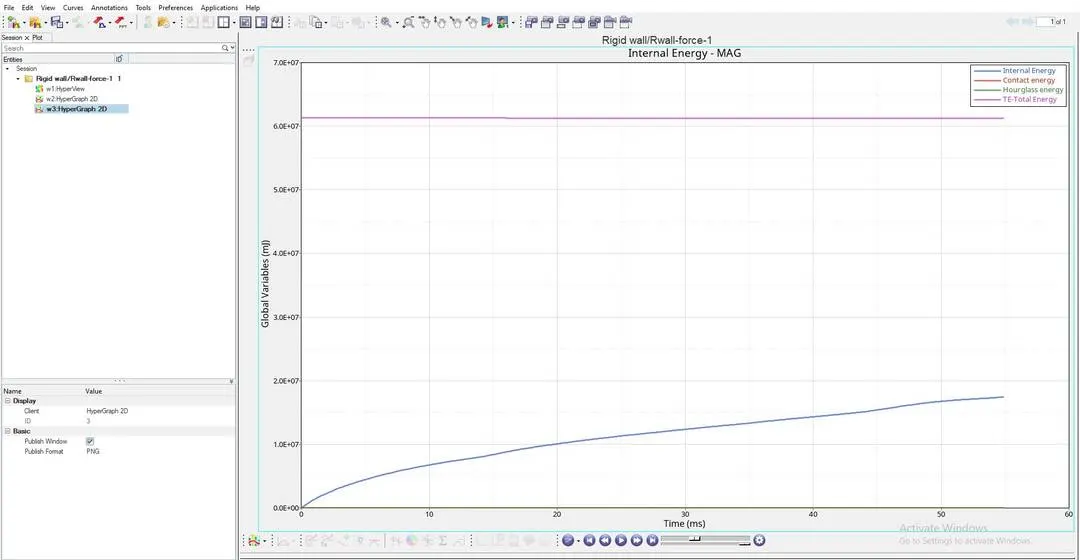
From the above plots we can see that:
- "Internal Energy" or the "Strain energy" increases with time as the deformation of the given component keeps on increasing due to the Crash which is happening in the simulation.
- "Contact Energy", here the component is in contact with the rigid wall the whole time, so the contact energy is nill the whole simulation.
- "Hourglass Energy", here from the above graph we can see that there is no "Hourglass Effect" or "Hourglass Deformation" experienced by the given component, this is because we are using "QEPH SHELLS" which are "Improved Integrated Elements", so we can say that this element "Opposes the Hourglass Effect" or "Stabilizes the Hourglass Effect" in a component.
- "Total Energy", here the Total energy depends on both "Hourglass Energy", "Contact Energy" and "Internal Energy", we can see that "Total Energy" is nill at 6x10^7mj, this is beacause there is no "Hourglass Effect" or "Hourglass deformation" on the component.
Q.8 and Q.9
COMPARING THE RESULTS FROM BOTH THE SIMULATIONS:
a] "Internal Energy": Even called as "Strain energy" increases with time as the deformation of the given component keeps on increasing due to the Crash in Both the simulations.
b] "Contact Energy": Contact Energy is "Nill" in both the simulations.
c] "Hourglass Energy" and "Total Energy"
We can see the "Hourglass Effect" or "Hourglass Deformation" due to the use of "Underintegrated Elements", so this proves that use of "Underintegrated Elements" like "Q4-SHELL" cannot stop this "Hourglass deformation" which also affect "Total Enenrgy" in "CASE-1".
Due to the use of "QEPH SHELL" which is an "Improved Integrated Elements" , there is is no "Hourglass Deformation", because this "QEPH ELEMENTS", uses "PERTUTBATION METHOD" to reduce "Hourglass Deformation", This method induces "STIFFNESS" on the material level where ever the component is experiencing the "HOURGLASS DEFORMATION", since the "STIFFNESS" is induced at material level, the material will be stiffned before any hourglass deformation occurs.
After using this "Improved Integrated Elements" we can see that the "Total Energy" is not affected.
d] "Energy Error"
In "CASE-1", "ENERGY ERROR" is "-10.3%", this is because of the effect of "Hourglass Deformation" on "Total Energy", so here the "ENERGY ERROR" is quite "HIGH" but acceptable.
In "CASE-2", "ENERGY ERROR" is "-0.1%", very close to "0", since we have used "QEPH-SHELLS" there is no "Hourglass effect" on the material, this is why we can see that "Total Energy" is not affected in this 2ND case.
CONCLUSION:
Simulation is carried out "Without changing any element properties" and "BY changing all the shell element properties to Recommended properties", all the results are noted down and understood the difference between both the simulations.