Comparison of base simulation and Improved Shell Element Properties for Crash beam using Radioss in Hypermesh
AIM :
Comparison of results with base simulation(Case-1) and improved shell element properties(Case-2) by using crash beam file as per given run time,animation steps,Shell element properties to recomended properties conditions and running the simulation. Finally check the energy error and mass error and plot the results.
OBJECTIVE :
Comparison of results with base simulation and improved shell element properties
1.Using the crash beam file , change the run time to 55 ms.
2. Change the number of animation steps during simulation to a minimum of 25 and maximum of 60.
3. Run the base simulation without any modification to element properties.
4. At the end of the simulation, do the energy error and mass error checks and determine whether results would be acceptable.
5. If acceptable, Plot rigid wall forces, internal energy, hourglass energy, contact energy, total energy of the simulations.
6. Change all the shell elements properties to recommended properties, save this as separate, rad files and run the simulation.
Recommended properties:
| Parameters | Comment |
|
Ishell =24 |
QEPH 4 nodes shells are best combination of cost and accuracy. |
|
Ismstr=2 |
Full geometric nonlinearities (default)with possible small strain formulation activation in RADIOSS Engine. |
|
Ish3n=2 |
Standard 3 noded shell (C0)with modification for large rotation(default) |
| N=5 | Number of integration points set to 5 for accuracy bending. |
|
Ithick=1 |
Thickness change is taken into account for accuracy. |
|
Iplas=1 |
Iterative plasticity for good accuracy. |
7. Follow steps 5 and 6.
8. Create a brief report comparing all the results from steps 5 and 6 for both simulations.
9. Comment whether there is any change in the results and why there is any change in the result.
SOFTWARE USED : Radioss in Hypermesh
THEORY :
Energy Error must be negative and decreasing (except for the first cycles or in spring back stage). The error must be less than 15% at the end of the computation(5% for a good model). If the error increases a little and then decreases may be normal. If the error increases, this means that problem has occured. Then the error may grow to 99.9% with computation failure message. So ideally the error should be at most -15% and better to have -5%. Mass error must be very low, error value from (0-1) is better.
Kinetic Energy of an object is the energy that it possess due to its motion. It is defined as the work needed to accelerate a body of a given mass from rest to its stated velocity. Having gained this energy during its acceleration, the body maintains this kinetic energy unless its speed changes.
The internal energy of a thermodynamic system is the energy contained within it. It is the energy necessary to create or prepare the system in any given internal state. It does not include the kinetic energy of motion of the system as a whole, nor the potential energy of the system as a whole due to external force fields, including the energy of displacement of the surroundings of the system. It keeps account of the gains and losses of energy of the system that are due to changes in its internal state. The internal energy is measured as a difference from a reference zero defined by a standard state.
Hourglass Deformation - When the stress and strain computed on the nodes, all the elements will be calculated through integration points. when a force F is applied to node, first the acceleration of node will be calculated by the solver, then the velocity, and finally the displacement. From the displacement, the solver will calculate the strain considering the material properties, and from the strain, the stress will be computed which will be applied as a force on the node next node. This goes on until the force is completely used up by the model. When the elements in a model deform but the strain energy is not computed for that deformation then it results in the Hourglass deformation.
- These integration points are the points that are placed on the element to calculate the results from the nodes. Here the results in the elements are integrated using Gaussian Quadrature from the node through the integration points.There are two types of integrated elements, reduced and fully integrated elements.
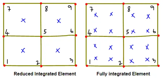
- In the case of a fully integrated element, the results from the nodes 1,2,4 and 5 will be calculated at the integration points respectively. Since there are four integration points the result computed at the element is going to be very accurate but on the other hand, the solver has to solve the result for four points because of this the computational cost is going to be very high.
- In the reduced integration element, the solver will calculate the nodal result only at one point, and thus it is computationally inexpensive. In this case, there are two disadvantages first being the inaccuracy and second, being the Hourglass Deformation. The reason for the hourglass deformation to take place only in the reduced element is because of the less integration point.
Fix for the Hourglass deformation:
There are a few fixes for this hourglass deformation,
- Stiffness can be added to the reduced integration element at the material level where this hourglass is occurring. In most of the solvers, this is done automatically provided you have activated the card.
- A damping force can be added at the deformation, depending upon the deformation the force will be computed. This can be done for the problem with high velocity eg, blast simulations. This can also be done by activating the respective card form the solver.
- By using the fully integrated elements this Hourglass deformation can be avoided.
- Mesh refinement will also help in avoiding this Hourglass deformation. Coarse mesh along with less integration point is more prone to Hourglass deformation.
PROCEDURE :
CASE - 1 : WITH BASE SIMULATION
Running the Simulation :
1. Importing the crash beam file in Hypermesh by using Import Model option and select the file to import and click import.
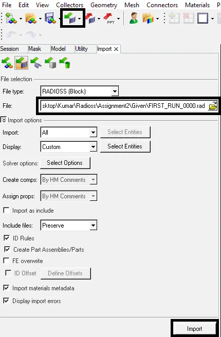
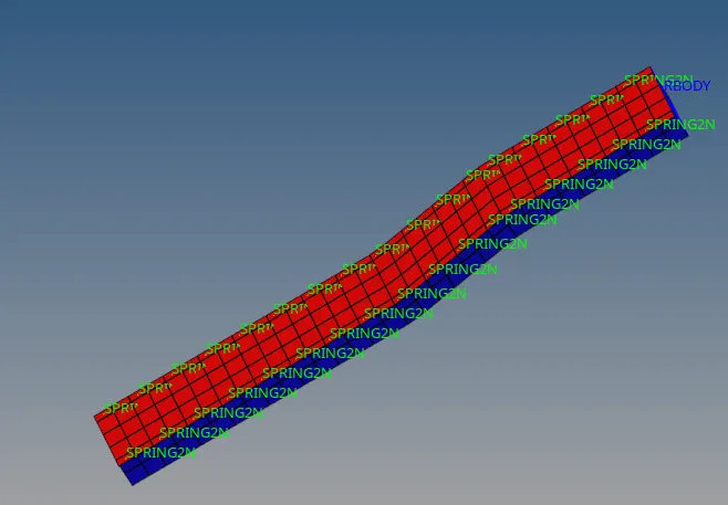
Fig : Importing Crash Beam File
2. After Importing the crash beam file, Change the run time to 55ms.
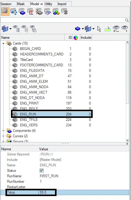
Fig : Simulation Run Time
3. For Changing the number of animation steps during simulation to a minimum of 25 and maximum of 60, Set the frequency time(Tfreq) by dividing total run time and no.of.animation steps.
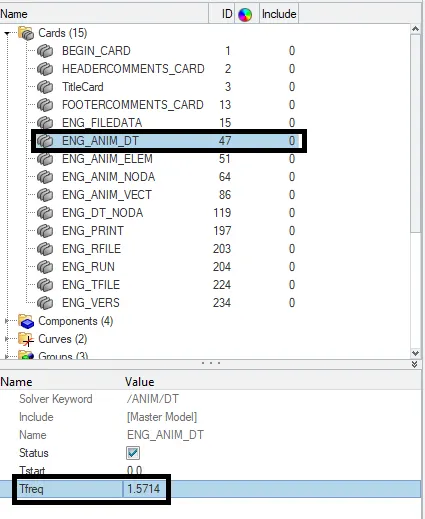
Fig : Frequency time
4. After setting run time & Frequency time, Go to Analysis-->Radioss option and save the input file in new folder and set options and run the simulation.

Fig : Running the simulation
Error Checking :
5. After running the simulation, Open the Engine Out file from the saved folder and check the energy error and mass error.

Fig : Energy error and Mass error
6. Energy error(better to have -5%), it showing as -10.3%, because Hourglass Energy is artificially created. Mass error is 0.1659E-03 %.
Von Mises Stress Contour Plot :
7. Change Hypermesh into HyperView and load the FIRST_RUN.h3d model file and Click Apply.
8. Select the Contour icon and set Result type as Vonmises stress and click Apply.
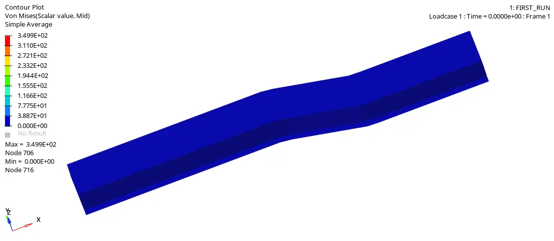
Fig : Vonmises stress Contour Plot
9. From the above plot we know that, That the material fails when the maximum normal stress value induced in the material is more than the yield point value, so normal stress theory doesn't work in most of the cases. The most preffered failure theory used in industry is Von mises stress based. We note that Von mises stress is at maximum towards the fixed end of the beam and this is less than the yield point value, so design is safe. If the Maximum value of Von mises stress induced in the material more than the strength of the material, then design will fail. So to Keep Maximum value of Von mises stress induced in the material is less than its strength of the material, so that design will be safe.
Rigid Wall Forces Plot :
10. Change HyperView into HyperGraph 2D to plot the Rigid wall forces as a function of time.
11. Load the time history file FIRST_RUNT01 file. and Select Rigid wall forces and then click Apply.
12. Select the Y-type,Y-Request and Y-Component as Rigid wall-->4 RIGID WALL 1-->total resultant force and click Apply.
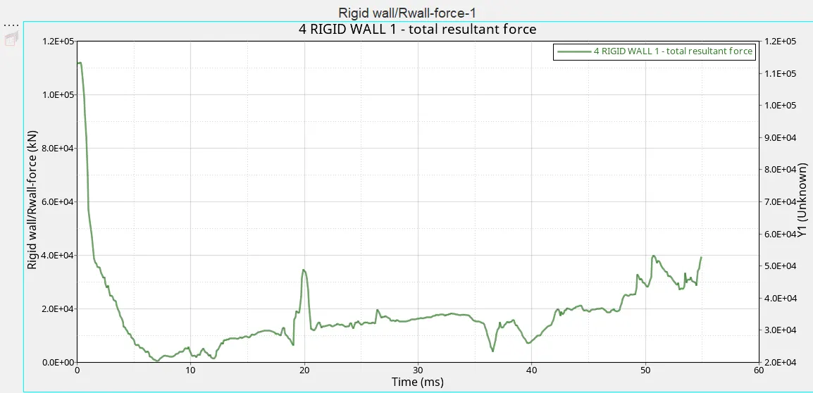
Fig : Rigid Wall Forces Plot
13. Total resultant force will be high initially at sudden impact is (1.1E+05 kN) and then force will be decreased. Rigid wall Force will vary according to the stress acting on the element.
Energy Plot :
14. Select the Y-type,Y-Request and Y-Component as Global Variables-->Internal Energy, Kinetic Energy,Contact Energy,Hourglass Energy,Total Energy-->Mag and click Apply.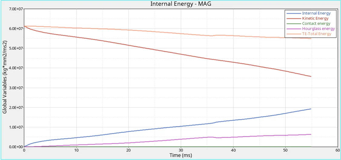
Fig : Energy Plot
15. From the above Energy Plot we observed that,
- When the Beam is crashed on the rigid wall, Kinetic Energy will start to loss energy of the system (from 6.0E+07 to 3.5E+07`(kg*mm^2)/(ms^2)`).
- While Kinetic Energy losses, Internal Energy start to gain energy of the system (from 0.0E+00 to 2.0E+07 `(kg*mm^2)/(ms^2)`) due to changes in its internal state.
- We Know that Total Energy is sum of all energy. Whenever Kinetic energy losses & Internal Energy gains, Total energy should be stable. But in this case Total Energy Plot shows decreasing(below 6.0E+07 `(kg*mm^2)/(ms^2)`) due to reduced integration element method is used.In the reduced integration element, the solver will calculate the nodal result only at one point, and thus it is computationally inexpensive. In this case, there are two disadvantages first being the inaccuracy and second, being the Hourglass Deformation.
- The reason for the hourglass deformation to take place only in the reduced element is because of the less integration point. When the elements in a model deform but the strain energy is not computed for that deformation then it results in the Hourglass deformation. Due to Hourglass Deformation, Hourglass Energy is artificially created(from 0.0E+00 to 0.6E+07 `(kg*mm^2)/(ms^2)`). So that Total Energy is not Stable.
Merge Plot (Vonmises stress Contour, Energy & Rigid Wall Force Plot) :
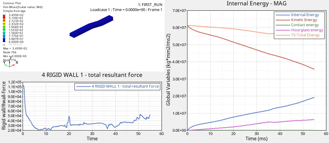
Fig : Animation and Graphs Merged
CASE - 2 : IMPROVED SHELL ELEMENT PROPERTIES
1. Importing the crash beam file in Hypermesh by using Import Model option and select the file to import and click import.
2. After Importing the crash beam file, Change the run time and frequency time as same as case-1.
3. Go to Properties and Change the shell element properties as per given recommended properties.
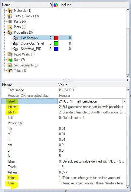
Fig : Element Property Settings
4. After setting run time,Frequency time & Element Properties, Go to Analysis-->Radioss option and save the input file in new folder and set options and run the simulation.
Error Checking :
5. After running the simulation, Open the Engine Out file from the saved folder and check the energy error and mass error.

Fig : Energy error and Mass error
6. For QEPH shell formulation or fully integrated elements, the Energy error can be slightly positive since there is no hourglass energy and the computation is much more accurate. An error of 1 or 2% will be acceptable. In this case Energy error is -0.1 %. Otherwise any positive energy error means energy has been created which indicates a model issue. Mass error is 0.1659E-03%, error value from (0-1) is better.
Von Mises Stress Contour Plot :
7. Change Hypermesh into HyperView and load the FIRST_RUN.h3d model file and Click Apply.
8. Select the Contour icon and set Result type as Vonmises stress and click Apply.
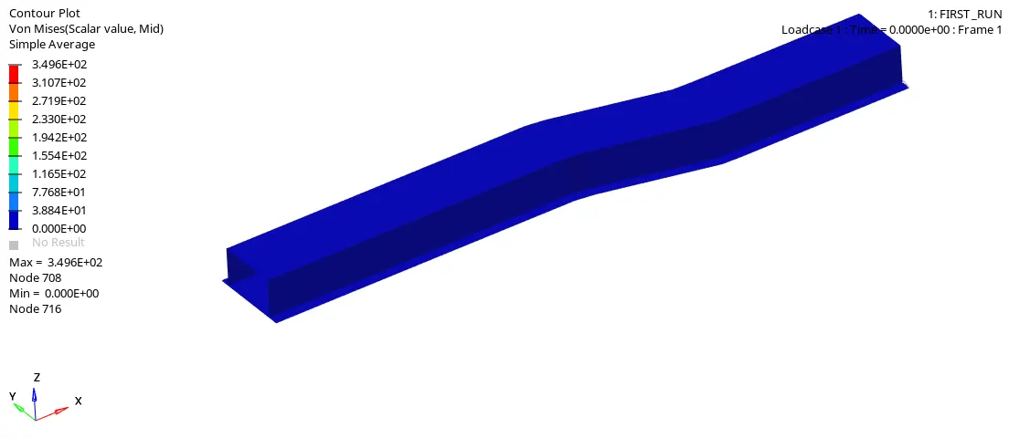
Rigid Wall Forces Plot :
9. Change HyperView into HyperGraph 2D to plot the Rigid wall forces as a function of time.
10. Load the time history file FIRST_RUNT01 file. and Select Rigid wall forces and then click Apply.
11. Select the Y-type,Y-Request and Y-Component as Rigid wall-->4 RIGID WALL 1-->total resultant force and click Apply.
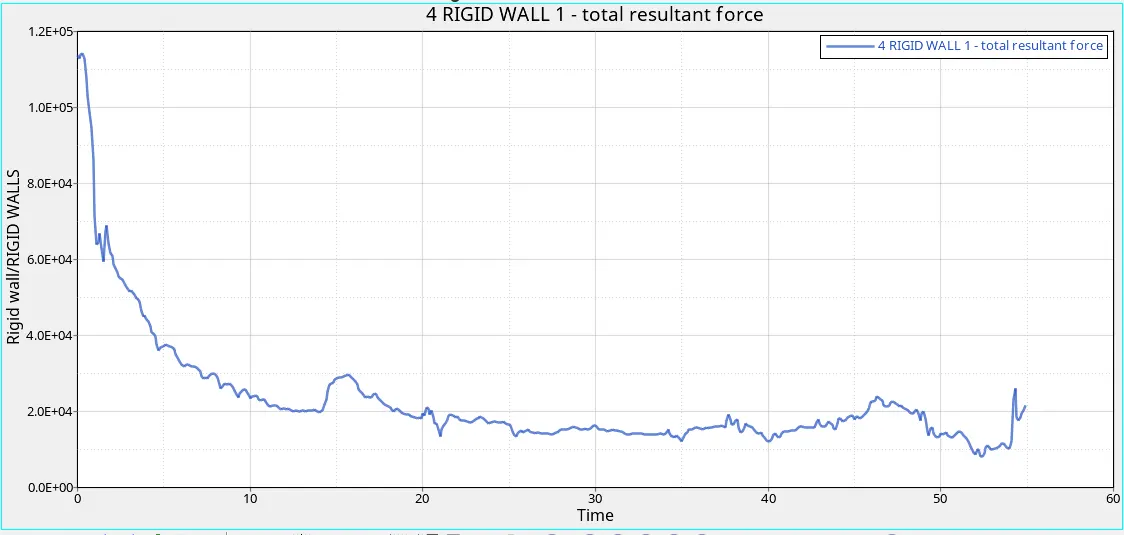
Fig : Rigid Wall Force Plot
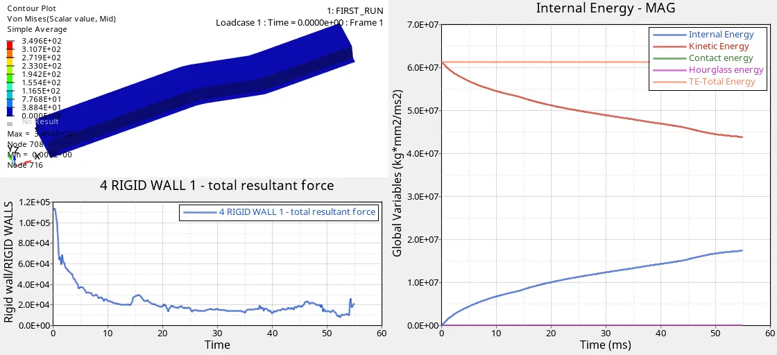
12. Total resultant force will be high initially at sudden impact is (1.1E+05 kN) and then force will be decreased. Rigid wall Force will vary according to the stress acting on the element and there is stress distribution is gradually decreasing based on the rigid wall.
Energy Plot :
13. Select the Y-type,Y-Request and Y-Component as Global Variables-->Internal Energy, Kinetic Energy,Contact Energy,Hourglass Energy,Total Energy-->Mag and click Apply.
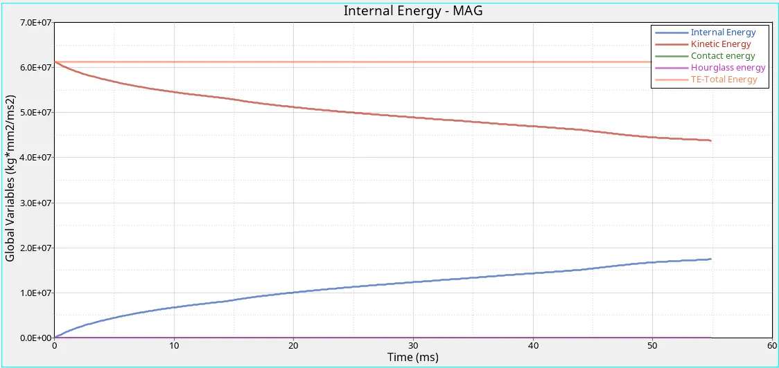
Fig : Energy Plot
14. From the above Energy Plot we observed that,
- When the Beam is crashed on the rigid wall, Kinetic Energy will start to loss energy of the system (from 6.0E+07 to 4.4E+07 `(kg*mm^2)/(ms^2)`).
- While Kinetic Energy losses, Internal Energy start to gain energy of the system(from 0.0E+00 to 1.8E+07 `(kg*mm^2)/(ms^2)`) due to changes in its internal state.
- We Know that Total Energy is sum of all energy. Whenever Kinetic energy losses & Internal Energy gains, Total energy should be stable. In this case Total Energy Plot shows stable (at 6.0E+07 `(kg*mm^2)/(ms^2)`).
- There is no Hourglass Deformation occurs in this case, Because Shell element Properties has been improved by changing Ishell as QEPH. In QEPH Parameter Physical stabilization method is used to fix for the Hourglass Deformation. Physical Stabilization method is adding stiffness to the reduced integration element at the material level where this hourglass is occuring. So there is no Hourglass Energy (0.0E+00 `(kg*mm^2)/(ms^2)`) .

Fig : QEPH Shell Property
Merge Plot (Vonmises stress Contour, Energy & Rigid Wall Force Plot) :
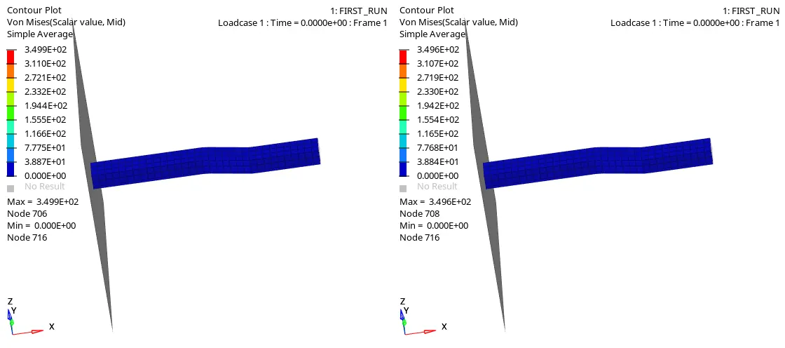
Comparision of Von Mises Stress Contour plot:
Case -1 : With Base Simulation Case - 2 : Improved Shell Element Property
COMPARISION OF RESULTS :
| S.No. | Parameter | CASE - 1 : BASE SIMULATION | CASE - 2 : IMPROVED SHELL PROPERTIES |
| 1 | Energy error |
Energy error(better to have -5%), it showing as -10.3%, because Hourglass Energy is artificially created. |
For QEPH shell formulation or fully integrated elements, the Energy error can be slightly positive since there is no hourglass energy and the computation is much more accurate. An error of 1 or 2% will be acceptable. In this case Energy error is -0.1 %. Otherwise any positive energy error means energy has been created which indicates a model issue. |
| 2 | Mass error |
Mass error is 0.1659E-03. |
Mass error is 0.1659E-03, error value from (0-1) is better. |
| 3 | Rigid Wall Force |
Total resultant force will be high during the time of start is (1.1E+05 kN) and then force will be decreased. When there is a bend in the Material, force will sudden increase and then decreases. |
Total resultant force will be high during the time of start is (1.1E+05 kN) and then force will be decreased. When there is a bend in the Material, force will sudden increase and then decreases. |
| 4 | Kinetic Energy |
When the Beam is crashed on the rigid wall, Kinetic Energy will start to loss energy of the system (from 6.0E+07 to 3.5E+07`(kg*mm^2)/(ms^2)`). |
When the Beam is crashed on the rigid wall, Kinetic Energy will start to loss energy of the system (from 6.0E+07 to 4.4E+07 `(kg*mm^2)/(ms^2)`). |
| 5 | Internal Energy |
While Kinetic Energy losses, Internal Energy start to gain energy of the system (from 6.0E+07 to 2.0E+07 `(kg*mm^2)/(ms^2)`) due to changes in its internal state. |
While Kinetic Energy losses, Internal Energy start to gain energy of the system(from 0.0E+00 to 1.8E+07 `(kg*mm^2)/(ms^2)`) due to changes in its internal state. |
| 6 | Total Energy |
We Know that Total Energy is sum of all energy. Whenever Kinetic energy losses & Internal Energy gains, Total energy should be stable. But in this case Total Energy Plot shows decreasing(below 6.0E+07 `(kg*mm^2)/(ms^2)`) due to reduced integration element method is used.In the reduced integration element, the solver will calculate the nodal result only at one point, and thus it is computationally inexpensive. In this case, there are two disadvantages first being the inaccuracy and second, being the Hourglass Deformation. |
We Know that Total Energy is sum of all energy. Whenever Kinetic energy losses & Internal Energy gains, Total energy should be stable. In this case Total Energy Plot shows stable (at 6.0E+07 `(kg*mm^2)/(ms^2)`). |
| 7 | Hourglass Energy |
The reason for the hourglass deformation to take place only in the reduced element is because of the less integration point. When the elements in a model deform but the strain energy is not computed for that deformation then it results in the Hourglass deformation. Due to Hourglass Deformation, Hourglass Energy is artificially created(from 0.0E+00 to 0.6E+07 `(kg*mm^2)/(ms^2)`). So that Total Energy is not Stable. |
There is no Hourglass Deformation occurs in this case, Because Shell element Properties has been improved by changing Ishell as QEPH. In QEPH Parameter Physical stabilization method is used to fix for the Hourglass Deformation. Physical Stabilization method is adding stiffness to the reduced integration element at the material level where this hourglass is occuring. So there is no Hourglass Energy (0.0E+00 `(kg*mm^2)/(ms^2)`) will be created. |
CONCLUSION :
By running the simulation of Case-1 (with base simulation) & Case-2(improved shell element properties) and compared two case results of Energy error, Mass error, Rigid wall force, Internal Energy,Total Energy, Contact Energy, Hourglass Energy and observed that Case-2 gives better results due to improved shell element properties.