Assignment 3
AIM:To perform the simulation in a 2D shell element with and without modification and comparing there results with each other as per the given data on the given model.
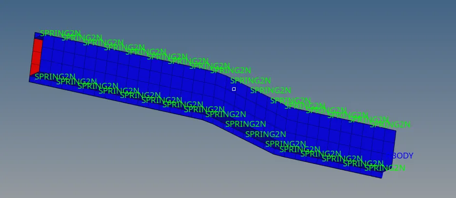
PROCEDURE:Firstly we need to import the model for the given rad file and the model obtained from it as shown below:
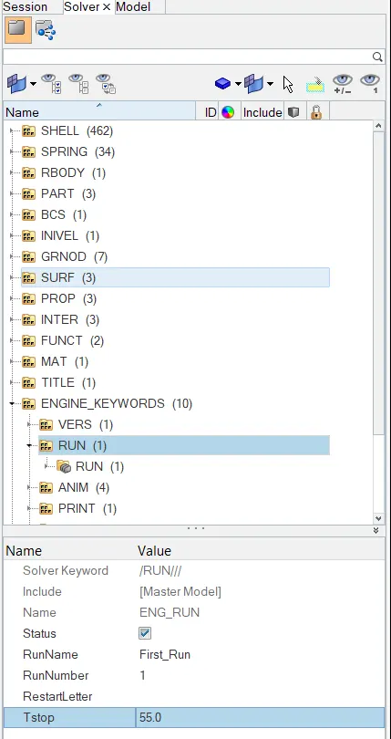
1.Using the crash beam file from the previous assignment, change the run time to 55 ms.
ANS: So the run time can easily be changed in the SOLVER where we find lots of options available in which we gotta go for ENGINE_KEYWORDS under it we have RUN and in it Tstop available where we just changed it shown below:
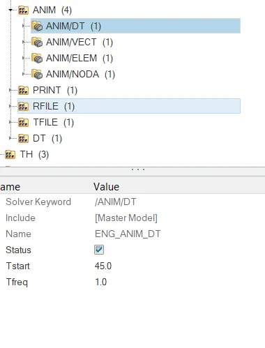
2. Change the number of animation steps during simulation to a minimum of 25 and maximum of 60.
ANS:However the Tstop is taken 55ms ,so we got to pick a random value which do exist in between with minimum time as 25ms and Tstop,let us assume 45ms is the Tstart time and Tfreq is taken as 1.Apparently Tfreq is not numeric no. but a ratio of Tstop/Tstart ,so can be taken as 1.Which has been shown below:
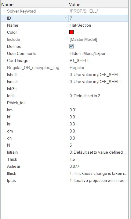
3. Run the base simulation without any modification to element properties.
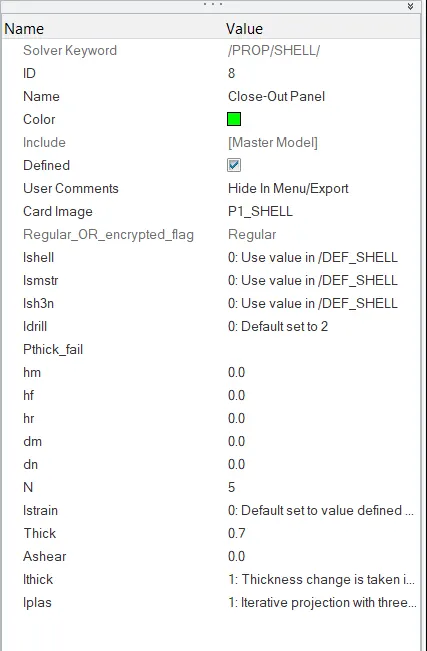
ANS:Now as per the question says that modification wouldn't be considered for simulation means the shell properties and the rest of the properties is not taken for modification ,HAT SECTION &CLOSE-OUT PANEL the default values images shown below:
After this we choose to go to analysis in order to do a simulation we choose RADIOS now we have to assign a path where we have save our all simulations,clicking on RADIOS our simulation gets started.

4. At the end of the simulation, do the energy error and mass error checks and determine whether results would be acceptable.
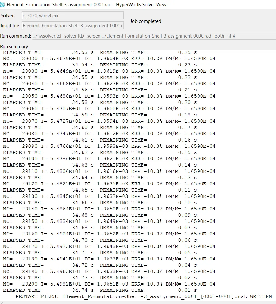
ANS:Taking all the defaults values into consideration and clicking on RADIOS simulation gets completed,so it is known to have a energy error to be considered ranges from -15% to 5% are acceptable ,below and above to the given ranges of error considered to do a rework on it or taken as wrong.
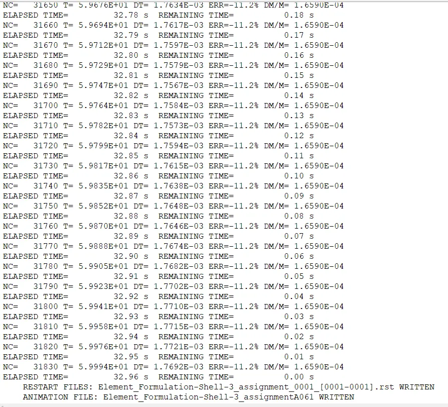
Here maximum eneregy error is -11.2% and mass error is 1.6590E-04 ,so the simulation of default values of error can be considered because it comes under the given range.
5. If acceptable, Plot rigid wall forces, internal energy, hourglass energy, contact energy, total energy of the simulations.
ANS:Now the steps are being followed ,firstly shifting hypermesh to hyperview mode and the loading a file which is H3D file of default values model can be loaded after that we go to hyperwork 2D where we can plot the different eneregy which is a graphical representation.
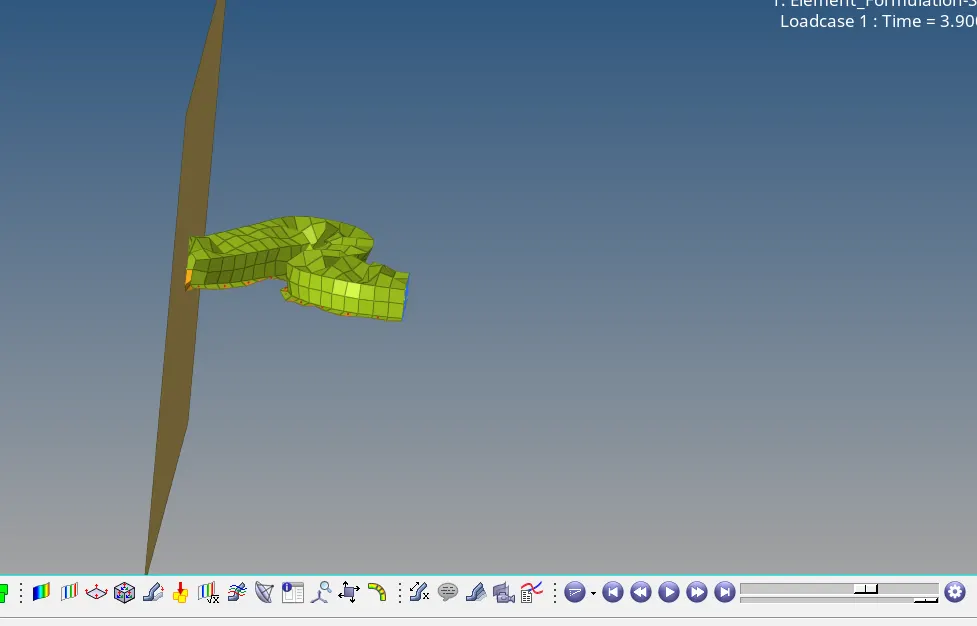
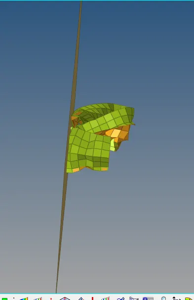
Firstly lets take a look of the model capturing in hyperview shown below:
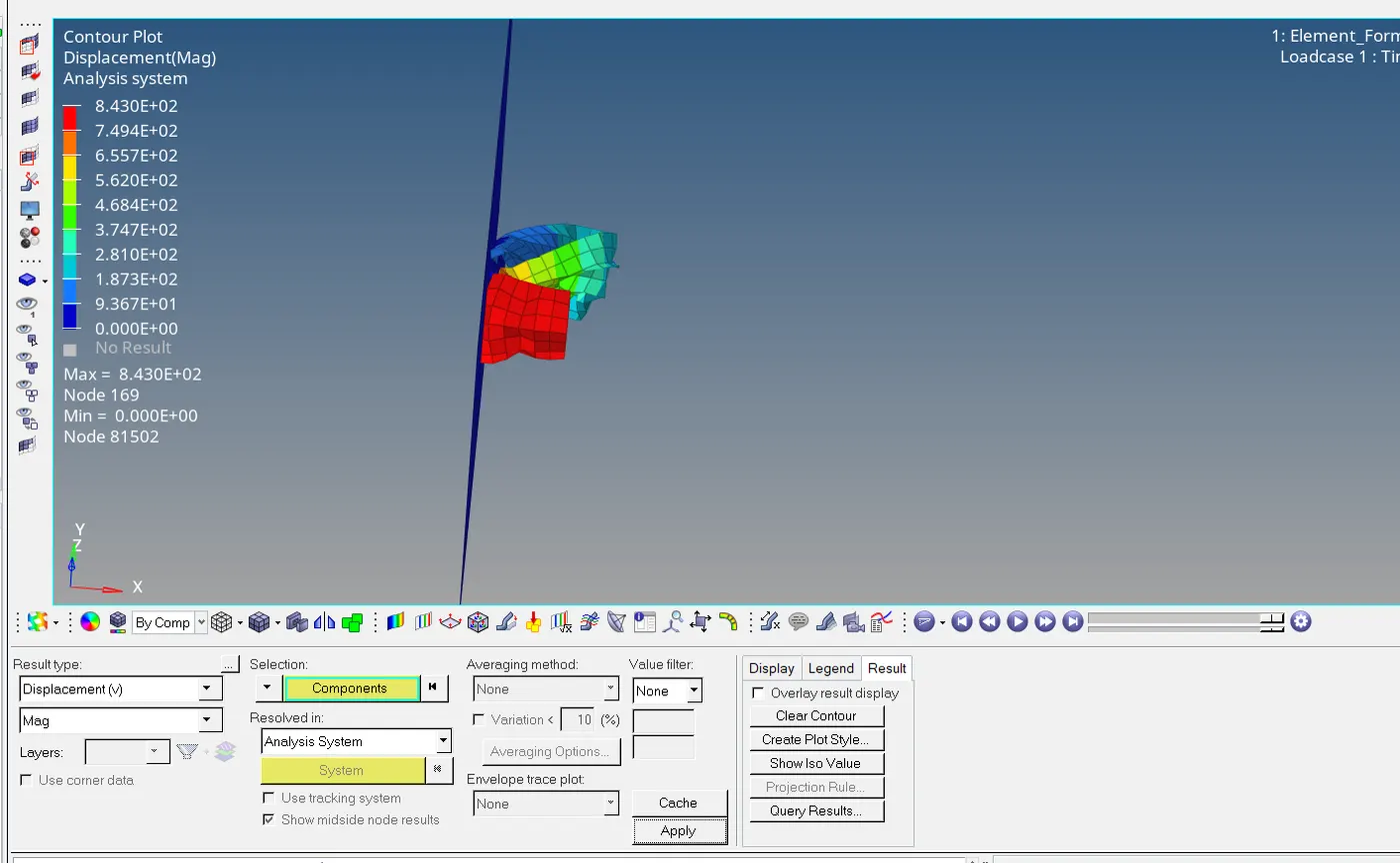
Now additionaly lets take look to model in contour model in which the ranges of values can be visualised are shown below:
(a)DISPLACEMENT CONTOUR PLOT:
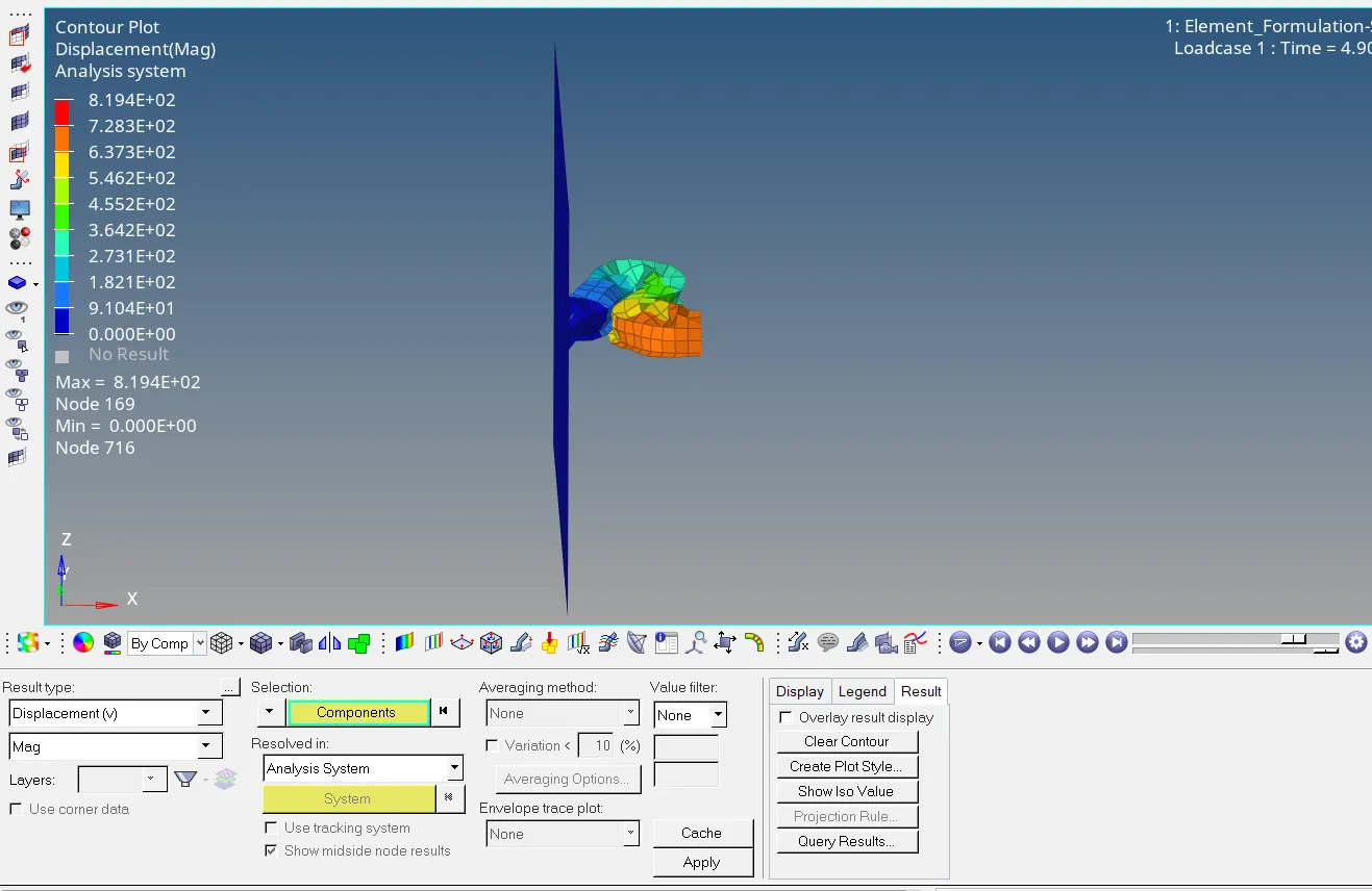
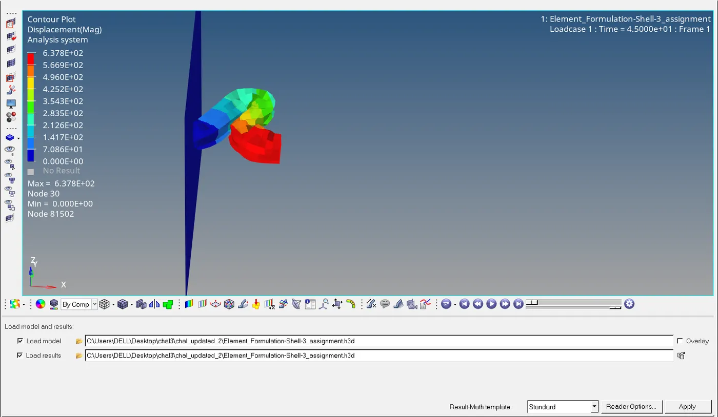
Changing in the colour signifies the displacement of deformed model.Then clearing the contour we gotta go for von-mises stress deformed model.
(b)VON-MISES CONTOUR MODEL:
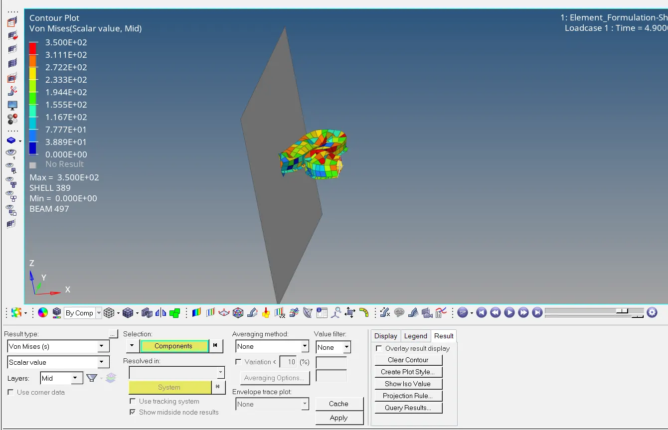
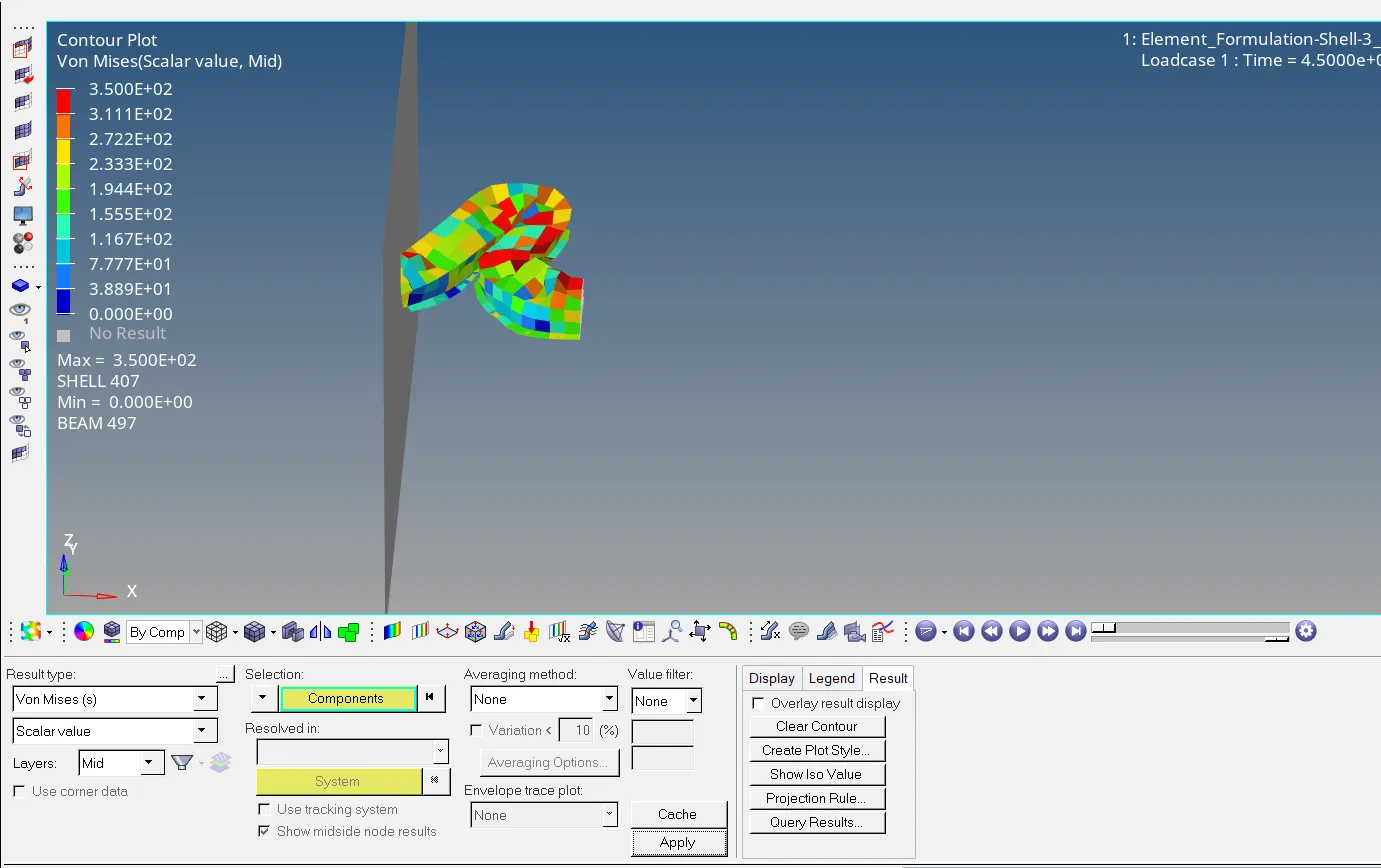
This variation signifies the variation of stresses on a different elements meaning here the stresses having there variation ranges.
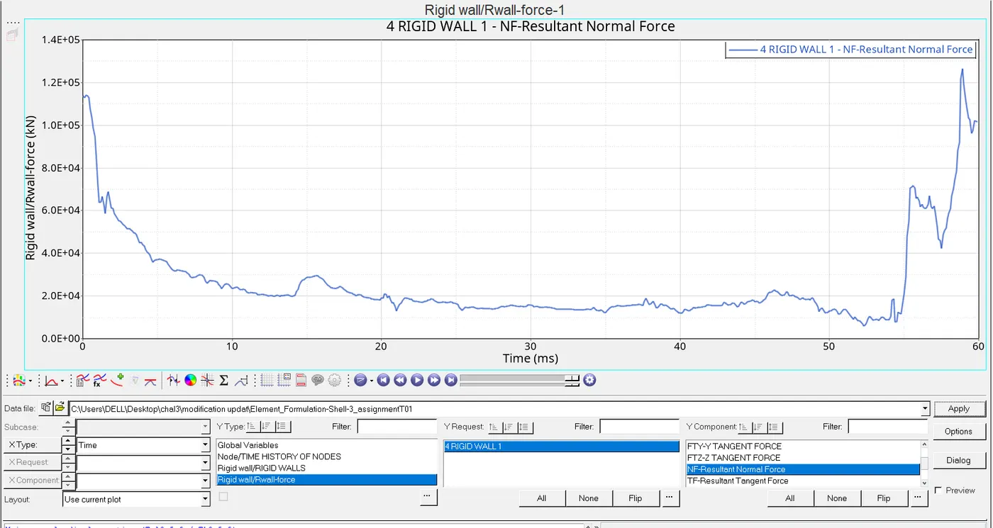
(c)PLOT RIGID WALL FORCES:
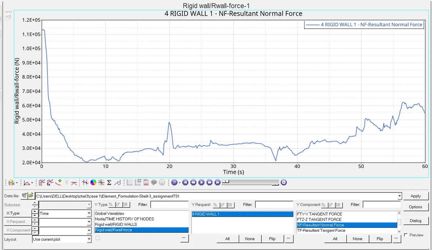
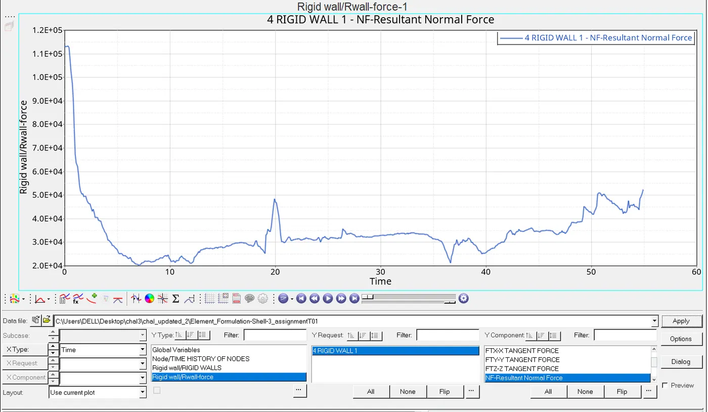
The graph shown above tells the variation in the forces.
(d)INTERNAL ENERGY:
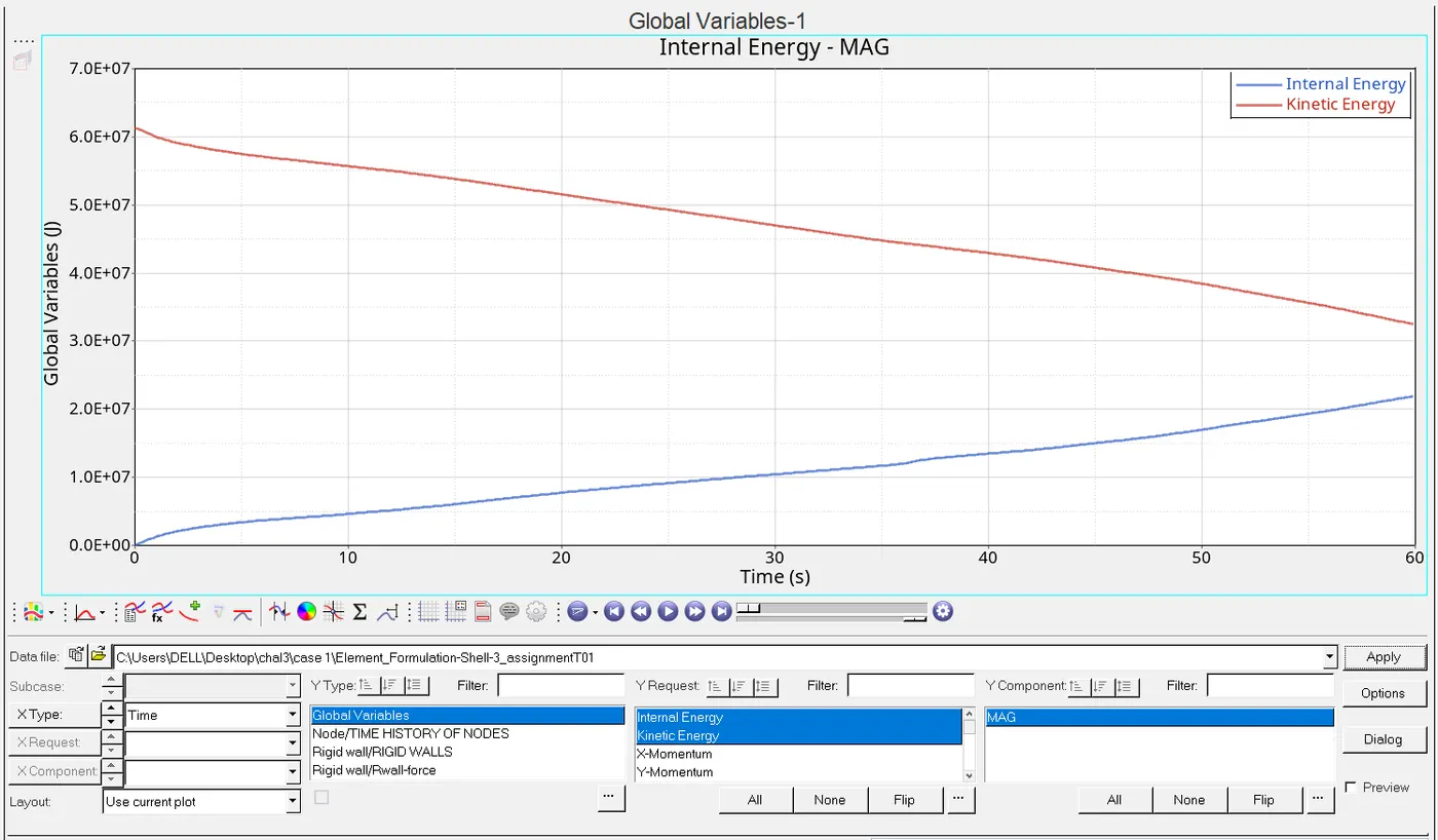
here the KE is keeps on decreasing parallelarly with the increament of Internal energy.
(e)HOURGLASS ENERGY:
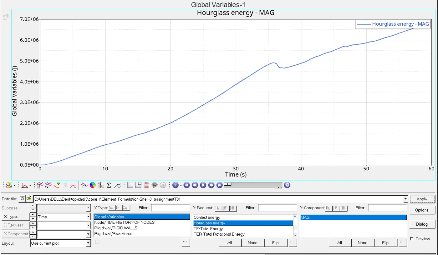
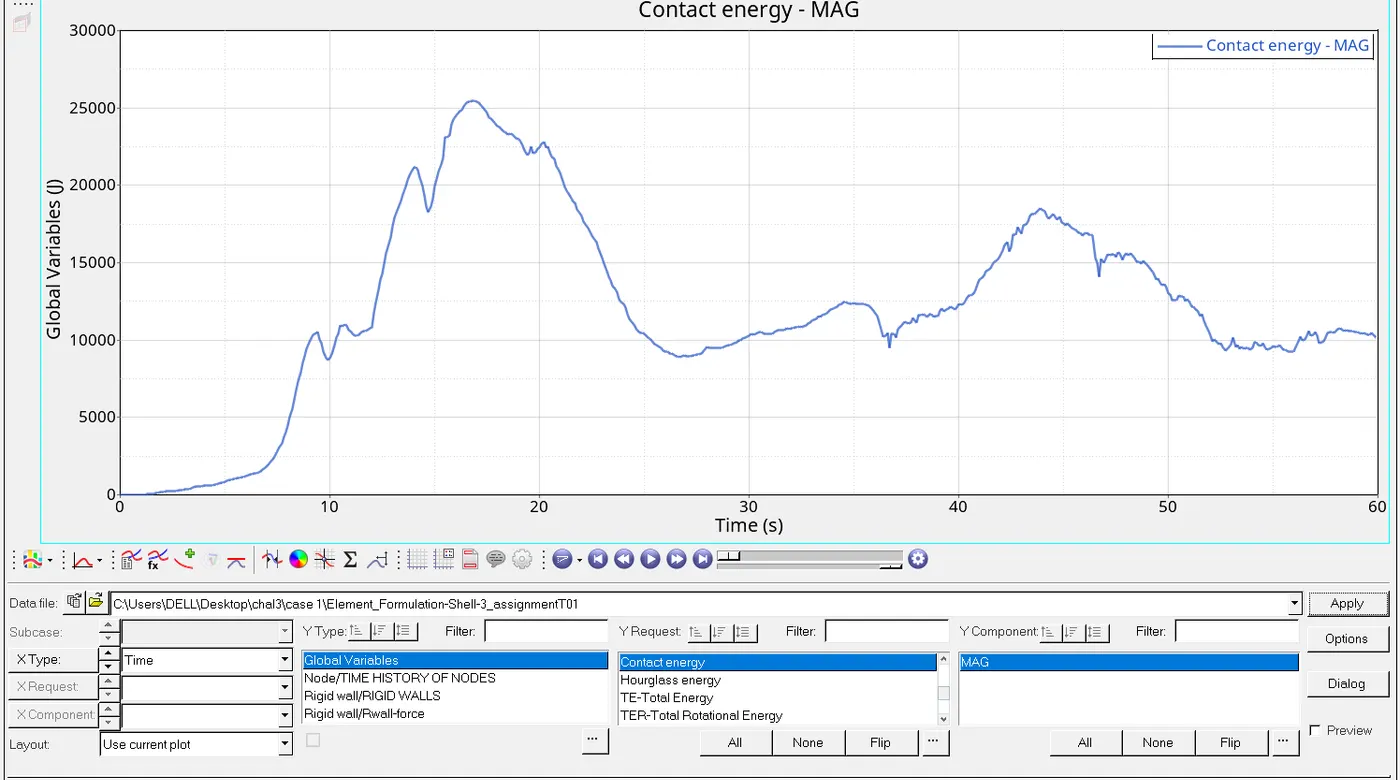
(f)CONTACT ENEREGY:
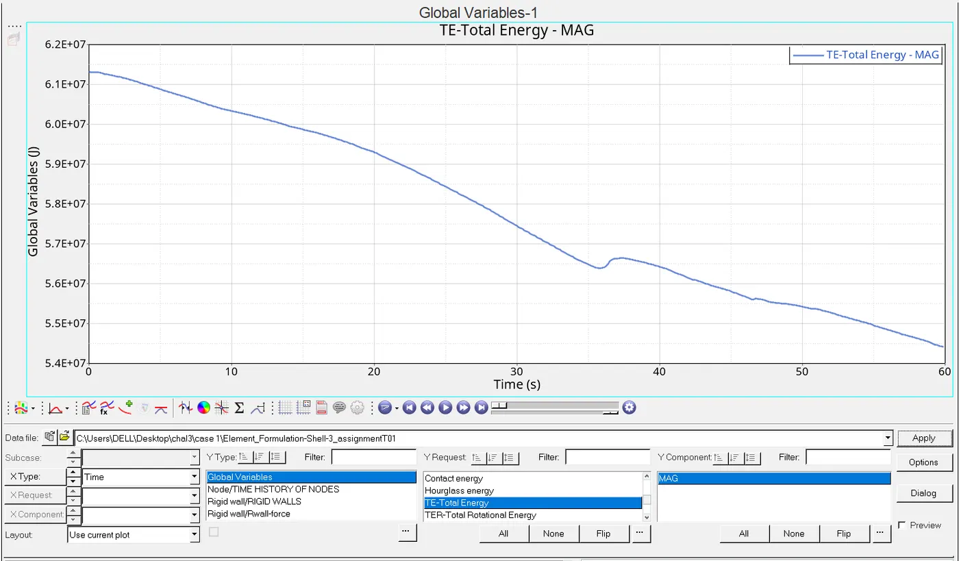
(g)TOTAL ENERGY:
6. Change all the shell elements properties to recommended properties, save this as separate, rad files and run the simulation.
ANS:Now we have some changes which is shown above now we gotta go for its simulation ,procedure are all same image shown the error of simulation with modification

7. Follow steps 5 and 6
Ans:The following steps are similar to what we have done previously will be done again with changed values of given model
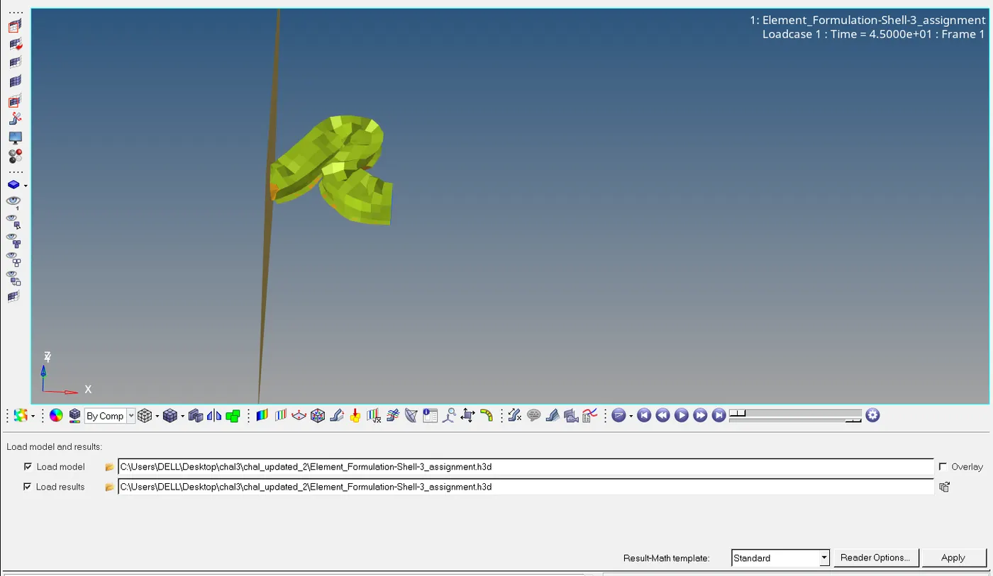
(i)The model which we have got in hyperview shown below:
(ii)Displacement and von mises model with changed values shown below:
(iii)Plot rigid wall forces, internal energy, hourglass energy, contact energy, total energy.
Ans:Shifting our mode to hypergraph 2D
(a) Total energy:
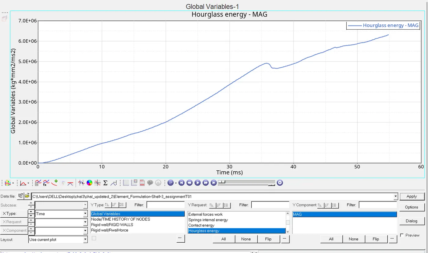
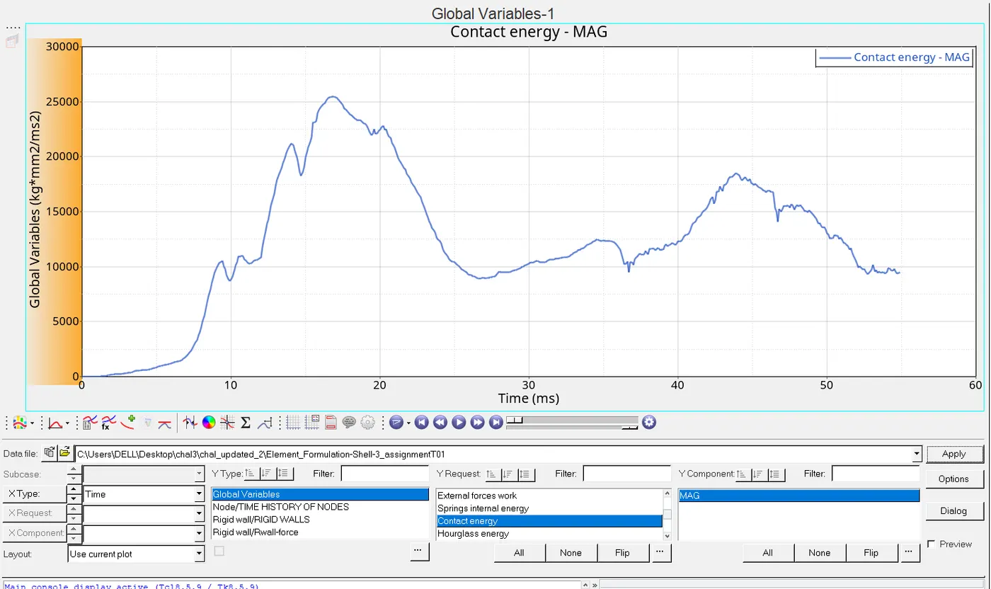
(b)Hourglass energy and contact energy:
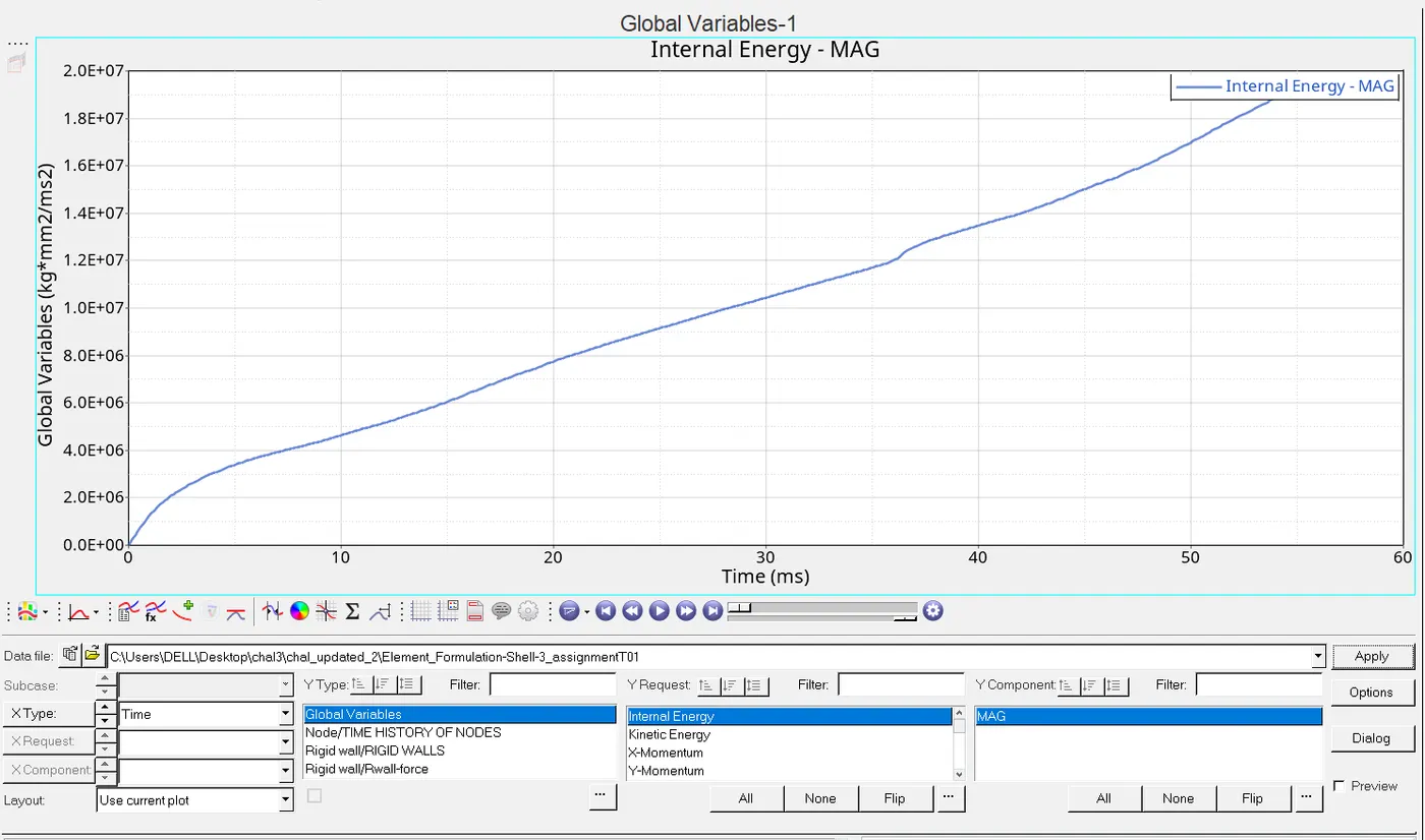
(C)INTERNAL ENERGY:
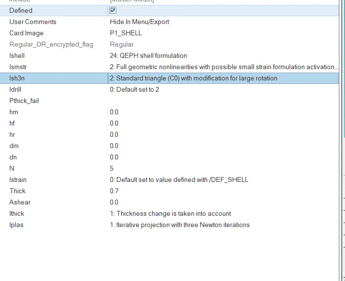
( 6 )and ( 7 ) now we go to change the property as shown below:
Simulation that we have got:
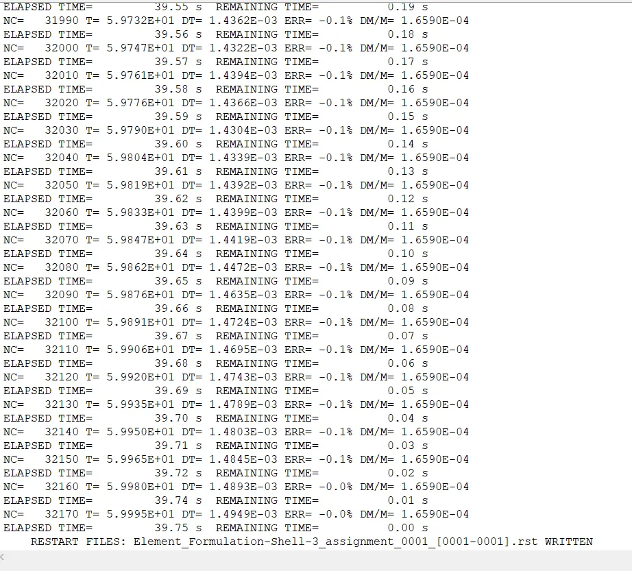

Now shifting the mode to hyperview and then hypergraph2D to watch the changes in the displacement and von mises also in different energies listed above:
Shifting it to contour mode to watch the displacement and von mises:
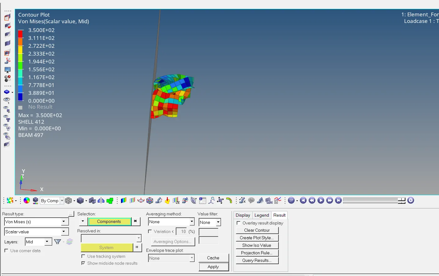
Now going to looking at the graph changes of eneregy:
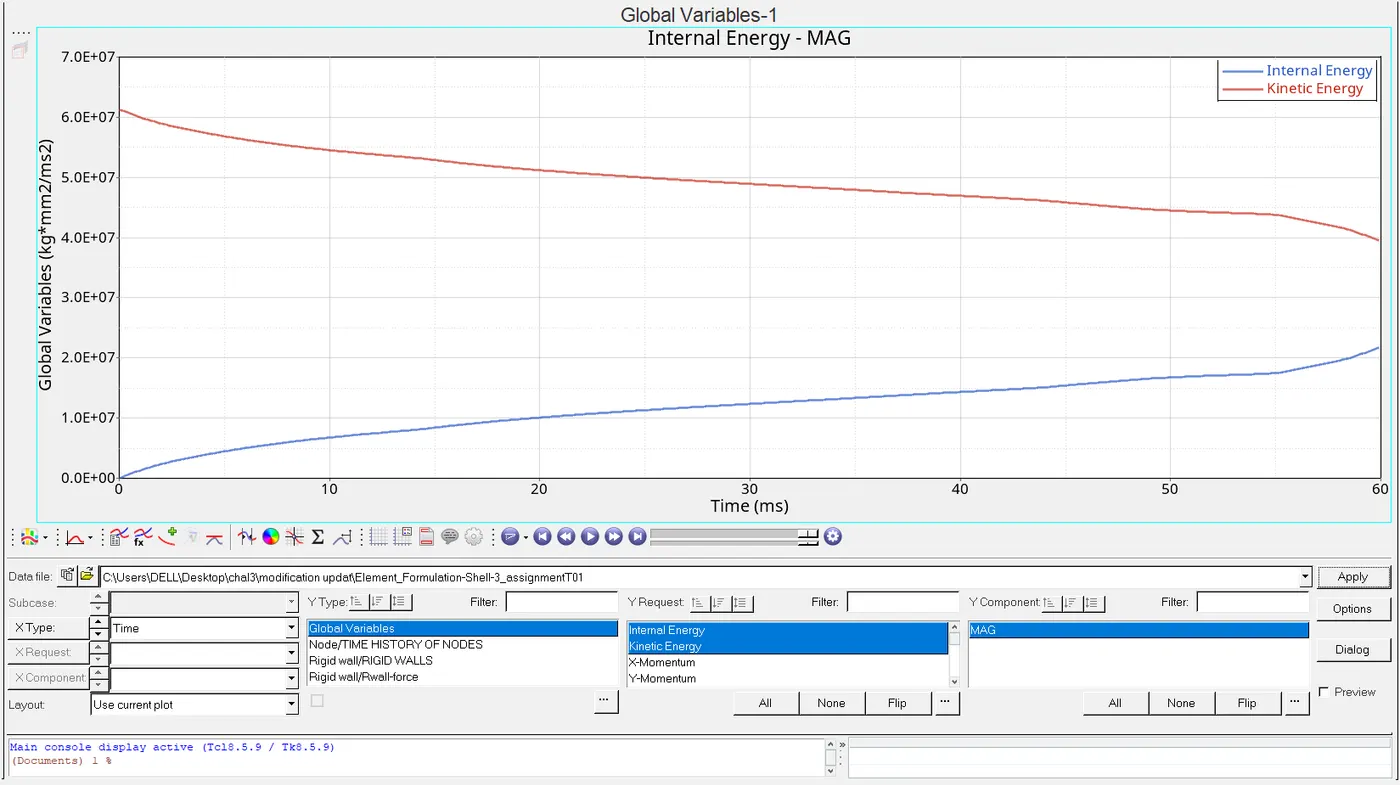
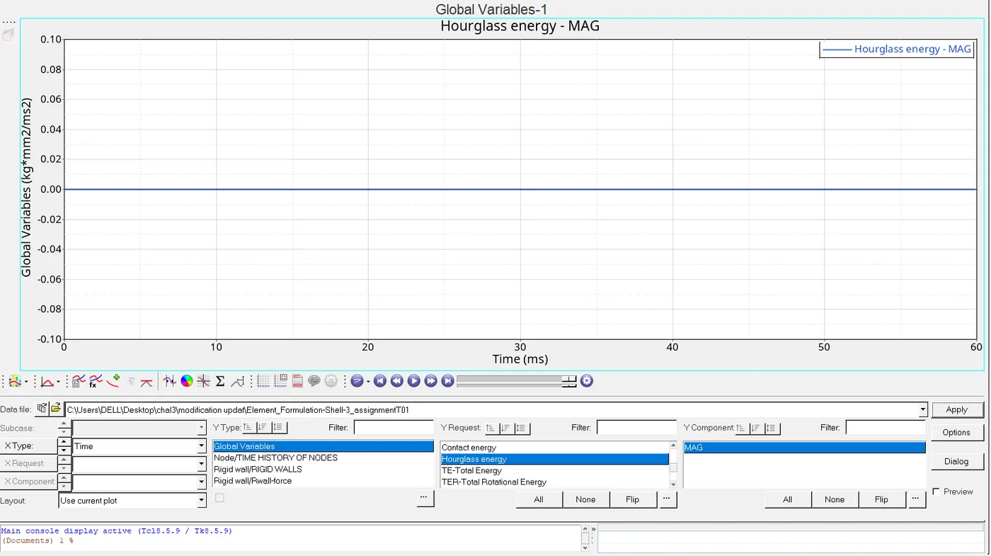
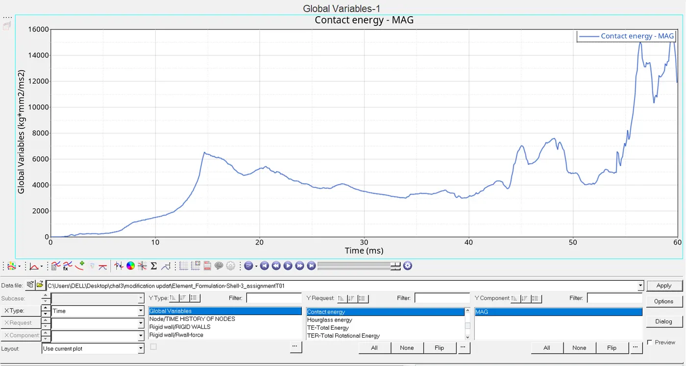
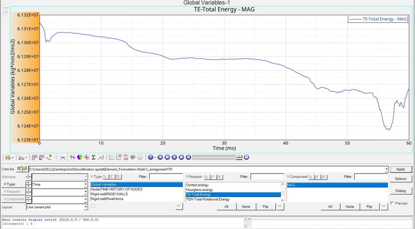
Here we have plotted by changing the properties of it.
8. Create a brief report comparing all the results from steps 5 and 6 for both simulations.
9. Comment whether there is any change in the results and why there is any change in the result.
Ans:(a)Let us talk about the displacement is uneven since we have the default values but have got evenness because we have used Qpeh.
(b)Stress of vonmises are quite high in default calculation and vice versa in modify model using Qpeh
(c)In the rigid wall we can't see any variation because crash beam criterion defines due to collision to wall ,that is why at starting it seems to be high after hitting it gets lower down irrespective any property changes in it.
(d)Internal energy is due to internal pressure in the material generates the stress which generates straining effect so from this we can say increament in stresses results in inclining of internal energy which is happened in both the model(i.e unchanged & modified) .
(e)In hourglass we haven't used any properties in the default values so it is keeps on increasing with time while introduction of properties in the next model we have seen constant line of projection occur.
(g)Contact energy keeps on increasing rapidly under the shell element contact continuously results in decreament in default model and in case of modify model increament is not that high due to Qpeh and it also get decreased due to the same region stated in default model.
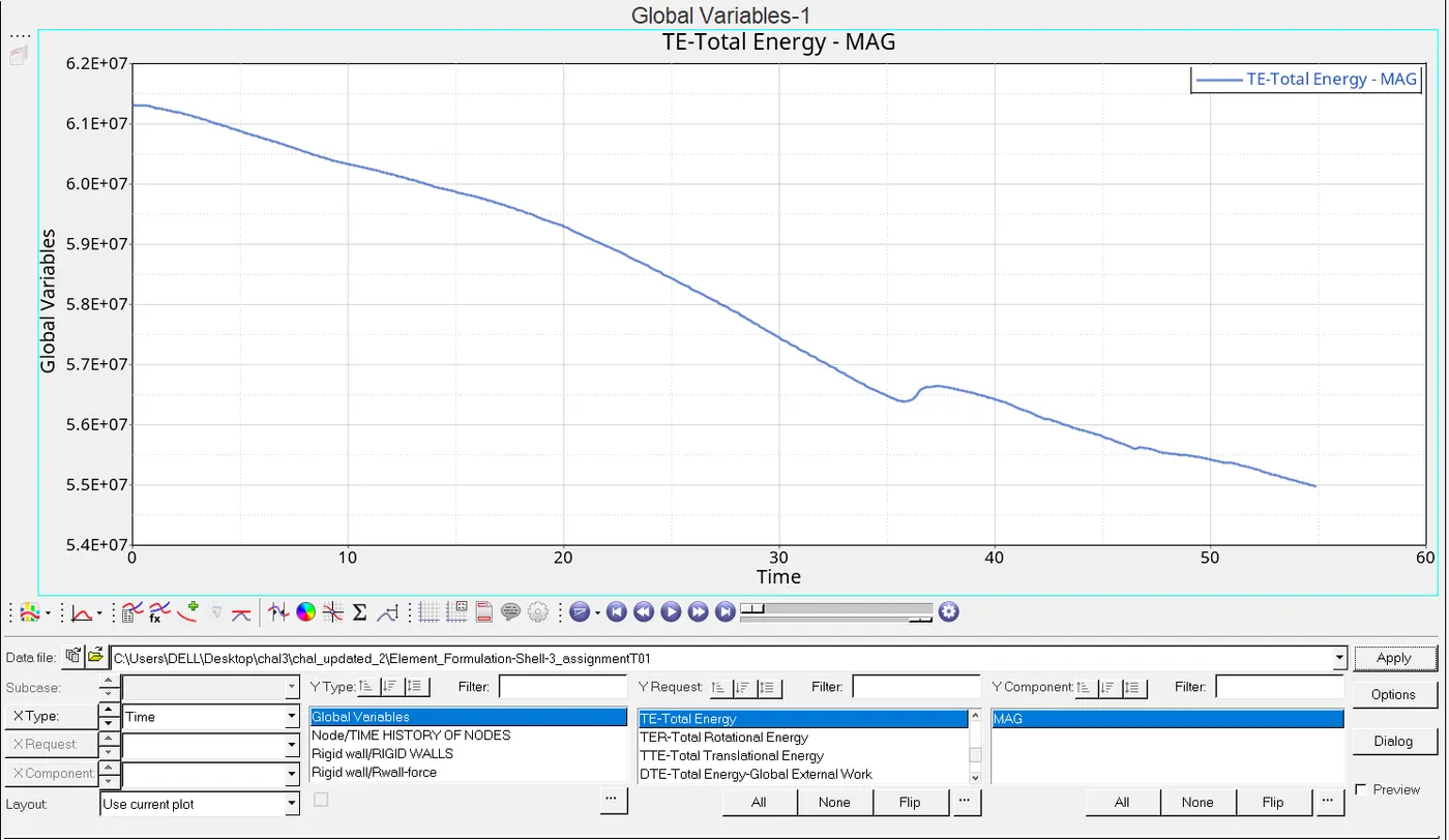
(h)TE keeps on decreases due to decreament in KE because decreament of mass in default model,in modified model it decreases not very rapid due to Qpeh.
CONCLUSION:Qpeh plays a vital role to control the energies it doesn't let the energy to go to high or to low.
Qpeh reduced the shell formulation energy error upto the great extent which has been seen in the above cases.Also the positive in the energy error signifies that energy is being created in the model which shows the model error or in standardised way it should be in between +5%to-15%.