Assignment 3-2D Element Formulation Challenge
aim: Comparison of results with base simulation and improved shell element properties
Element Formulation:
In fae an infinite component is divided into smaller more easily mappable component. This resultant depends upon the type of the component. the cae has 3 element namely 1d 2d and 3d. the formulation of the element means giving the element an outline as how they are supposed to work when put under different condition.every element type has a specific recommended formulation for optimum working.
1d Element Formulation:
1d element are formed one there only node to node connection. they only have one significant dimension.
formed for node to node.
one dimension largely greater than the other two.
- cross sectional area assumed to constant
- eg : truss, beam, spring
types of 1d element formulation
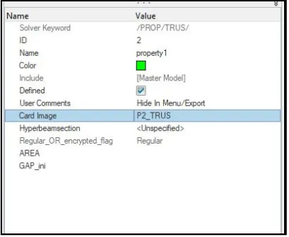
1. /prop/type2 or /prop/Truss
- Similar to beam.
- Can transmit only axial forces and no bending.
- Only translational motion.
- Elastic and elastoplastic material can be used for them.
- truss area, cross section shape, gap_ini should be provided by the user.
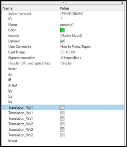
2. prop/type3 or prop/Beam
- has 6 dofs(3 translationa and 3 rotational).
- can have any spatial orientation.
- node 1 and node 2 defines the length and node 3 defines the cross sectional orientation.
- the dofs are to be checked as whether they are free or constrained.
- inertia is optional.
prop/type4 or /prop/spring
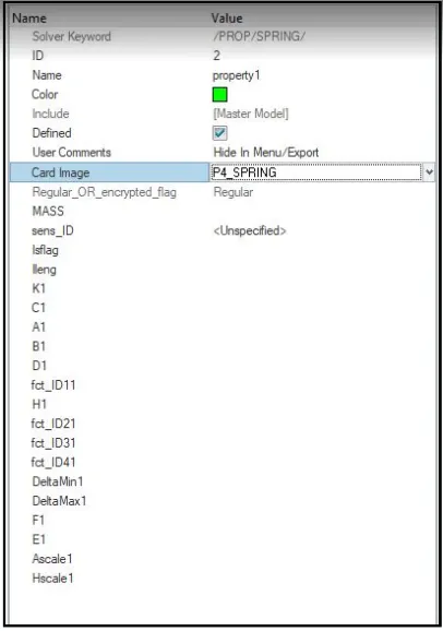
- mass,stiffness and damping has to provided by the user.
- H1 is the variable dealing with the non linearity.
- fct_ID11 to fct_ID41 deals with curve which define the behaviour of the spring
2d Element Formulation:
- also known as shell elements.
- combination of membrane and plate elements.
- every individual node has 6 dofs.
- used on components havi thickness below 6mm.
- airbages, sheet metal components , automobile frames etc.
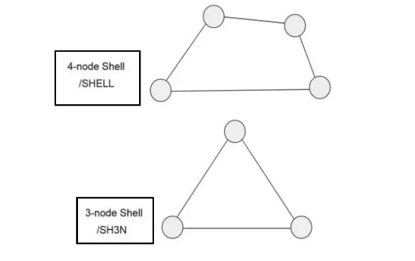
- can be divided into: a) 4 node shell b) 3 node shell
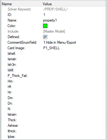
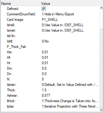
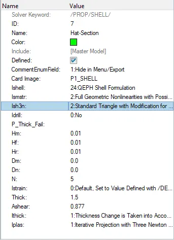
The image below shows us the parameter that the user should provide for the elements to work according to real life counter part when put into similar conditions. The
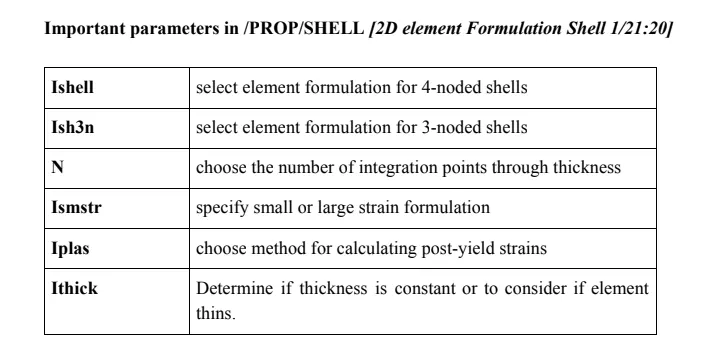
- Ishell: Shell small strain formulation flag
- Ishell=1,2,3,4 (Q4): original 4 node Radioss shell with hourglass perturbation stabilization.
- Ishell=24 (QEPH): formulation with hourglass physical stabilization for general use.
- Ishell=12 (QBAT): modified BATOZ Q4γ24 shell with four Gauss integration points and reduced integration for in-plane shear. No hourglass control is needed for this shell.
- Ishell=2 is incompatible with one integration point (through thickness) for shell element
- Ish3n: i. For tria elements with modification for large rotation.
ii. 1 integration point
iii. low cost.
iv. No hourgass deformationn - N:
i. Only integer value can be provided.
ii. Has a range of 0 to 10.
iii. 5 is the most common number of integration points.
- Ismstr:
i. Small strain formulation is activated from time t=0, if Ismstr =1 or 3. It may be used for a faster preliminary analysis, but the accuracy of the results is not ensured.
ii. Any shell for which Δt<Δtmin can be switched to a small strain formulation by Radioss Engine option /DT/SHELL/CST; except if Ismstr =4.
iii. If the small strain option is set to 1 or 3, the strains and stresses which are given in material laws, are engineering strains and stresses; otherwise they are true strains and stresses.
iv. Ismstr =10 is only compatible with these material laws 42, 62, 69, and 82 that use total strain formulation. Generally, the Left Cauchy-Green strain is used. For User laws, the deformation gradient tensor and the right stretch tensor could be used.
v. Ismstr = 2 is recommended as it allows the strain formulation to switch between large and small strain theory according to the situation.
- Iplas:
- Ithick:
Importing the solver deck
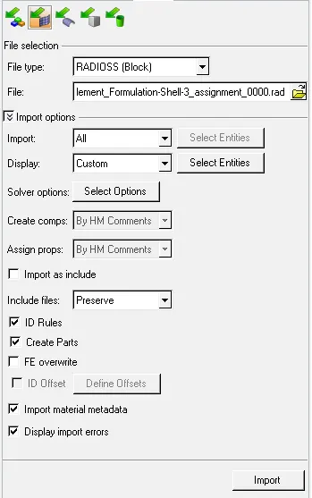
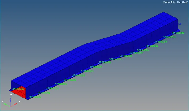
the model is imported as below
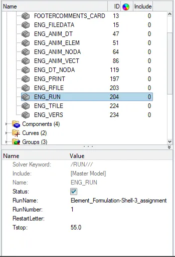
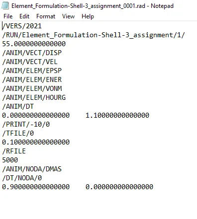
1. change the run time to 55 ms.
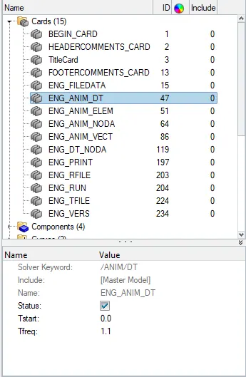
2. Change the number of animation steps during simulation to a minimum of 25 and maximum of 60.
selecting the number of animation between 25 and 60. selecting 50
Tfreq= time step/no of animation
= 55/50
= 1.1
keeping the default values for the property card
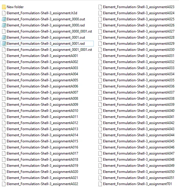
Now we will run the simulation. Analysis -> Radioss. selecting the required 0000.rad file in the inut file dialog box.


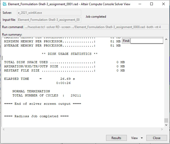
verifing the tinestep and animation time has been changed
checking the energy error is within the acceptable tolerence of -15% to +5%

Energy error: -10.3%
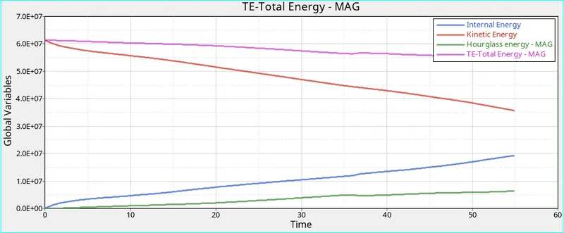
Internal Energy: 0.1932E+08 gm^2/s^2
kinetic Energy: 0.3563E+08 gm^2/s^2
since the result are within the acceptable range we will plot the graphs of the following criteria
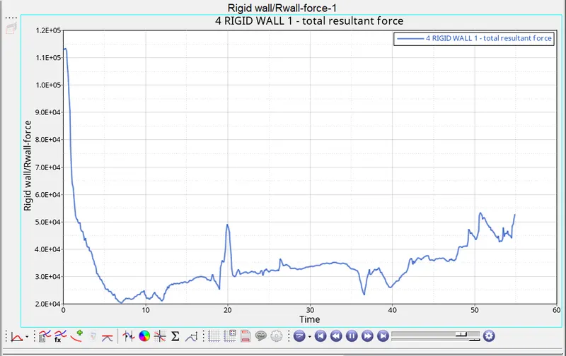
- Plot rigid wall forces
- internal energy
- hourglass energy
- contact energy
- total energy
opening hypergraph and loading the h3d file of week 3 assignment

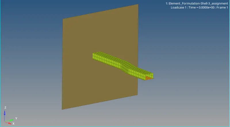
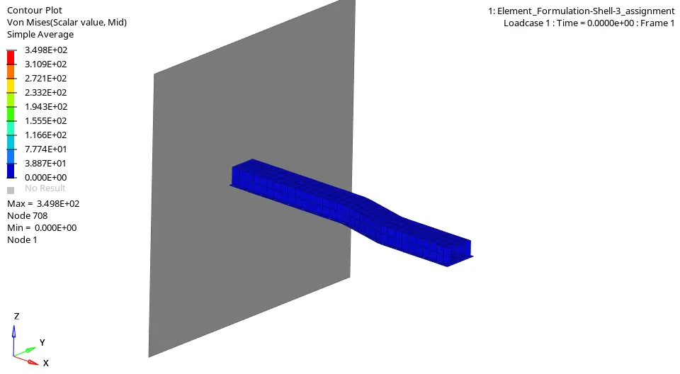
Now we will apply contour to the rail. Contouring helps us to realise the intensity of specific parameter on individual elements and on the component as a whole. In contouring value of the parameters corresponds specific colour. we can say that specific colour corresponds to a range of value.
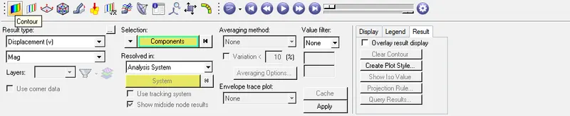
The above shown image shows the dialog box of contour we have to select what parameter whose behaviour we want to see in the result type, select the component the selection dialog box and averaging method
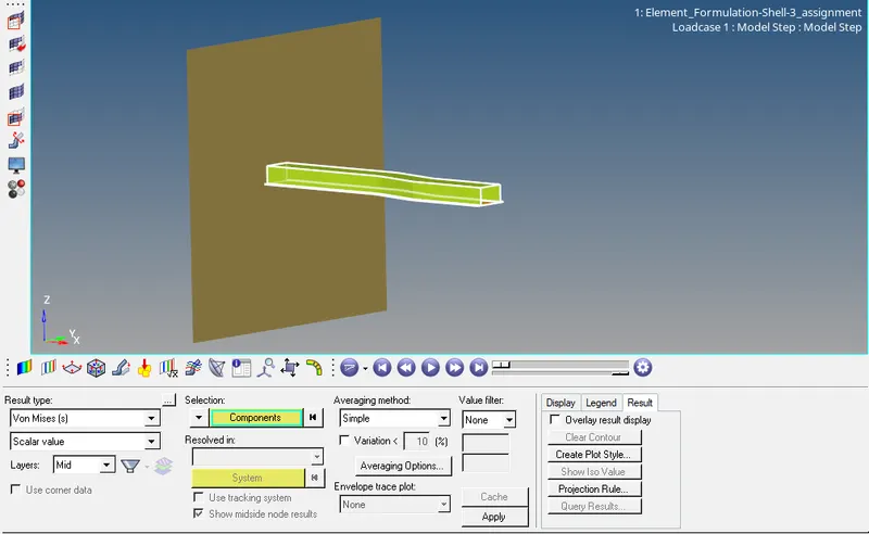
Result type: Von misses stress
selection(component): 1.Hat section 2.Close out panel
Averaging Method : Simple
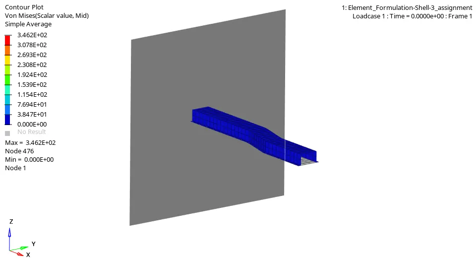
After applying the contour the next step is post processing

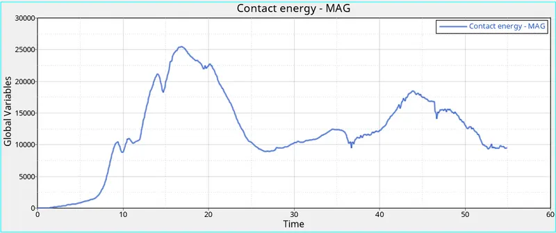
case 2 :
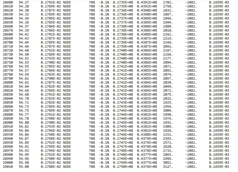
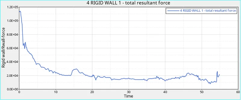
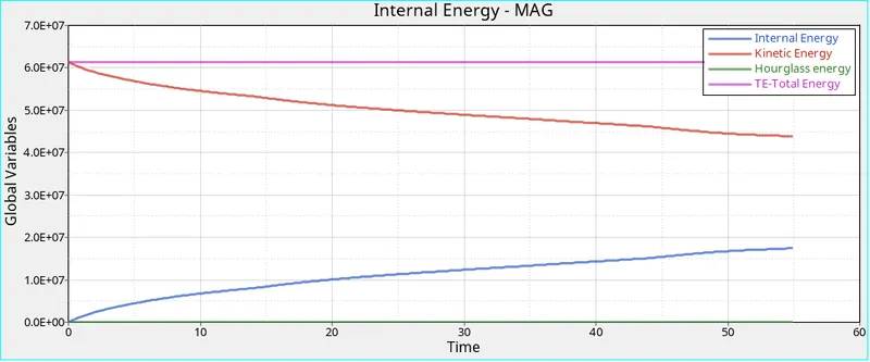
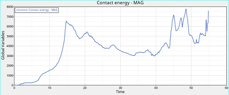
| CASE 1 | CASE 2 | |
| Maximum Energy Error | -10.3% | -0.1% |
| Maximum kinetic Energy | 0.3563E+08 | 0.4376E+08 |
| Maximum Internal Energy | 0.1932E+08 | 0.1750E+08 |
| Hourglass Energy | `~~` 6.3E+06 | 0 |