Assignment 3-2D Element Formulation Challenge
OBJECTIVE:-
- Comparison of results with base simulation and improved shell element properties
PROCEDURE:-
CASE 1:- WITHOUT ASSIGNING THE RECOMMENDED PARAMETER IN THE PROPERTY
- Import the model in the RADIOSS user interface.
- Import the file as SOLVER DECK.
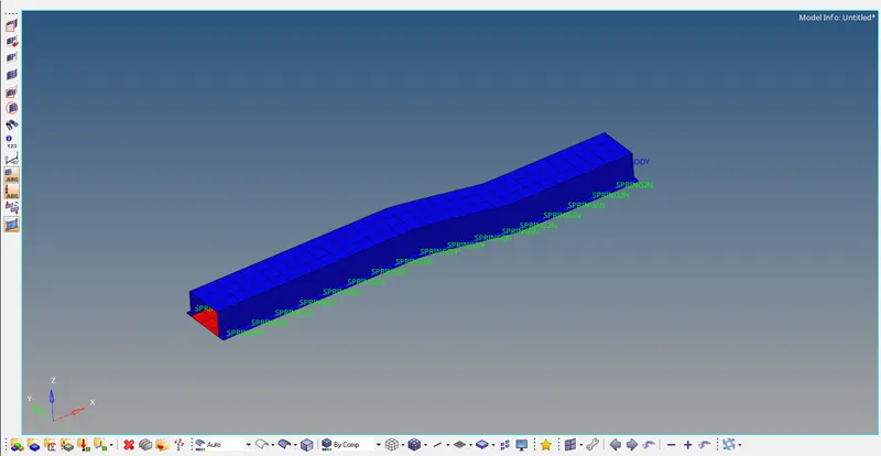
- The model will look like this.
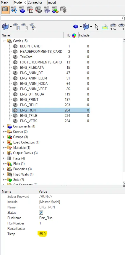
- Now next step is to assign the value of the time step in ENG_RUN cars as 55ms as per the question.
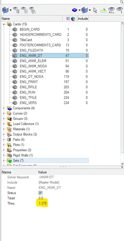
- Now we have assigned the number of animation steps. I choose 40ms as the number of animation steps as per the question.
- Tfrequency= TIME STEP/NUMBER OF ANIMATION STEP = 55/40 = 1.375.
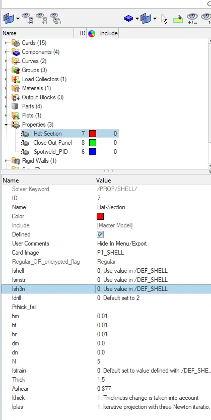
- In the property card, every parameter property is by default shown below.
- Now we will run the simulation ANALYSIS-RADIOSS.

- In the RUN OPTION panel it is recommended to write -nt 4. not stand for number thread is assigned to do the simulation at a faster rate.

- Click RADIOSS and it will show JOB IS COMPLETED
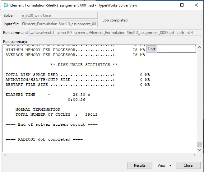
- Now click on RESULT, it will directly take you to hyper view where we can see the animation of the simulation. Animation files are in name of h3d.

- Click apply
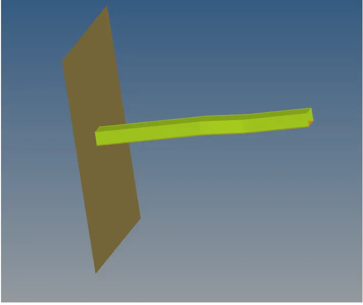
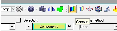
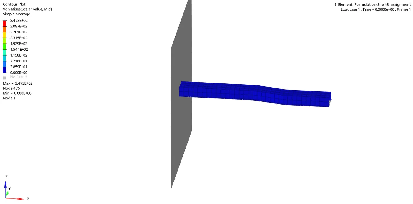
- Now switch to contour mode
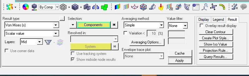
- After switching choose the RESULT TYPE to see the deformation. I choose VON MISSES and click apply.
- we can see the animation.
- Now we can see the output of simulation in 0001.out file
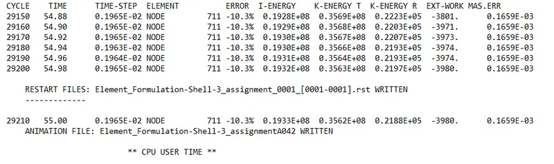
SAFE TOLERANCE IS -15% TO +5%
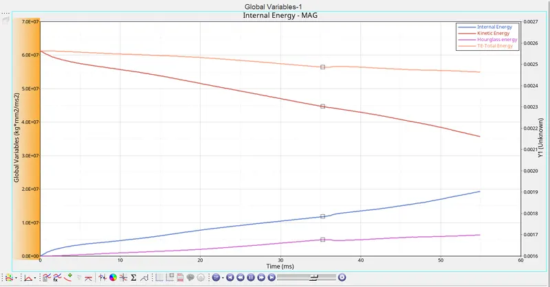
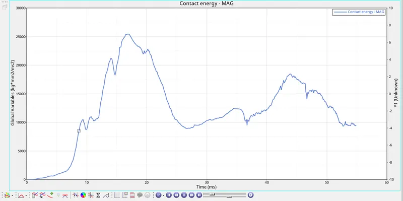
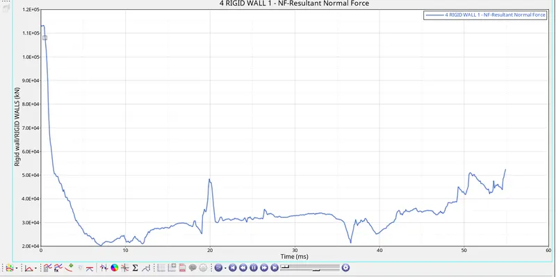
- Graphs for plotted for this various energy. For plotting the graph, we have to switch to the hypergraph tab and import file T01 which is stands for time history.
CASE 2:-- ASSIGNING THE RECOMMENDED PARAMETER IN THE PROPERTY
- Assign all the parameter property
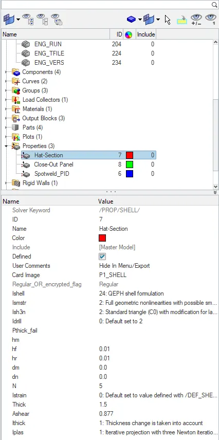
- After assigning run the simulation same as above simulation
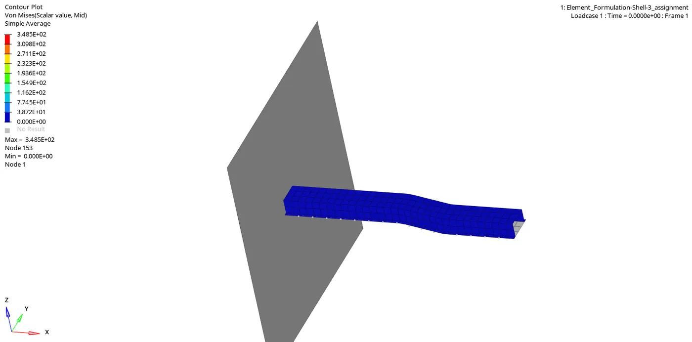
- von misses deformations is
- Now we can see the output of simulation in 0001.out file
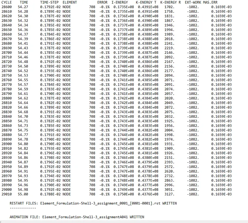
SAFE TOLERANCE IS -15% TO +5%
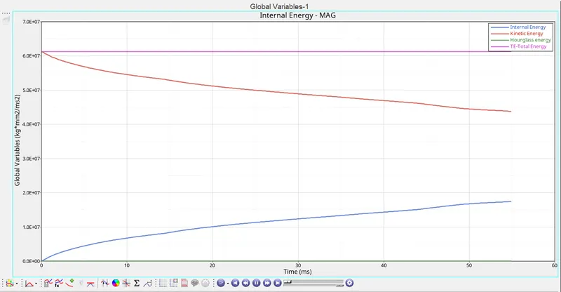
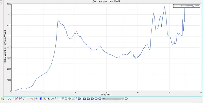
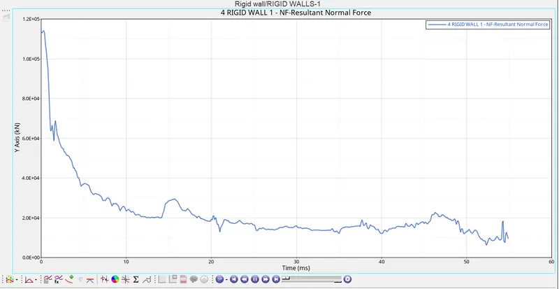
- Graphs for plotted for this various energy. For plotting graph, we have to switch to the hypergraph tab and import file T01 which is stands for time history
COMPARISON BETWEEN THE CASE 1 & CASE 2:-
| Basic for comparison | Case 1 | Case 2 |
| obtained maximum energy error | -10.3% | -0.1% |
| obtained maximum kinetic energy | 0.3563E+08 | 0.4377E+08 |
| obtained maximum internal energy | 0.1932E+08 | 0.1750E+08 |
| Requirement of hourglass energy | It requires hourglass energy to the energy balance | no hourglass energy is required to balance the energy |
| Results | The results are less accurate | The results are accurate |
Hourglass energy:-
- In FEA, the hourglass model is also known as the "zero-energy mode" because the deformation energy of elements under the hourglassing mode is zero. But the hourglass
- energy is not equal to zero.
- In a shell element which have a number of integration points, for reduced computation effort, a reduced integration that uses a single integration point is used.
- In such cases, the deformation mode from the analysis results will be false. This is called the hourglass phenomenon.
- This is just a non-physical zero-energy mode which leads to excessive element distortions.
- The more structured and less distorted your elements are, the better the results.
CONCLUSION:-
- Learned how to carry out the simulation.
- Learned about property cards.
- Learned how to use hypergraphs.
- Leaned about hourglass and how to remove these.