Assignment 2-RADIOSS Engine File Editing & 3D Meshing Challenge
1.calculate the speed of sound in steel rail:
C= `sqrt(E/rho)`
E : Youngs Modulus(Pa)
`rho`: Density(kg/`m^3`)
C = `sqrt((2.1xx10^5)/0.0078`
= `5,188.745m/s`
the speed of sound in steel rail = `5,188.745m/s
2.calculate the time takes for a shock wave to travel from one end of the rail to the other:
time =`(distance) / (time)`
=`1000/(5,188.745)`
=0.1927`s
3.Time for sound to travel length of rail= 0.1927`s
4.Edit the engine file so that the stress wave can be monitored.
there are 2 types of files any radioss solver will have for any analysis namely
Starter File
Engine File
Starter File:
starter file basically the file which contain all the inputs which you put into the model. it is also known as input deck. it contain all the inputs such the no of the nodes/elements no of the components, material laws, connections, boundary conditions. it is named according to the name the user has saved the model.
the strater file has many sub files or parts known as input blocks. Its syntax is 0000.rad.
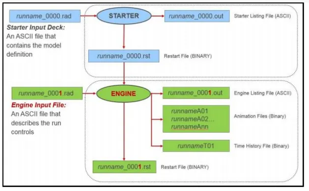
Engine File: Engine file contains the instruction and outputs animation requirements asked by the user. Syntax of the engine file is 0001.rad.
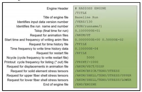
PROCEDURE TO EDIT THE ENGINE FILE
Import the radioss file named FIRST_RUN_0000.rad.
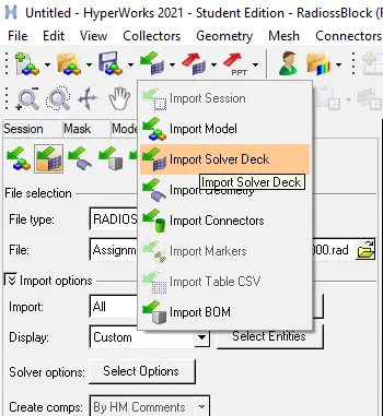
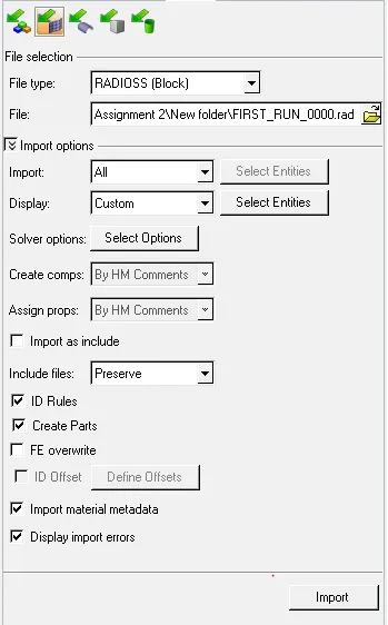
selecting the file type as radioss and browsing the file and clicking import
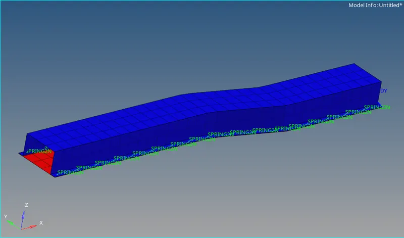
the imported model will be displayed.
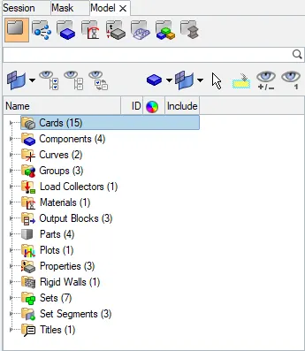
now to change engine file we have to edit the particular card which corresponds to the entity we have to change
the card are present in the model browser in the card component.
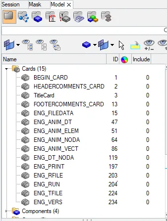
termination time equal to the time it takes for the sound to travel the length of the rail
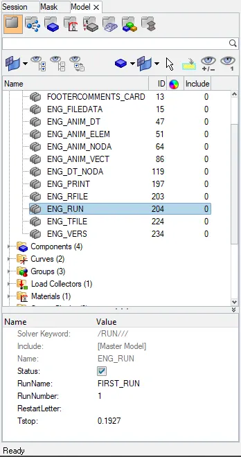
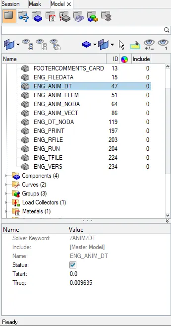
5.Set the frequency of animation output to a time that will give 20 animation steps(/ANIM/DT)
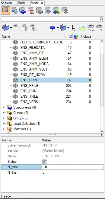
6.Change /print -10
now that we have assigned the recommended values for the entities we can run the analysis/simulation and look at the output.


we will run the analysis by clicking on the radioss button
After running the analysis we will look into the rad file to verify if the changes made is actually reflected in the model
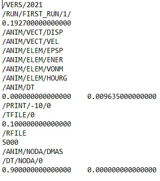
as we can sww the total run time of the simulation is equal to the time(0.1927s) taken by the sound wave to transverse the length of the rail.
the animation frequency has been set such that there will be 20 animation by the time sound travel the entire rail(0.009635).
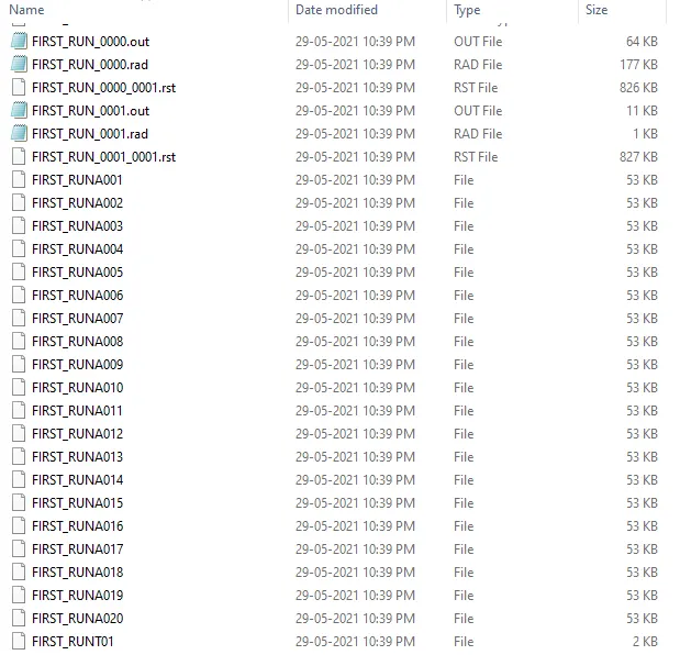
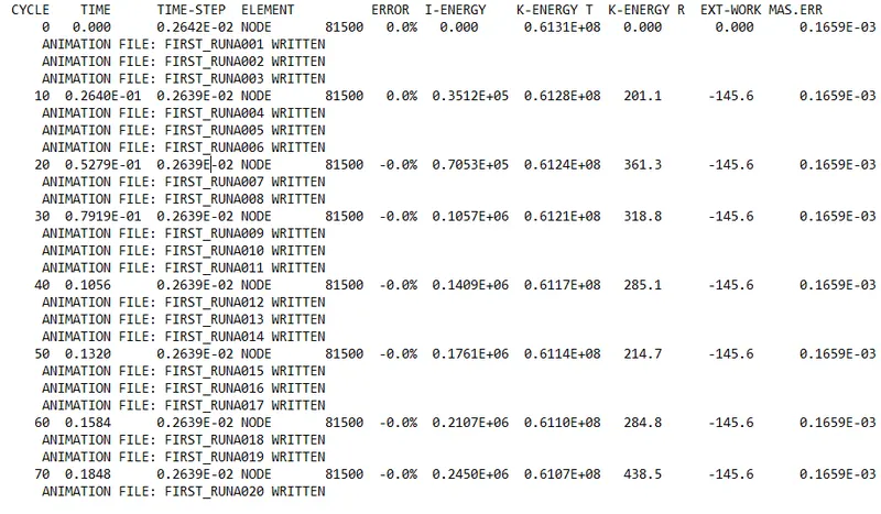
the cycle has been change to a have a intreval of 10
3d meshing tetra mesh and hex mesh
- Repeat class examples and, maintain the quality.
- Target tet size=5mm,hex size=10mm,tet collapse=0.15.
MODEL 1
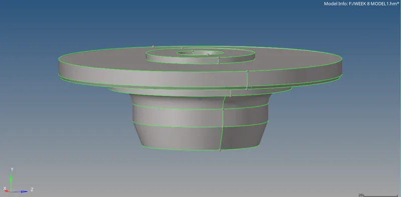
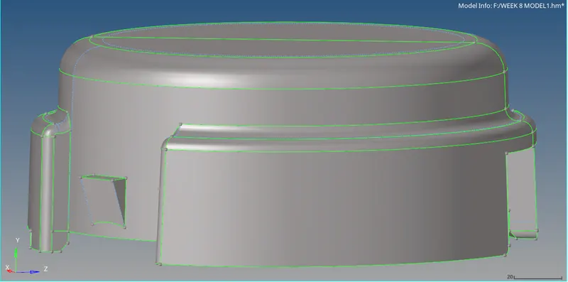
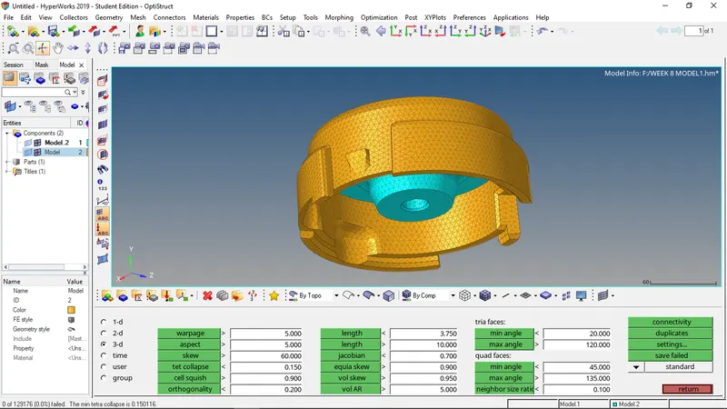
the first model is a housing model.the first step is to do some simple geometry cleanup required to achieve the proper clean surface to achieve a good mesh.toggling of the edges to avoid min length failure are the only geometric cleanup required for this model. the following images shows the cleanups done.
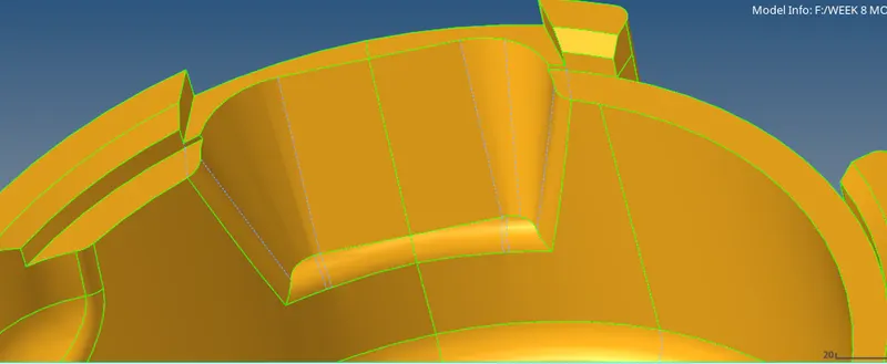
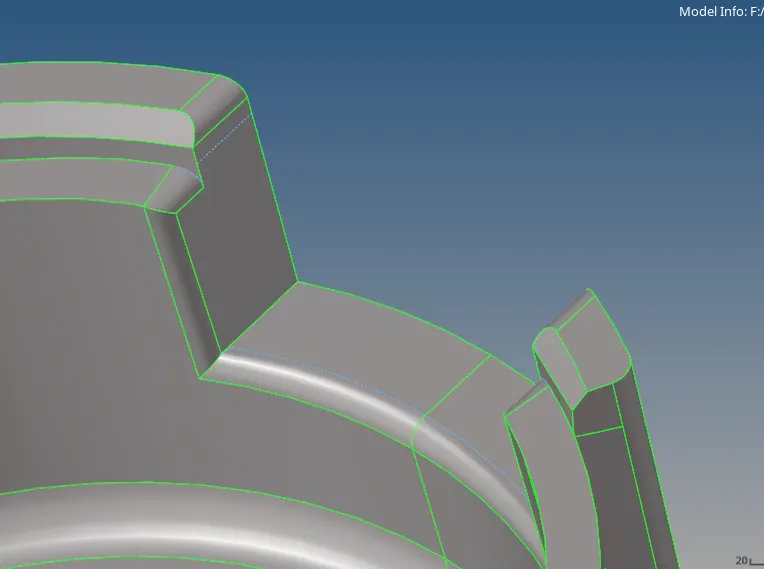
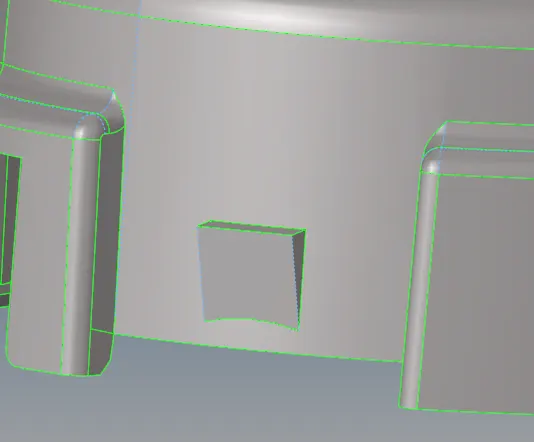
now we will shell mesh the components with target element size 5. the failure occuring will be max length and very few min length. these erros can be easily resolved by using optimizing tool in quality index
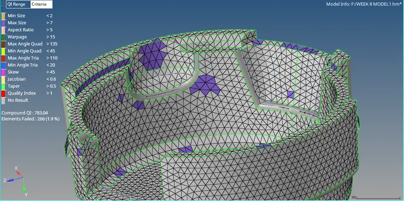
after solving these errors we can proceed to do the 3d mesh.
to perform the 3d mesh we have to go the 3d mesh option in the panel. In the 3d menu we have to select tetramesh option 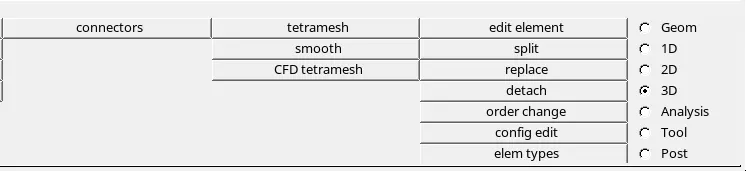
in the tetramesh menu we will have 4 options, we have to select the first option. first we have to change the comps to elements we can be achieved by clicking the inverted triangle and selecting the element from the ensuing dropdown dialog box.
we have have to select the entire elements encompassing the comonents.

now to go the tetramesh parameter option to provide the inputs required to give a better mesh

providing the min, max element sizes, and tet collapse. after doing that we will go to the tetramesh and click mesh. hypermesh would create the 3d mesh according to the quality criteria.
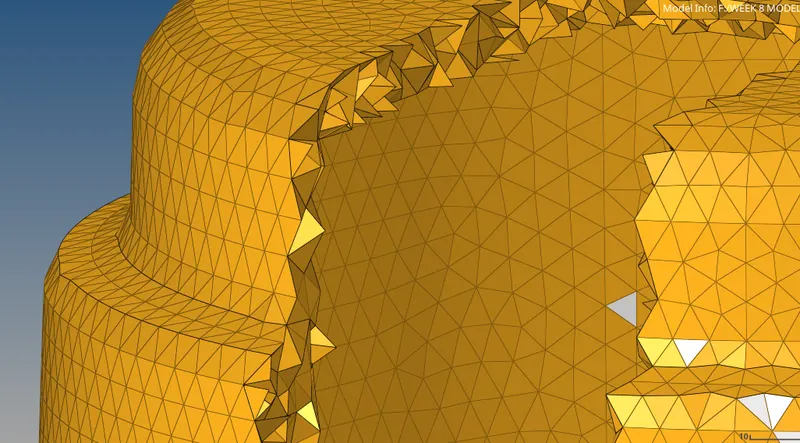
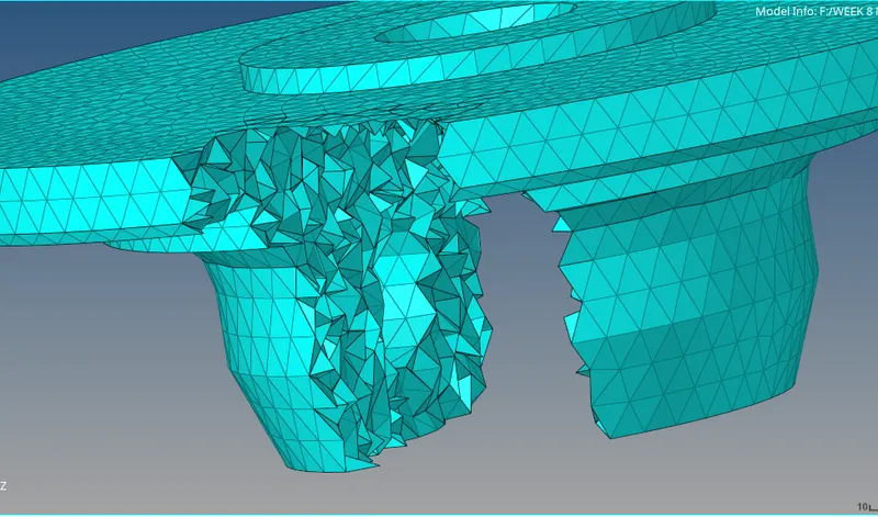
model 2
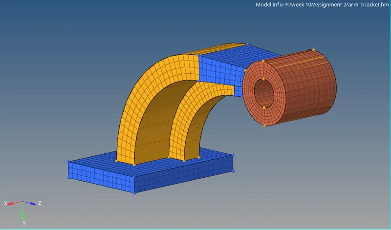
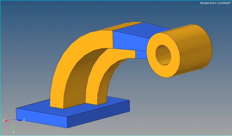 the component is divided into 4 sub part
the base
the arm curve
the arm straight
the boss
this model doesnt require any geometric cleanup
we will go for the meshing now. the first sub part we will mesh is the base
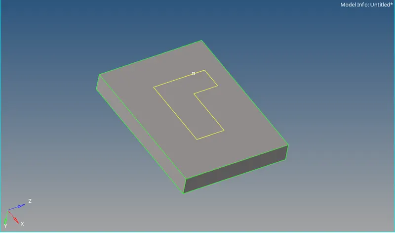
meshing the the base with element size 10

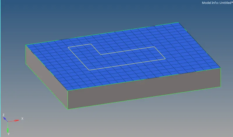
Now we will convert the 2d shell mesh into 3d solid mesh
using offset option in the 3d menu.

so we will selecting the 2d mesh we made earlier in 2d elem to offset dialog box, the no of layers of solid mesh and the total thickness over which the the 3 layer of the solid mesh should be. after the providing the required values we click offset+
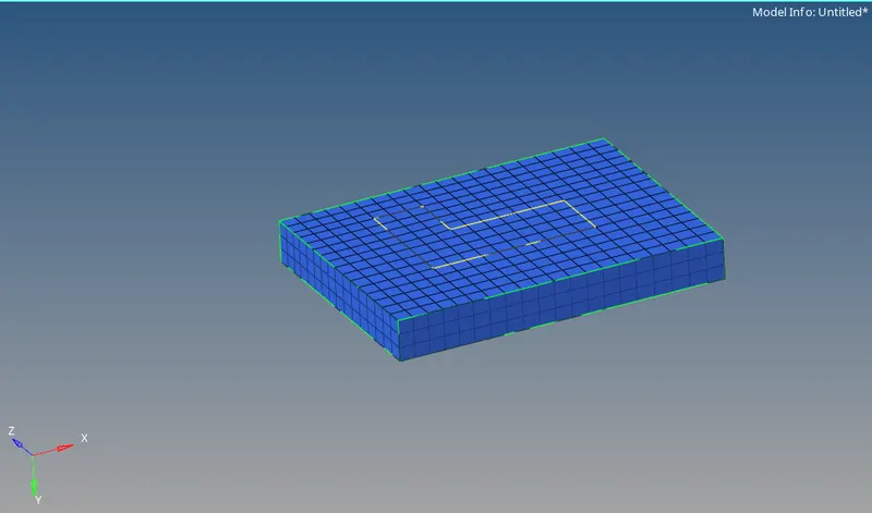
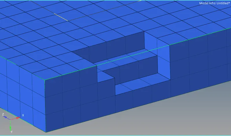
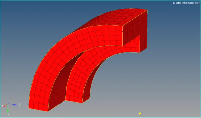
- we will mesh the arm curve
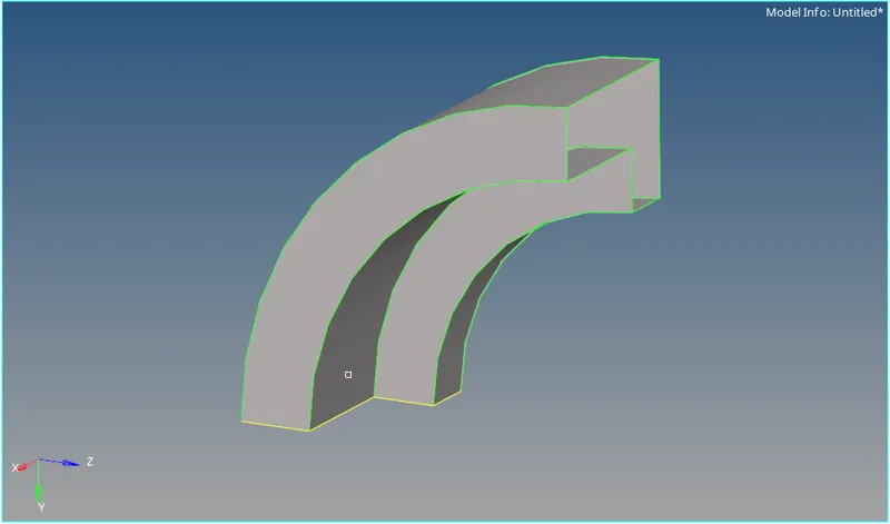
now we use the 2d shell mesh as a reference to spin the element to create the arm curve
to spin the element we require a centre, using arc centre option will select the the line option from the drop down from the dialog box
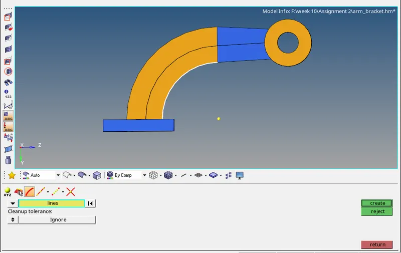
we will select the element as highlighted in the below shown image in the spin option in the 3d mesh menu
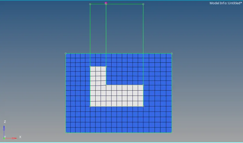


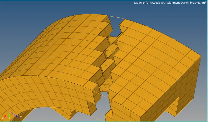
- we will mesh the arm straight
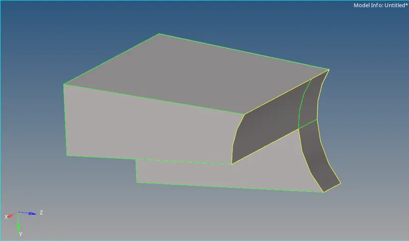
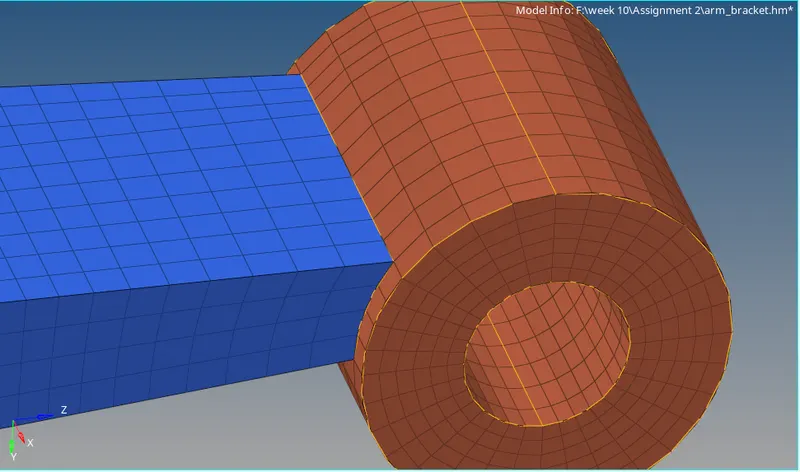
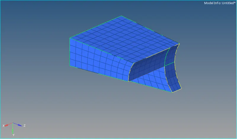
As we can see the shape of the component is consistent throught its length but one side smaller or scaled downed. so we can do the same with meshing. for this case we will use linear solid, in linear solid we fill in the space between two 2d mesh matching their spatial orientation.
to get the 2d meshing on the larger side of the component we will use the meshing of the earlier submodel. we will use find face feature in the tool menu to extract. it basically extracts corresponding 2d mesh of the already existing 3dmesh.
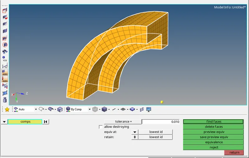
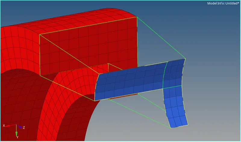
meshing the smaller surface with identical to the bigger surface.
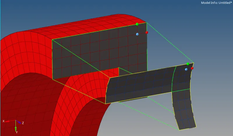

For linear mesh we have select the directin in which the mesh will move there fore the from and to dilog box does that job
for the from dialog box we are selecting the 2d element in the bigger end and providing the alignment. the aligning should be equivalent for the mesh to be proper
- BOSS
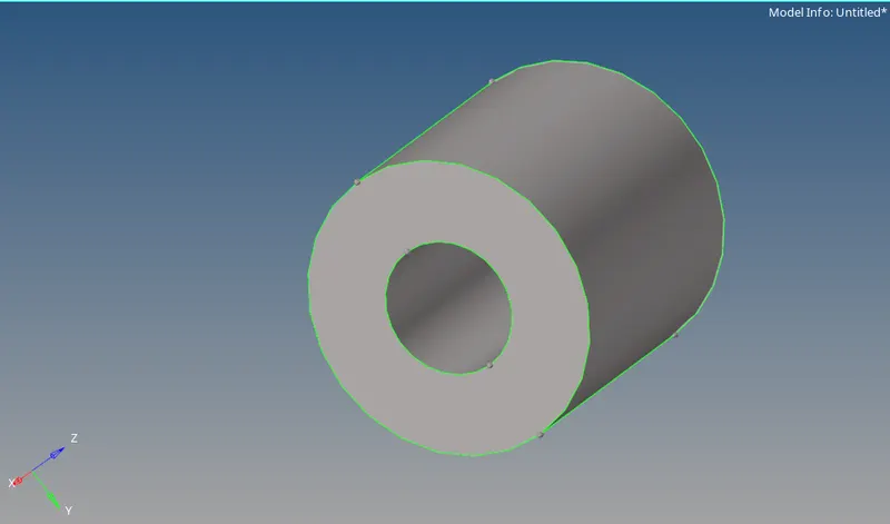
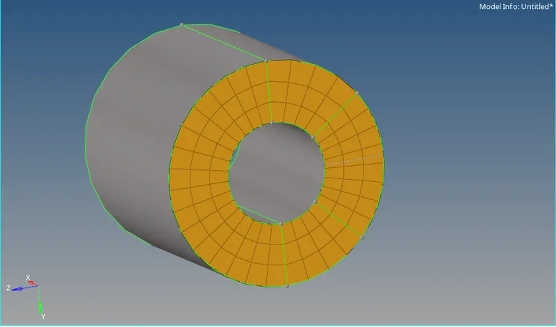
all the earlier meshing were in the same direction as the already exisiting meshes, but for the boss the new mesh will be perpendicular to the existing mesh so there are chances there might not be proper connection between the existing and new mesh. for that we have to give extra info/parameter to the software. we have to select the nodes/lines of the existing mesh for the software to make new solid elements with the existing elements