Assignment 2-RADIOSS Engine File Editing & 3D Meshing Challenge
Aim:
To study about the starter file and engine file in RADIOSS by changing the parameters for the given file. And also perform a 3D meshing on the given components of which one will have tetra mesh and the other one will have hex mesh.
Solution:
1. Check the material properties of the rail component and calculate the speed of sound in steel rail
- So to check the material properties of the material of the rail component. We have to import the component in the hypermesh.
- We have the ".rad" file. So for that, the profile should be RADIOSS.
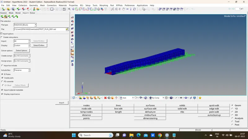
- Now we will go to the import option. There we are going to select the 0000.rad file and import it.
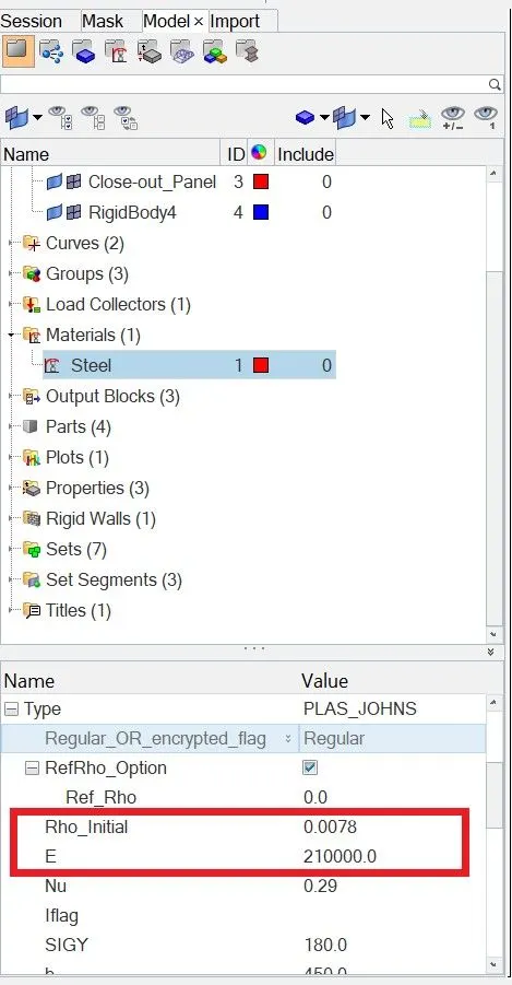
- Now we will go to material property and check the values. we can see the density and Young's Modulus of steel under Material property in Model browser window
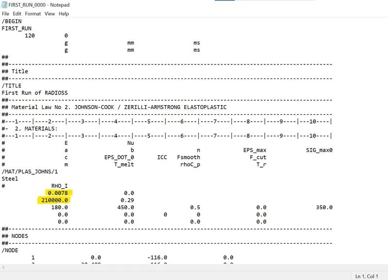
we can also open "FIRST_RUN_0000.rad " starter file in notepad and find the Material properties, as highlighted in the image below
- Speed of sound in the material (c) = c=Eρ">c=√E/ρ
- where E = Young's modulus
- ρ">ρ = density
- So speed of sound (c) = 2100000.0078">√21000/0.0078= 5188.745 m/s
2. The length of the rail is about 1000 mm calculate the time takes for a shock wave to travel from one end of the rail to the other.
- Shock wave travels at the speed of sound. So
- shock wave speed = speed of sound = 5188.745 m/s
- time (t) = Distance(D)Speed of shock wave">Distance(D)/Speed of shock wave
- time takes for a shock wave to travel from one end of the rail to the other = 10005188.745=0.1927">1000/5188.745=0.1927ms
3.Time for sound to travel length of rail= 0.1927 ms.
4. Edit the engine file so that the stress wave can be monitored, moving from one end of the rail to the other during an impact -this will require a termination time equal to the time it takes for the sound to travel the length of the rail(set on/RUN card)
- We have to give the end time to be 0.1927 ms. There are two methods to do it.
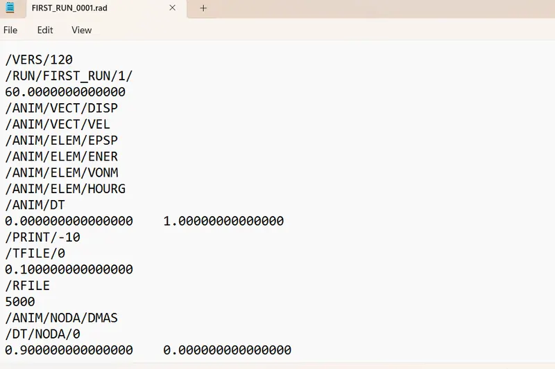
(i). First is just open the "0001.rad" engine file in Notepad and edit the end time value in the file.
Figure below shows engine file before editing the values
- Engine File after editing the required values we calculated
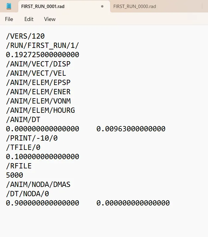
5. Set the frequency of animation output to a time that will give 20 animation steps(/ANIM/DT)
frequency = time/ no. of revolution
=0.1927/20 =0.009636.
3D Meshing
Methods to generate Tetra Meshing:
There are three methods to generate Tetra Meshing as stated below:
-
Conversion of 2D tria to Tetrahedral Elements, by using Tetra Mesh panel.
-
Using the Quick Tetra Mesh, from the Utility panel.
-
Using the Volume Tetra Mesh panel.
1 ) Conversion of 2D Tria Elements into Tetrahedral Elements, by using Tetra Mesh panel
Steps to be followed to generate Tetra Mesh:
-
Import the Model into HyperMesh and clean the geometry.
-
Delete the solid from the model, by selecting the Delete→ Solid→ Delete entity.
-
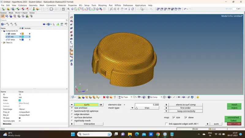
Now perform the 2D meshing on the model, by selecting the Mesh type as “Trias”.
below figure shows deploying 2D mesh on the Housing model.
4. After completing the 2D meshing, the model should be cleared with the Minimum and Maximum Elemental error
5. Now the model is ready to perform the Tetra Meshing. Select the 3D→ tetramesh option.
6. In the tetra mesh panel, select the elements under the “Fixed trias/quads to tetra mesh” option
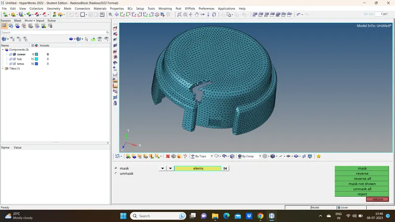
7. After selecting the elements, click on the “Mesh” button
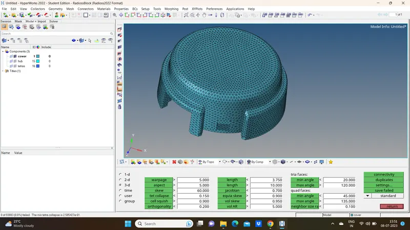
Tet Collapse
Tet collapse is one of the quality parameters, which will be checked while generating Tetrahedral elements. It can be calculated by measuring the distance of a node from the opposite face, then each of the four values will be divided by the Square root of the opposite face’s area. The minimum of four resulting values is then normalized by dividing it by 1.24.
Generally tet collapse can be calculated by the formula = Min of (h/√A) ÷ 1.24
Hexa Meshing
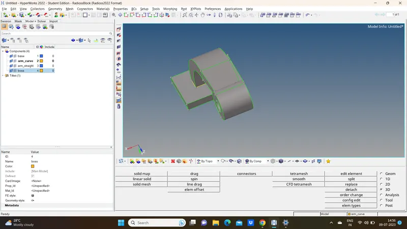
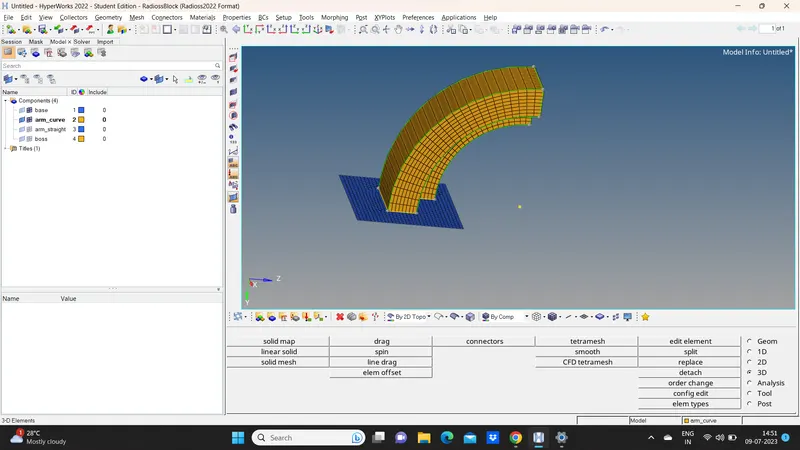
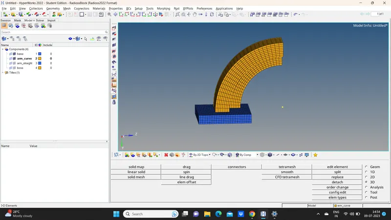
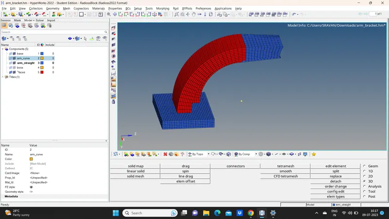
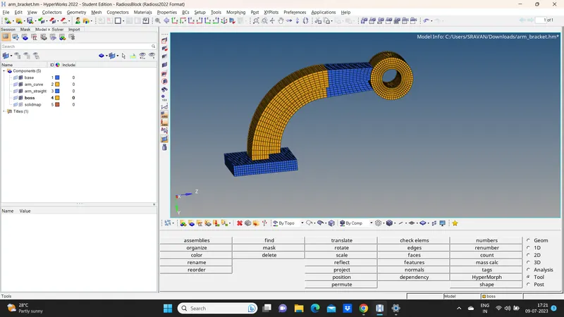
MESHING OF ARM BRACKET USING BRICK ELEMENTS
OBJECTIVE
- To import the arm bracket model.
- To clear the geometrical error, if any present.
- To mesh the bracket using brick/hex elements