Assignment 2-RADIOSS Engine File Editing & 3D Meshing Challenge
1. Calculation of the speed of sound in the steel rail.
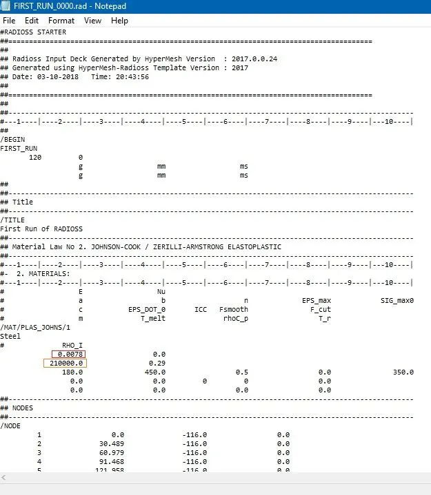
Here Rho = 0.0078 is the initial density and E= 210000 is the young’s modulus
Speed of sound,

c= `square root``210000/.0078`
=`.5188×10^4` m/s = 5188.75">5188.75 m/s
2. Time taken for the shockwave to travel a distance of 1000mm (one end of the rail to the other).
Distance, d=1000">d=1000 mm
Time Taken, t=dc=10005177.75=0.192">t= `d/c`
= `1000/5188.75` = .192 ms
3. The length of the rail is the length mentioned in question 2 (i.e. 1000 mm)
Therefore, the time taken is the same - 0.192 ms.
4. 5. & 6.
Termination time is nothing but the value of time taken that we got in question 2 (0.19272464466 m/s)
For 20 animation steps, T_freq = =0.19220=0.00963">0.192/20=0.00963ms
All these values, including /print have been updated in the engine file as shown in the below before/ after screenshot:
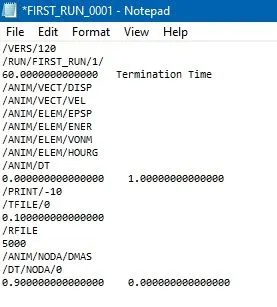
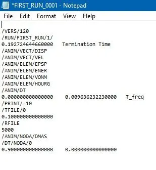
fig. before fig. after
7.
OBJECTIVE
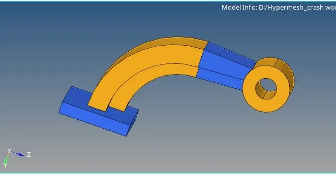
To 3D mesh the given arm bracket and housing components. The arm bracket is to be hex meshed after generating quads on its surfaces whereas the housing component is to be tetra meshed using the 2D tria mesh that is to be generated on its surfaces. They are to be meshed as per the following requirements, ensuring quality is maintained.
Target tetra size = 5 mm
Target tet collapse = 0.15
Target hex size = 10 mm
MODEL IMAGES
ARM BRACKET
PROCEDURE
ARM BRACKET
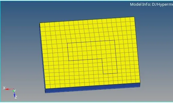
1. To start off, we can mesh the face of the base component that is attached to the arm_curve component. This is done using the automesh tool from the 2D section. With an element size of 10 mm and mesh type as quads, we can go ahead and mesh (and remesh if required). Care is taken to ensure there are no rotating quads.
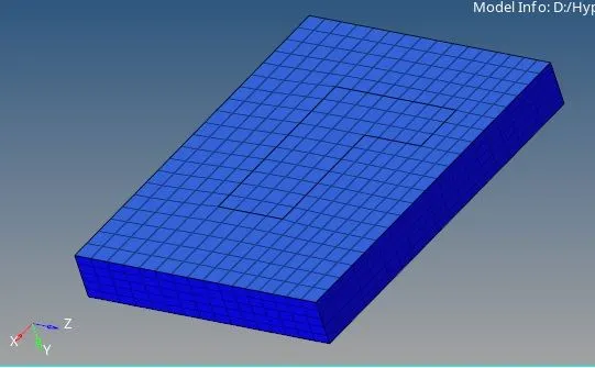
2. To create the hex elements, we can 'drag' the 2D quad elements across the thickness of the base. For this, we use the Element Offset tool from the 3D panel. With this tool, we can select the elements to be offset, the surfaces along which the elements will be offset, the thickness of the surface and the number of layers the dragged elements will be separated into. Considering the thickness of the base is 25 mm, we can separate it into 5 layers.
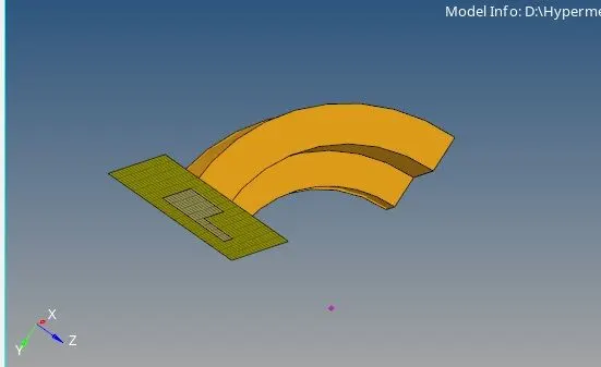
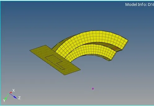
. Next, we can move on to meshing the arm curve. For this, we can make use of spin > spin elements tool from the 3D panel. Using the elements within the imprint of the arm curve on the base, we can generate a set of 3D elements with an axis of rotation (x-axis in this case) and a base point (it can be generated via geometry > nodes > arc centre and selecting the curve line of the arm). Since the arm orients itself to a final resting face that is perpendicular to the base, the angle would be 90. We can also specify the 'steps' via the 'on spin' option, for which I specified 25.
Clicking on spin+/spin- generates the set of required hex elements.
4. We can now work on the arm_straight component. The next step is to match mesh on one end of the aforementioned component with the mesh and element account of the arm_curve component. Using the automesh tool, we can mesh and remesh the face to ensure this.
The idea is to generate a 3D mesh between a pair of 2D mesh faces. But the arm curve component does not have any 2D mesh elements. For that, we shall be using the 'faces' tool from the tool panel. Through this option, we can pick the arm curve component and generate 2D faces around it (denoted in red in the upcoming screenshot).
Now that we have a pair of 2D mesh faces on either end of the arm_straight component, we can use the linear solid tool from the 3D panel to generate the 3D mesh.
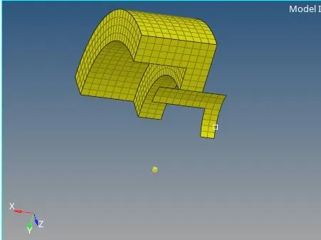
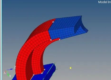
With the 2D faces generated from the arm_curve component as the 'from', we can select the mesh we created on the arm_straight component on the opposite end as the 'to'. We also need to specify nodes as guidelines to ensure the mesh matches up properly with the set on the opposite end. This is done using the alignment nodes N1, N2 and N3. In the above screenshot, the nodes of one particular element have been matched up with those of its opposite number on the other set. Finally, we can mention the density as well to generate the 3D mesh on this arm_straight component.
5. We can now move on to the final component in this model - the boss component. Before proceeding, we can delete all the 2D elements on this model up until now by going to Delete > rt. click elements > by config > select quad4 > click 'select entities' > click delete entries.
Then, we can mesh the elements on one end of the component (which we will then use as a reference to solid map the component and generate the 3D mesh). Care is taken to ensure that the number of nodes/elements along the inner circumference is the same as that on the outer circumference of the mesh.
Now, with the solid map tool (from the 3D panel), we can extract the 3D mesh using the 2D mesh, the nodes on the arm_straight component and the curved surfaces of the boss component as reference. We can make extra cut lines (using split surf-node/line tool in quick edit panel) to ensure proper mesh flow. With the elements in the above screenshot as the 'elements to drag', we can then select the opposite surface as the destination geometry. The 'along geometry' option with 'mixed' selected allows us to use multiple references, of which we shall be making use of the surfaces, node path and lines options. Every node, line and surface running between the source and destination is selected to generate the following 3D mesh.
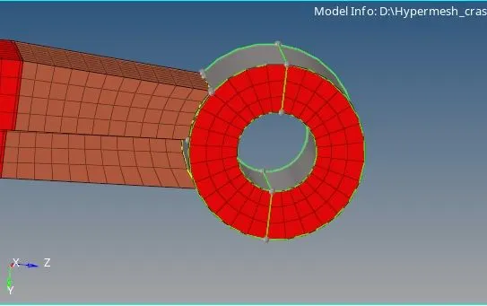
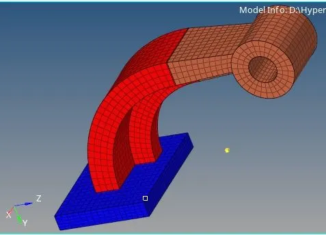
We can now delete the 2D source mesh through the process discussed before.
If a particular component's mesh isn't in the same component, we can make use of tool > organize to move them to the right component.
HOUSING
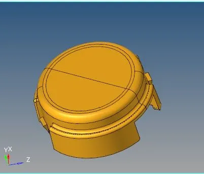
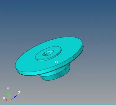
1. This model has two components - the cover and the hub. We shall look at the cover first. Isolating the component, we can check for geometry irregularities, which it did not have. Now, we can go ahead and tria mesh its surfaces using the automesh tool. With a target length of 5 mm (and no other requirements), we can mesh the surface directly as shown.
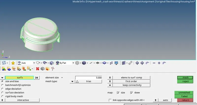
2. With the cover component as the current component, we can go to the tetra mesh tool in the 3D panel, through which we can select all the elements of the 2D tria mesh. With the tetra mesh shape being 'simple pyramid', we can go ahead and mesh it to generate the 3D tetra mesh within the cover component (Also, going to tetramesh parameters lets us specify the tet collapse limit - 0.15).
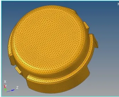
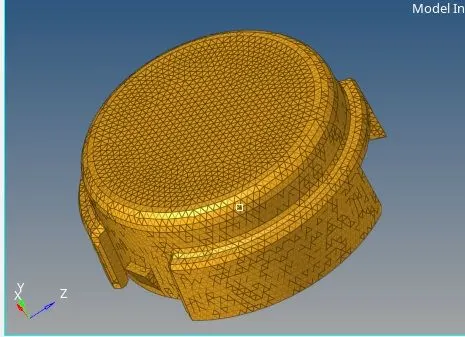
We can again delete all the 2D tria elements since we don't need them any more. This time, the config will be tria3 as shown:
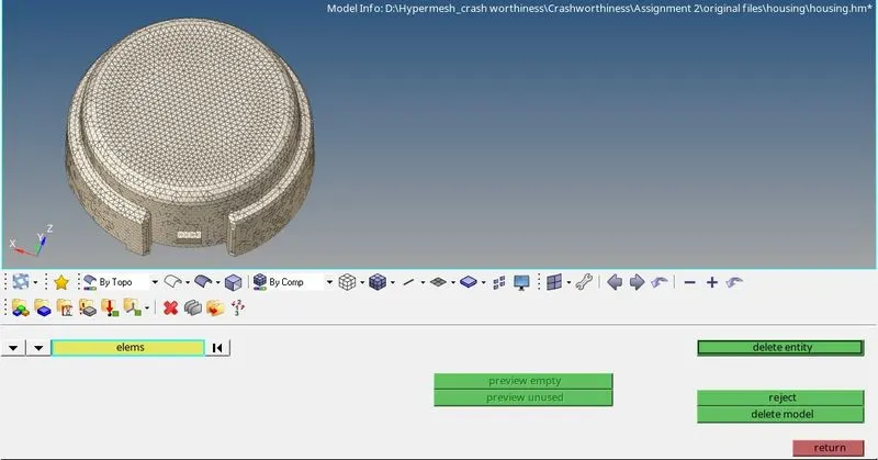
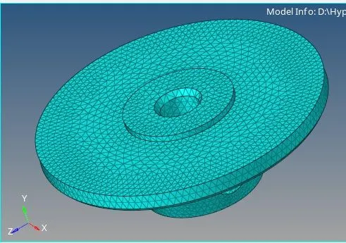
3D tetras generated:
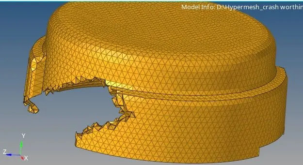
We repeat the same process on the hub component as well to generate its 3D tetra mesh.
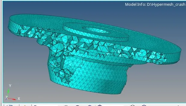
FINAL MESHED IMAGES
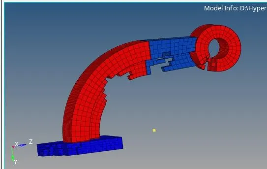
ARM BRACKET
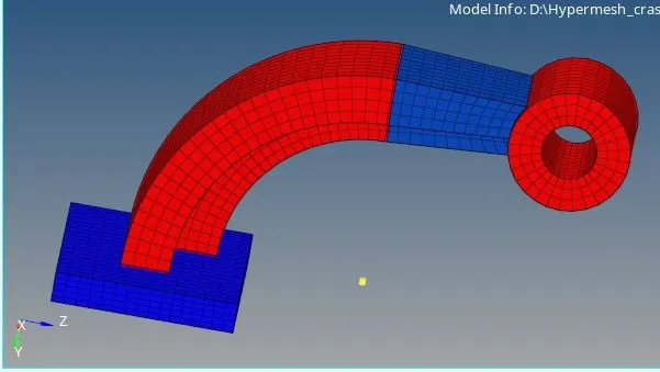
Masking of elements to showcase 3D hex elements:
HOUSING
COVER
RESULT
The given arm bracket and housing components were 3D meshed as per the given quality criteria.
Also, changes were made to the engine file as per the calculations carried out.