Assignment 2-RADIOSS Engine File Editing & 3D Meshing Challenge
RADIOSS Engine File Editing & 3D Meshing Challenge
AIM :- To perfom the RADIOSS Engine File Editing & 3D Meshing Challenge in given component.
OBJECTIVE :-
1. Check the material properties of the rail component and calculate the speed of sound in steel rail=_______
2. The length of the rail is about 1000 mm.calculate the time takes for a shock wave to travel from one end of the rail to the other.
3.Time for sound to travel length of rail=______
4.Edit the engine file so that the stress wave can be monitored, moving from one end of the rail to the other during impact -this will require a termination time equal to the time it takes for the sound to travel the length of the rail(set on/RUN card)
5.Set the frequency of animation output to a time that will give 20 animation steps(/ANIM/DT)
6.Change /print -10.
7.3d meshing tetra mesh and hex mesh
- Repeat class examples and, maintain the quality.
- Target tet size=5mm,hex size=10mm,tet collapse=0.15.
PROCUDURE :-
1. Check the material properties of the rail component and calculate the speed of sound in steel rail
Density (p) =.00078 g/mm3
Youngs modulus (E) = 210000 mpa
speed of sound (s) = √Eρ�� = 210000/0.0078 = 5188.75 mm/ms
2. The length of the rail is about 1000 mm.calculate the time takes for a shock wave to travel from one end of the rail to the other.
Length = 1000mm
speed = 5183.75 as calculated earlier
we know that s =d/t
5188.75=1000/t
t = 1000/5188.75 = 0.192 mm/ms
3.Time for sound to travel the length of rail?
the time taken for sound to travel the length of rail is 0.192 ms
4.Edit the engine file so that the stress wave can be monitored, moving from one end of the rail to the other during an impact -this will require a termination time equal to the time it takes for the sound to travel the length of the rail(set on/RUN card)
First, we import the engine file by going to file-->import---->solver deck
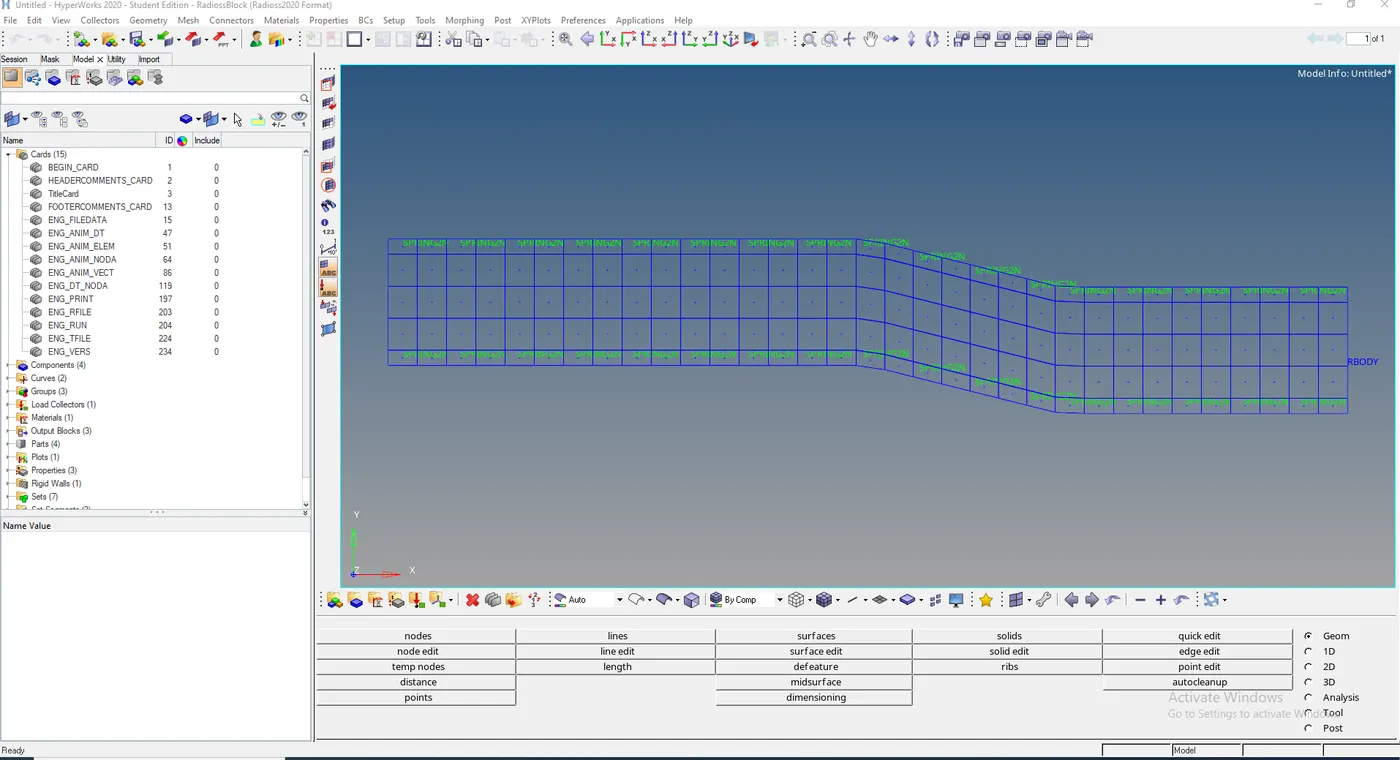
5.Set the frequency of animation output to a time that will give 20 animation steps(/ANIM/DT)
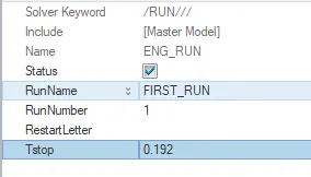
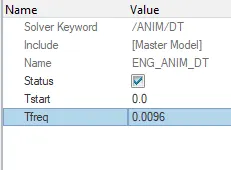
then go to the model tab and under cards we edit ENG_RUN as 0.192sec and ENG_ANIM_DT as 0.192/20 i.e 0.0096
now, we go to analysis and use the radio's function and save the file in a different folder

time to move on to the hyper view and load the file with the name FIRST_RUN.h3d and click play to observe the animation

animation :
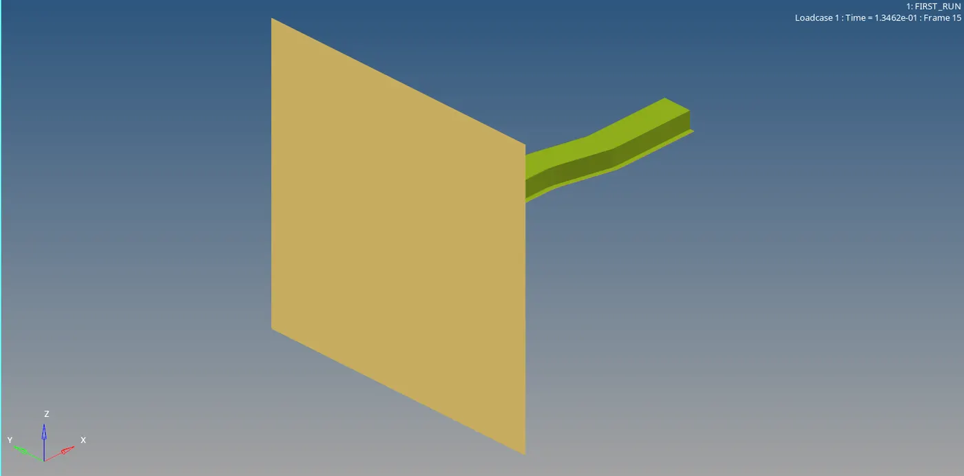
Google drive link :
https://drive.google.com/drive/folders/1UcOV5uQ5k6L8CWmjgXrmJUDH8ClBUuM_?usp=share_link
6.Change /print -10.
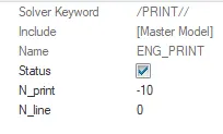
7.3d meshing tetra mesh and hex mesh
TETRA MESH :
Before meshing :
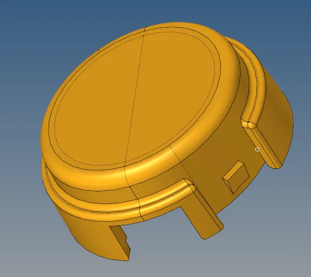
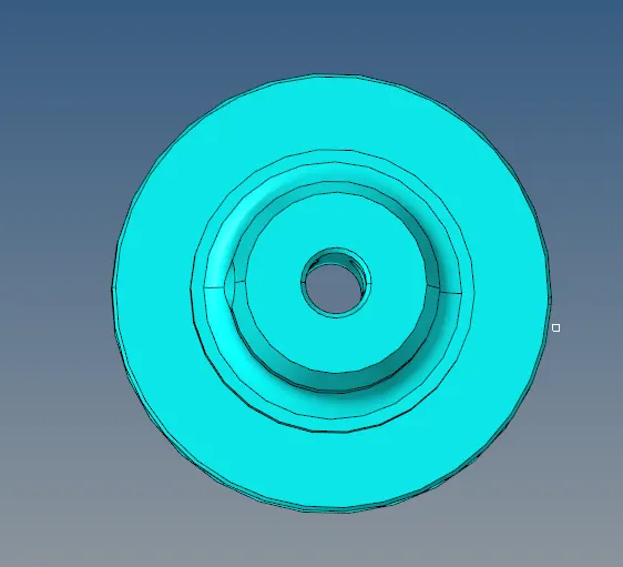
First, we do the 2-D meshing by selecting the surface to be meshed using the auto meshing function
Parameters set are :
Mesh type - trias
Element size - 5

after 2-D meshing

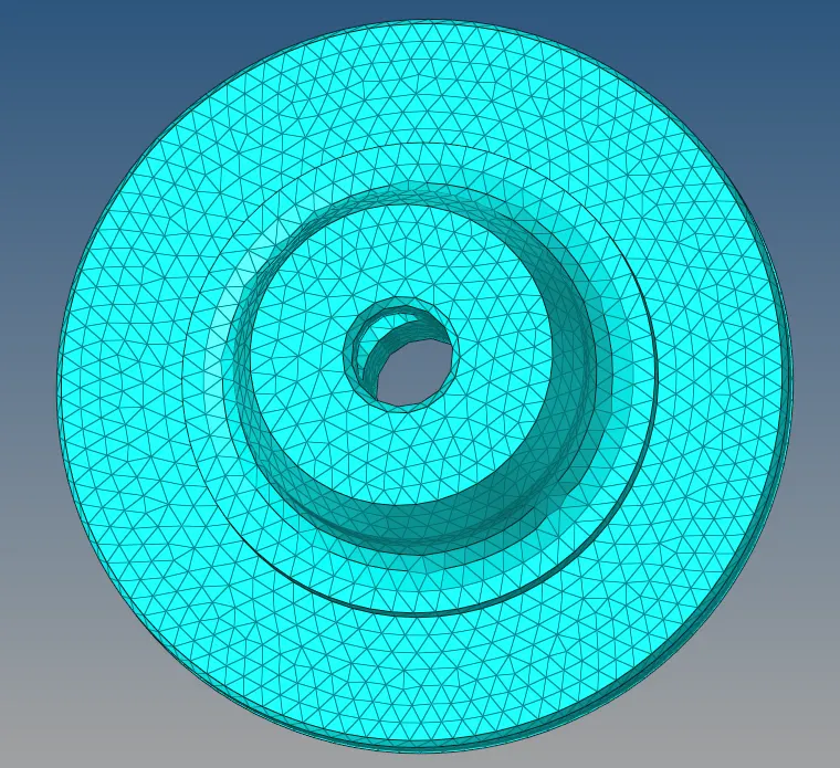
once 2-D meshing is done we move on to 3-D meshing
for 3-D meshing go to 3D and select tertamesh function
Parameters set are :
Max terta size - 5
Tet collapse - 0.15


once the 3-D meshing is done, we remove the existing 2-D mesh by using the delete function
go to delete function and select by config, choose tria3 and select entities and delete entity.

After 3-D meshing
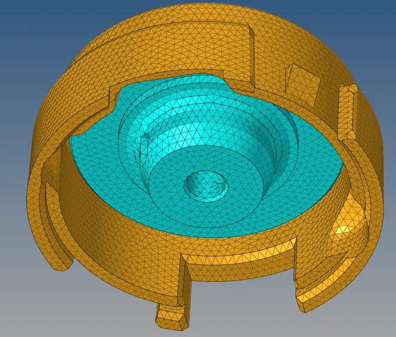
after the 3-D meshing is done we use the mask function to mask some elements and check the quality of the mesh
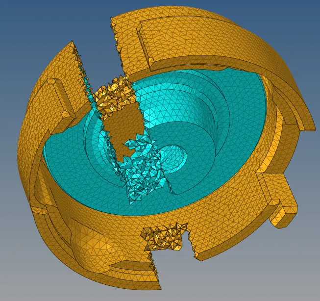
finally, we use the check element and check for tet collapse fail rate

as we can see 0 elements have failed and min tetra collapse is 0.15
the 3-D meshing is done.
HEXA MESH :
To begin with we start from the base and move up
with size as 10
we need to avoid Penta 6 elements since its unstable and we select quads only and hit mesh.

after the creation of shell mesh, we go for the element offset.select all the elements created and select the two surfaces for geometry to follow

before and after base mesh :
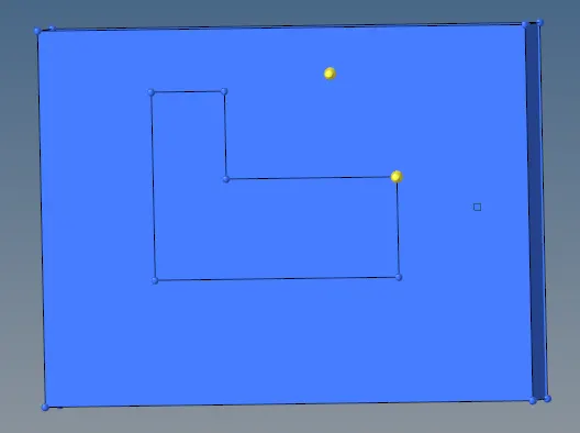
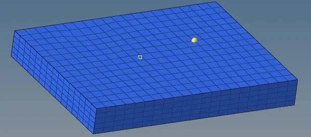
now, we move on to the arm curve
now, we make the arm curve as the current component and drag mouse click and place 3 nodes on the arm curve to find the midpoint of the arc

using the spin feature (go to 3D and select spin), select spin element and set the angle to 90 and select the centre point and hit spin-

use the delete function and delete the 2d faces
before and after the arm curve mesh :
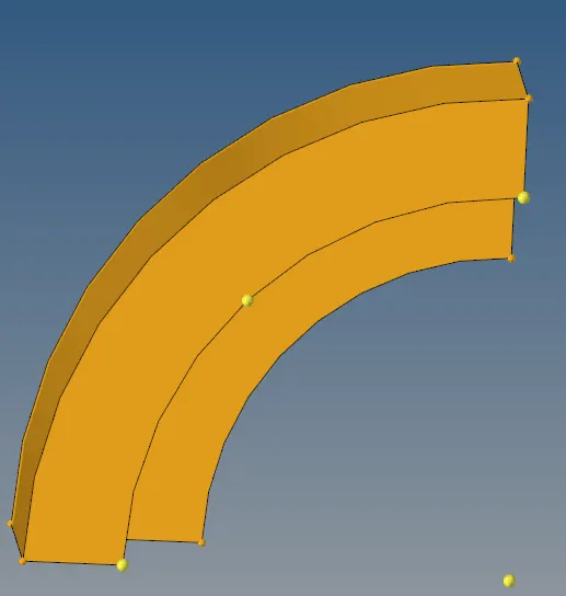
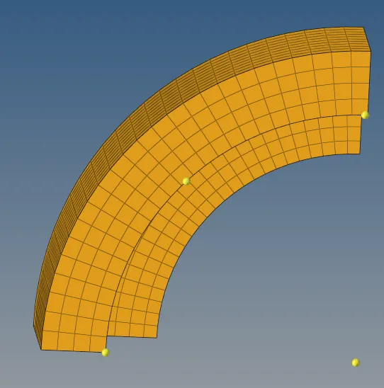
moving on to the armbar now, to project the mesh on to the armbar we need 2D elements of arm curve for that we need the faces of the arm curve
also, make sure to change the current component as arm bar
so we go to tools then faces and select the faces and click find faces

now we use linear solids function

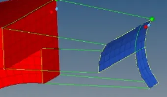 we select 3 nodes on the face of the arm curve and select exact matching nodes on the face of armbar and select reflect
to finish this use the delete function and delete the 2d faces.
Before and after armbar meshing :
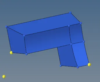
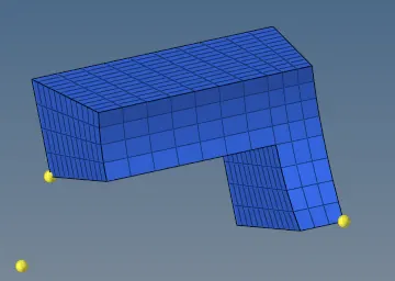
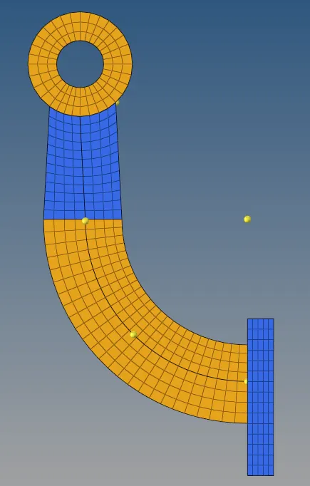
finally, we begin to mesh the boss, to start with select all the faces on the flat surface of the boss and click mesh
make the boss as
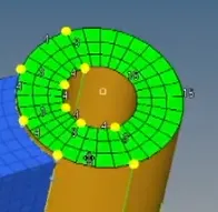
now to feed the full path of the face mesh to the other side we create a node on the other side of the face and by using the project option we project the mesh on the other side as well

to end we need to mesh the middle area of the boss, for this go to 3D and then to solid map
select the bottom surface, select the top elements to drag, a reference line and select the nodes

use the delete option select elements by config select quad4 and hit delete
this will now remove all the 2-D elements
before and after boss mesh :
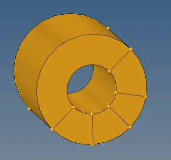
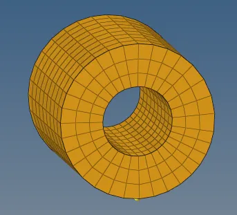
Meshing of the full model :