Assignment 2-RADIOSS Engine File Editing & 3D Meshing Challenge
Objective:
- To calculate the speed of sound through steel and the critical time step for the given length.
- To edit the Radioss engine file with the critical timestep and the frequency at which output plots are generated, for 20 steps.
- To 3D mesh the housing assembly in Hypermesh using a tetra mesh with a target element size of 5 mm and tet collapse of 0.15.
- To 3D mesh the arm-bracket assembly in Hypermesh using a hex mesh and a target element size of 10mm.
Procedure:
1. Speed of sound in steel rail :
From the Radioss starter out file FIRST_RUN_0000.rad, the initial information about the material properties and the unit system followed can be determined.
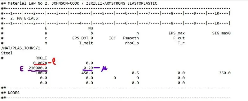
Here the material used is steel and the unit system is g-mm-ms.
The material properties in the above unit system are:
Density (Rho) = 0.0078 g/mm^3
Young's modulus (E) = 210*10^3 g/(mm.ms^2)
Poisson's ratio = 0.29.
Speed of sound can be calculated using the relation:`c`=`sqrt(E/rho)`
On substitution of the above values, we obtain C as 5188.74 `(mm)/(ms)
2)Critical Time step:
The time taken for a shock wave to travel from one end of the rail to the other is calculated as follows:
Critical Timestep `Delta` tc=lc/C
tc=`1000/5188.74`
tc=0.1927ms
3)Time for sound to travel the length of rail:
Critical Timestep `Delta` tc=lc/C
tc=`1000/5188.74`
tc=0.1927ms
4)Editing the Engine file:
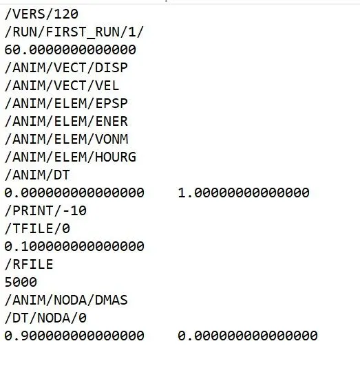
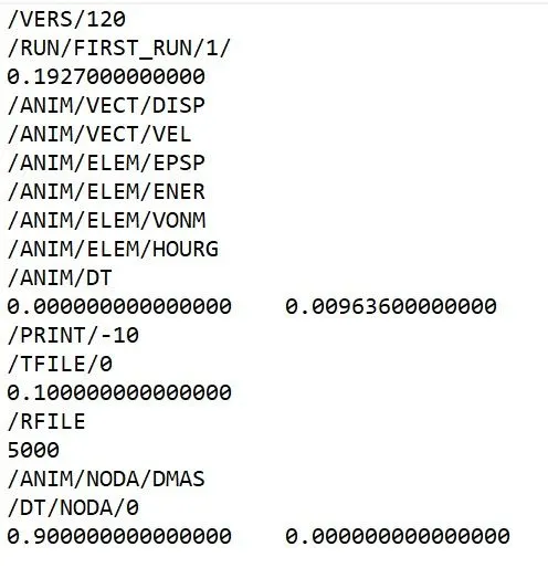
- The time interval at which plots should be written for 20 steps = 0.1927/20 = 0.009636 ms.
- The Radioss file FIRST_RUN_0001.rad contains the information about the critical time step and the time interval at which output plots are written, as shown in the figure below.
- The values of the timestep and the frequency are changed as shown below:
5)3D Mesh:
- The model is imported using the import option.
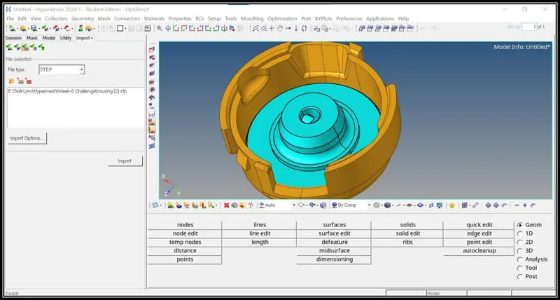
- Then in the view tab, click on browsers> hypermesh> utility.
- Then in the utility menu option click on geo/mesh option.
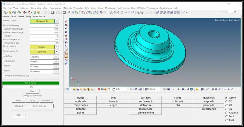
- Then in the utility dialogue box select element size and mesh type and select the component and click on the mesh option.
- The 2d mesh and 3d tetra mesh is automatically performed by the Hypermesh software.
- The tetra mesh will be saved in the separate collector automatically and it can be renamed as per our requirement.
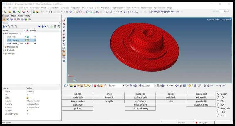
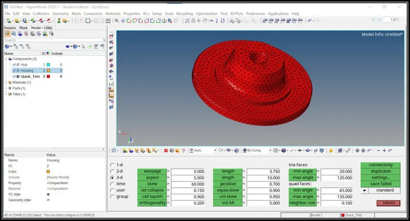
- Then the 3d tetra mesh elements are checked for tet collapse quality issue and it is rectified by using the tetra remesh option in the 3d menu option.
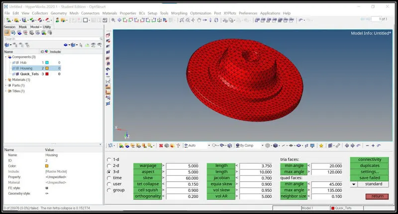
- The same procedure is followed for the housing part also to create the tetra mesh.
- Set the parameters in the utility option to create the automatic tetra mesh.
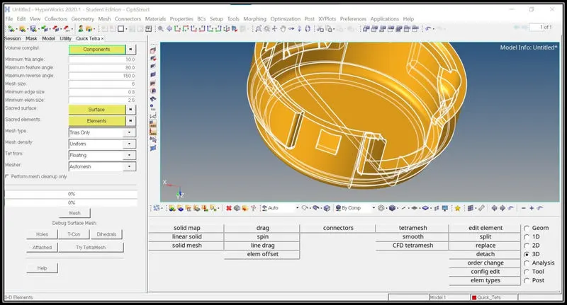
- The 3d tetra mesh elements are checked for the tet-collapse quality issue and it is cleared by tetra-remesh option.
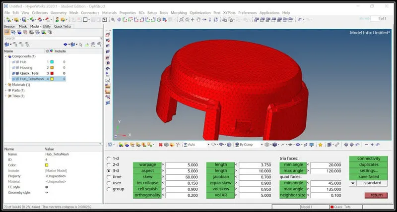
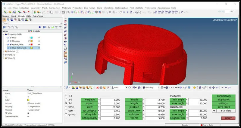
Conclusion:
- Thus 3d tetra mesh is performed automatically using the above procedure.
6)Hexa Mesh:
- The model is imported using the import option.
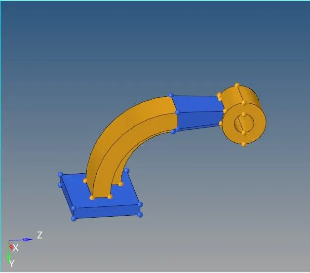
- The base plate is meshed with 2d shell elements of quads with an element size of 10 according to the given quality criteria.
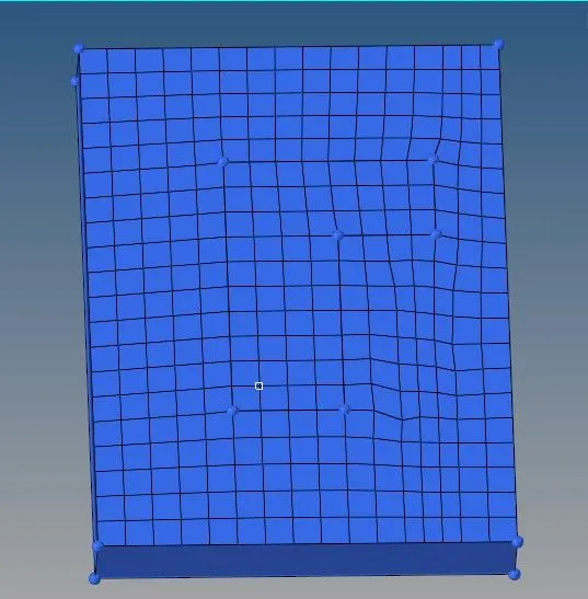
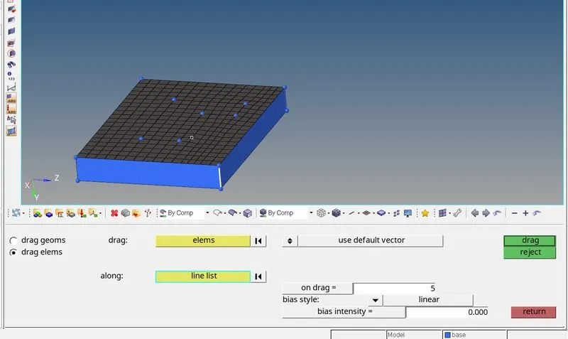
- Then using the drag option in the 3D tool page the elements are dragged along the line to form hex elements on the surface.
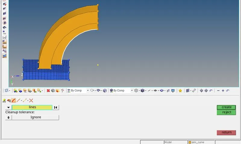
- Using the spin option in the 3D tool page the arm curve has meshed.
- Initially, create a center node using the node option geom tool page.
- Using the center node as the base point the elements are spin.
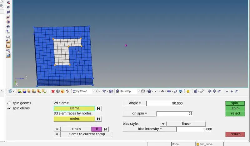
- Using the spin option in the 3D tool page, the elements on the base under the arm curve are selected and the angle is entered as 90 and on the spin option, the number of elements needed is entered and hit spin- option to spin the elements.
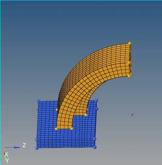
- Then using the faces option in the tool page, the 2d elements are created.
- On the other side of the arm straight 2d shell elements are created with the same number of elements as on the other side of the face.
- Then using the liner solid option in the 3D tool page, from elements, and to elements are selected and between them, hex elements will be created.
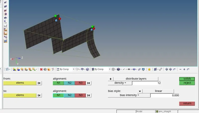
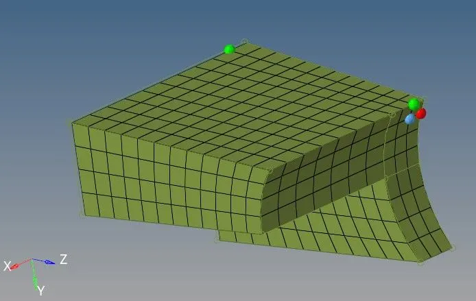
- In order to create hex elements on the boss, initially, the node is projected on the surface using the project option on the tool page.
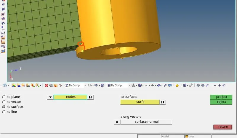
- Then on the top surface of the boss, 2D shell elements are created with the same number of elements as on the arm straight.
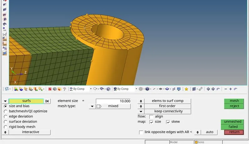
- Then using the solid map option in the 3d tool page, the destination surface, node path, elements to drag are selected and hit on the mesh option to create hex elements.
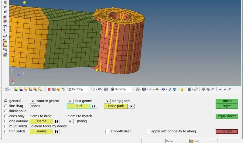
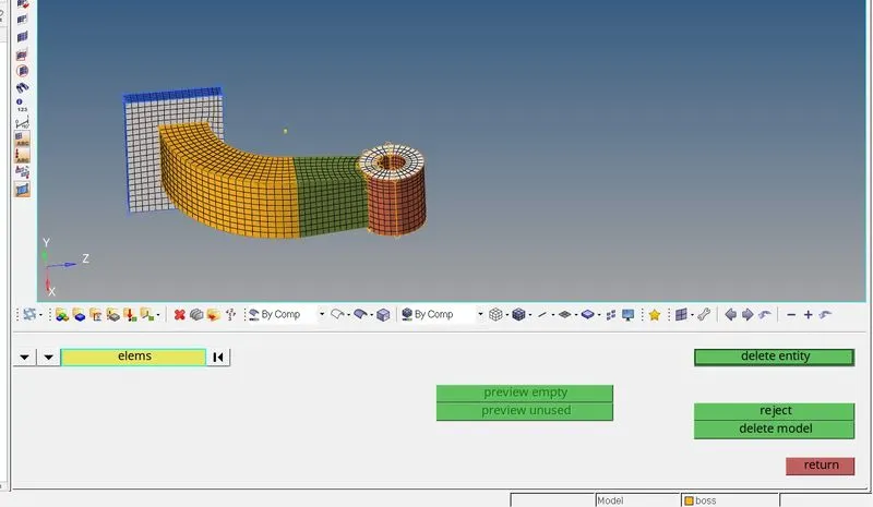
- Then the 2d elements created need to be deleted by using the delete elements by config option to ensure that only hex elements are there on the model.
Checking Free Edges:
- The Free Edges are checked using the edges option on the Tool page
- Using the Preview Equivalence option the nodes which are not connected to the adjacent node are pasted using the equivalence option.
- Again the check for the Free edges to confirm that there are no free edges inside the surface.
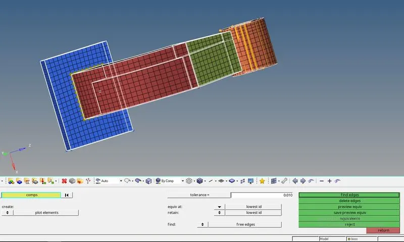
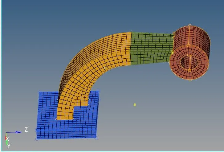
- The final image of the model will look as follows:
Learning Outcome:
- Learned to create 3-D meshing.
- Learned how to create Tetra Mesh And Hexa mesh.
- Learned about the RADIOSS files and How to run the simulation.
- Learned about how to calculate the time step, end time.