Assignment 2-RADIOSS Engine File Editing & 3D Meshing Challenge
Aim:-
- Edit the given engine file with respect to the started file in Radioss.
- Perform 3D meshing for the given housing component with prescribed quality criteria.
- Perform Hexa meshing for the given Arm Bracket.
- Deploy 1D element between the plates.
- Engine file editing
Procedure :-
1.Import 0000.rad file into Hypermesh with Radioss profile.
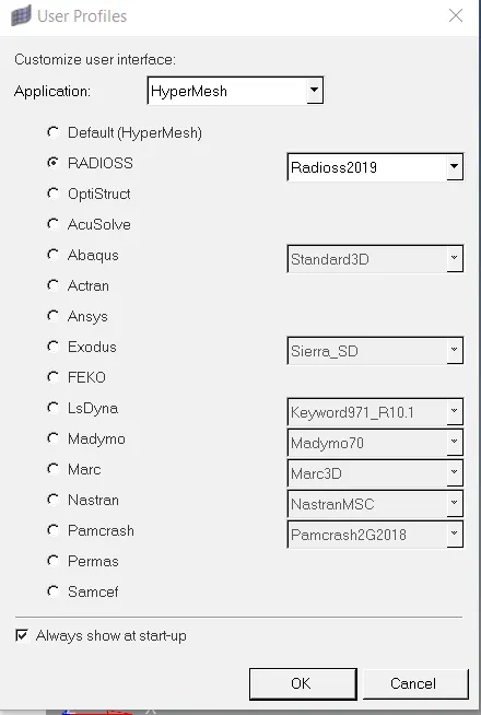
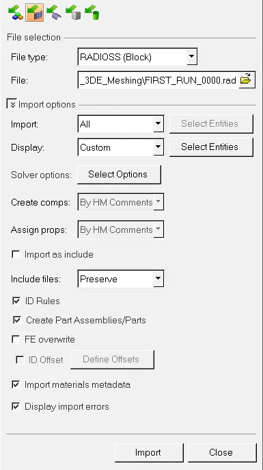
Fig 1.1 :- Hypermesh Profile Fig 1.2 :- Import Solver Deck
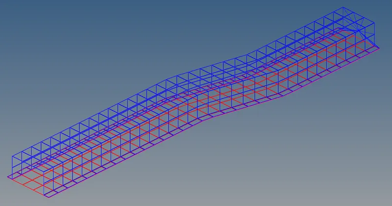
Fig 1.3 :- Imported Model
2. Check for material properties like Young's modulus & density.
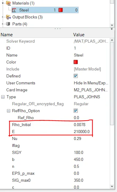
Fig 2 :- Material Properties
These values can also be view by opening the 0000.rad file in notepad.
3. Calculate the required parameters, as follows;
- Check the material properties of the rail component and calculate the speed of sound in steel rail.
Speed of sound in Steel, c = √E/ρ
Where, E = Youngs's Modulus = 210000 MPa (N/mm²)
ρ = Density = 0.0078 gm/mm3
by validating, c= √210000/0.0078
c = 5188.745 mm/ms
- The length of the rail is about 1000 mm.calculate the time takes for a shock wave to travel from one end of the rail to the other.
Time taken = Distance/Speed of sound
t = L/c
= 1000/5188.745
t = 0.1927 ms
- Time for sound to travel length of rail=0.1927 ms (mili second)
- Edit the engine file so that the stress wave can be monitored, moving from one end of the rail to the other during impact -this will require a termination time equal to the time it takes for the sound to travel the length of the rail(set on/RUN card)
- Set the frequency of animation output to a time that will give 20 animation steps(/ANIM/DT)
- Change /print -10.
Frequency = time taken/animation steps
= 0.1927/20
f = 0.009636 Hz
4. Open the 0001.rad file in notepad as shown in the snap below and edit the highlighted values with respect to the above calculations.
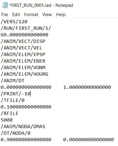
Fig 4.1 :- Engine file before editing
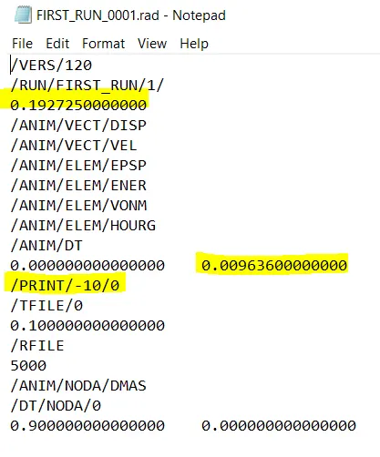
Fig 4.2 :- Engine file after editing
5. Check for the values that are reflected in the model by opening 0000.rad file.
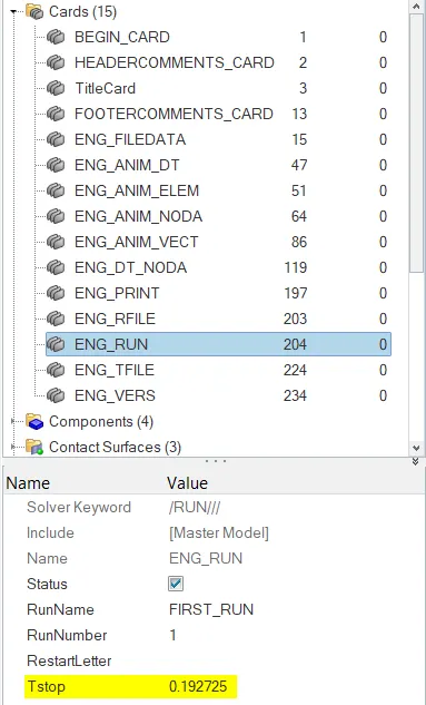
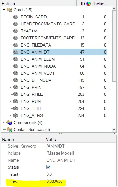
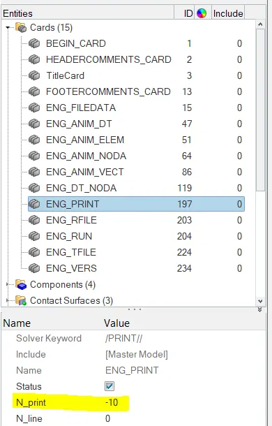
Fig 5.1 :- Time Taken Fig 5.2 :- Frequency Fig 5.3 :- Print Value
3D Meshing :-
- Import .stp file.
- Geometry Clean-up.
- 2D mesh generation.
- 3D/Tetra mesh conversion.
- Quality clearance.
Procedure :-
1. Import the given .stp file using Import->Geometry->.stp->Import.
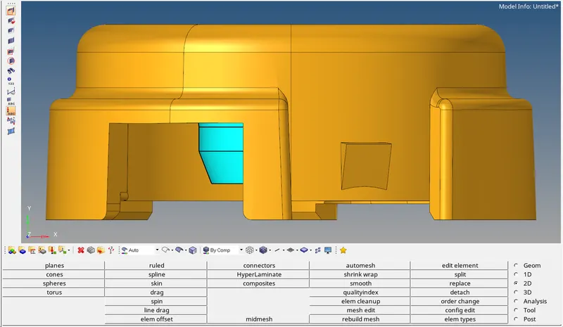
Fig 1 :- Import CAD Model
2. Delete solids in the midel using F2->solids->displayed->delete.
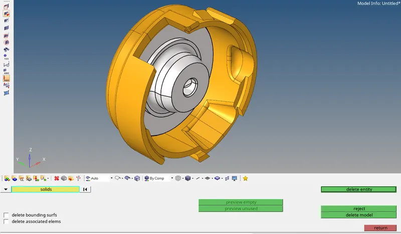
Fig 2 :- Delete Solids from the model
3. Clean-up the geometry by defeaturing and removing the unwanted lines using Geometry->Quick Edit->Toggle/Rerplace.
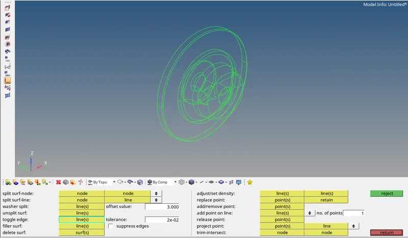
Fig 3 :- Geometry Clean-Up
4. Create 2D meshing on the clean CAD model using 2D->Automesh->Select Surface->Mesh Type=Trias->Mesh.
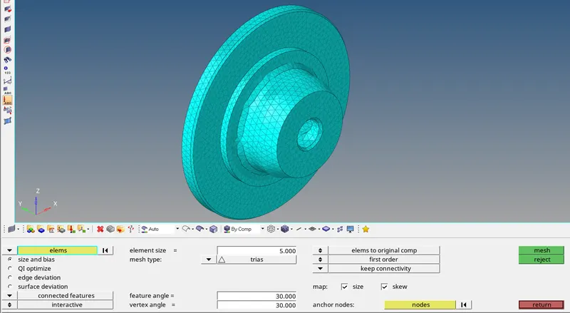
Fig 4 :- 2D Meshing on the component
5. In order to convert 2D mesh to 3D mesh use 3D->Tetramesh->Tetra mesh-> Select Elements->Mesh.
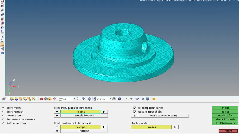
Fig 5.1 :- 3D meshing conversion
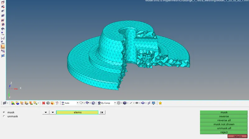
Fig 5.2 :- 3D mesh masking
6. Once the 3D meshing is completed, check for quality for Tet collapse = 0.15
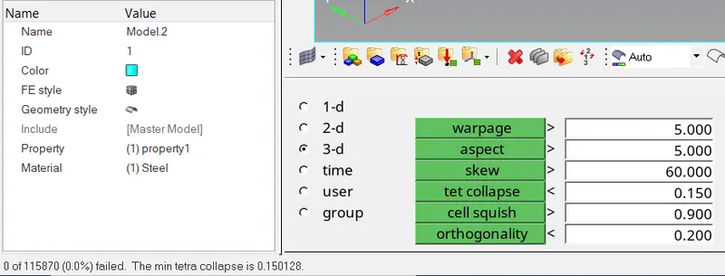
Fig 6 :- Quality Criteria
Result:-
The given housing model is meshed with 3D tetra mesh with the given quality criteria using Hypermesh.
Hexa Meshing :-
Procedure :-
1. Import the CAD model into Hypermesh. As shown in the figure, the model is divided into 4 sections namely;
- Base.
- Arm Curve.
- Arm Straight.
- Boss.
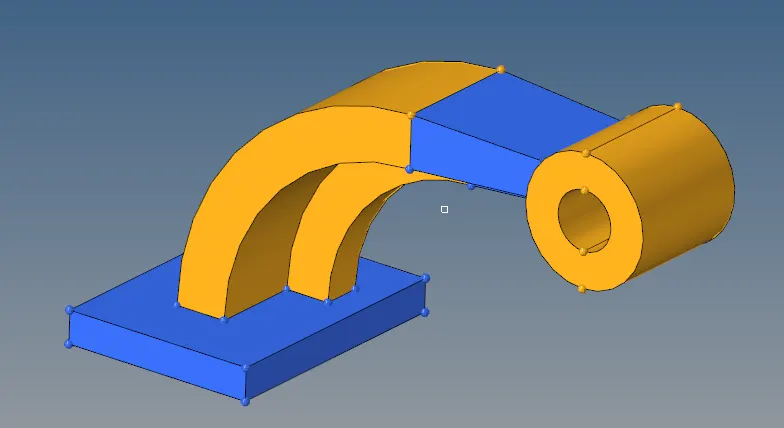
Fig 1 :- CAD Model Imported
2. Perform 2D meshing on the base part using 2D->Automesh->Select Surface->Mesh.
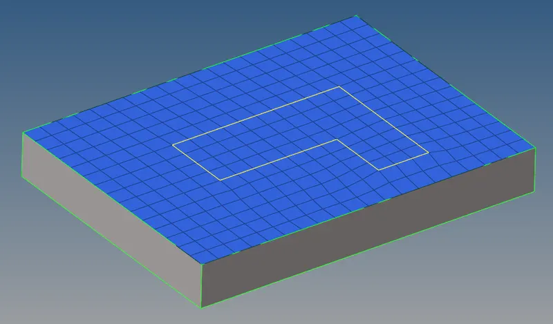
Fig 2 :- Base 2D Meshing
3. Perform Hexa meshing on the component using 3D->elem offset->solid layers->element selection->select along surface->Offset.
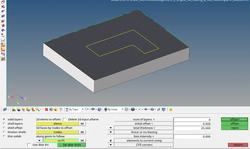
Fig 3.1 :- Hexa Meshing
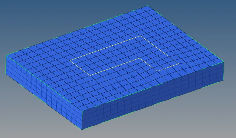
Fig 3.2 :- Hexa Meshing Completed for Base
4. Mask the Hexa8 elements and make 2D elements visible to mesh the Arm Curve.
5. Obtain the cenjter of radius of the arm curve for spin element operation using Geometry->Distance->Three Nodes->Circle center.
6. Select the elements as shown in the figure below and spin the elements along the circle center using 3D->Spin->spin elements->element selection->base point selection->Spin.
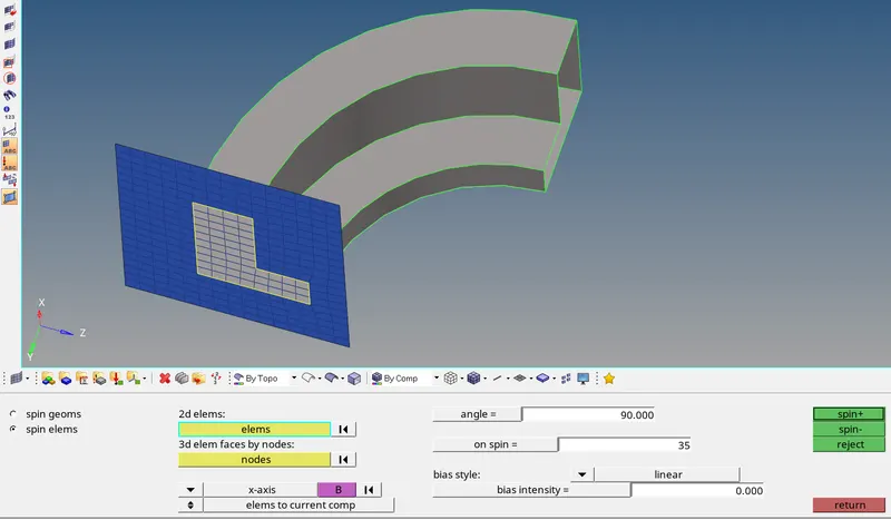
Fig 6.1 :- Hexa Meshing for Arm Curve
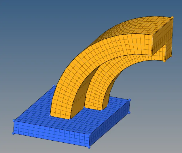
Fig 6.2 :- Hexa Meshing Completed for Arm Curve
7. Extract faces for Arm Curve and mesh the connecting surface for Arm Straight as shown below. Using solid map, move the elements from one end to another.
3D->Linear Solid->Select the elements (From & To)->Select the alignment nodes->Solids.
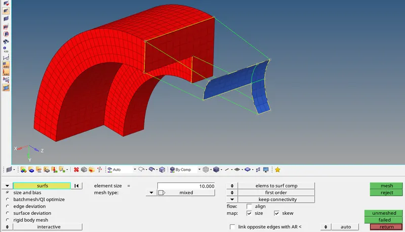
Fig 7.1 :- 2D Meshing for the connecting Surface
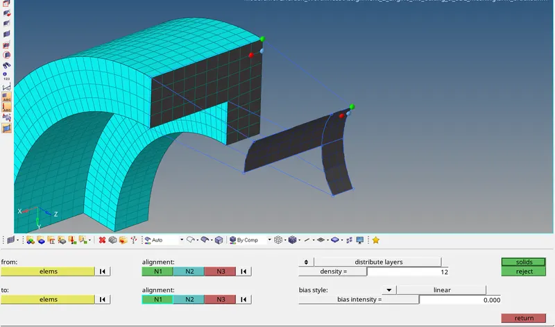
Fig 7.2 :- Linear Solid Operation
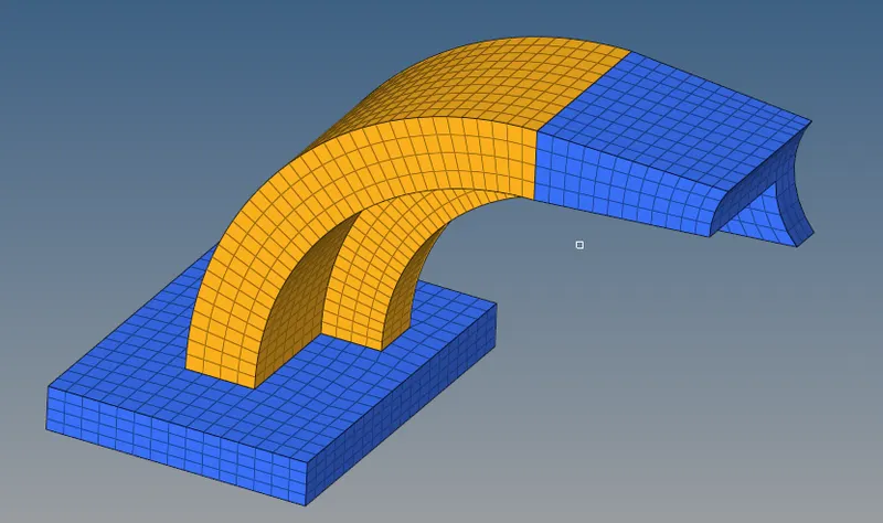
Fig 7.3 :- Hexa Meshing Completed for Arm Straight
8. In order to mesh for the Boss, project the node to side surface as shown in the figure. Perform 2D meshing on any one face to match the number of elements in the arm straight.
Using 3D->Solid map->General->Select elements to drag->node path->along geom->mesh, pewrform hexa meshing on the boss.
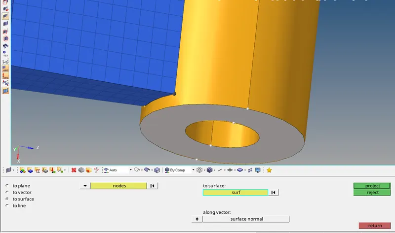
Fig 8.1 :- Projecting the Node to end surface
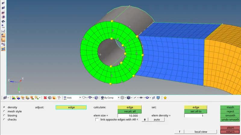
Fig 8.2 :- 2D meshing on the end surface
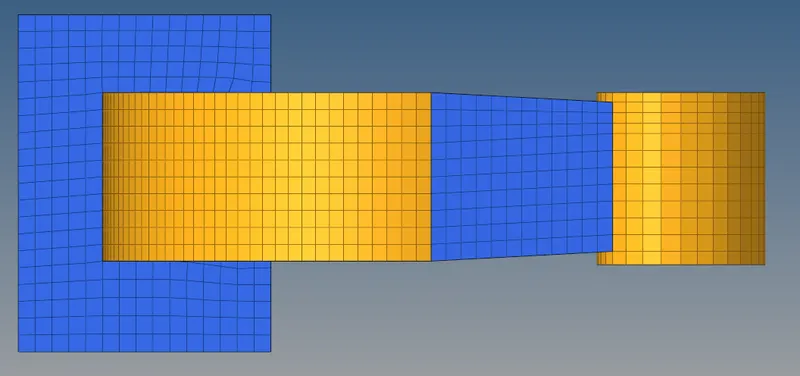
Fig 8.3 :- Hexa Meshing Completed for Boss
Final Model
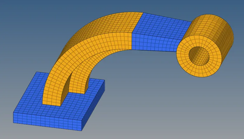
Deply 1D Element between Plates
Procedure :-
1. Import the model to Hypermesh. Mesh the surfaces using 2D->Automesh->Select surface->Mesh.
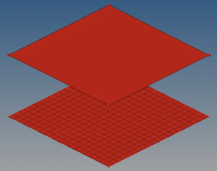
Fig 1.1 :- Import the Model to Hypermesh
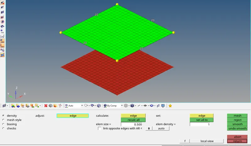
Fig 1.2 :- 2D Meshing Done
2. Deploy 1D element by 1D->Rods->Node Selection.
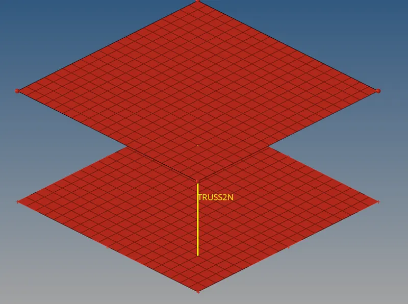
Fig 2.1 :- 1D Element connected
3. Assign beam cross section by 1D->Hyperbeams->Standard Selection->select type of beam->Create.
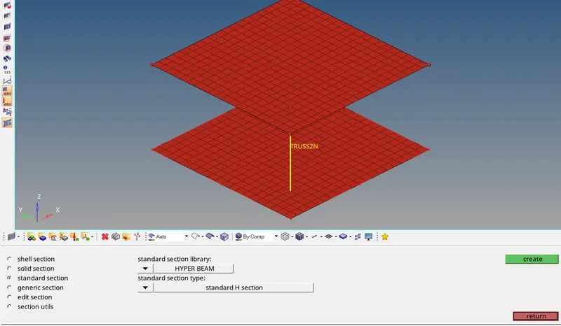
Fig 3.1 :- Hyperbeam Selection
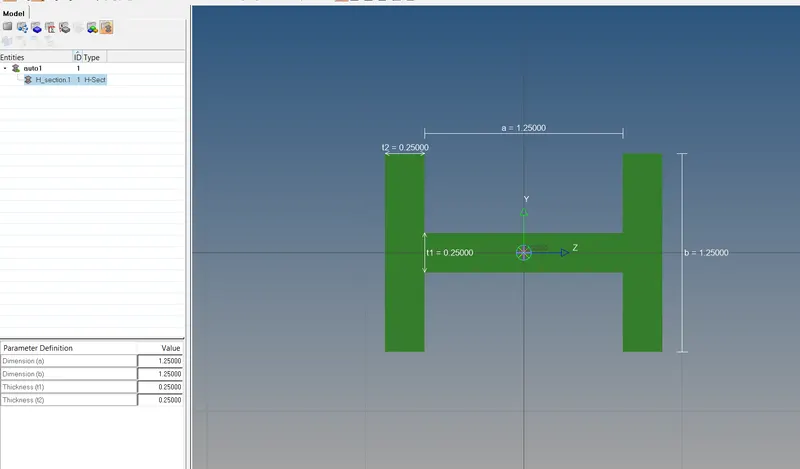
Fig 3.2 :- Hyperbeam Assigning
4. Create a new property with card image "P2_Trus". Assign the beam that was created.
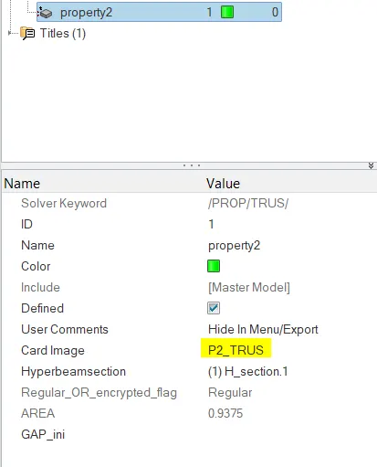
Fig 4 :- Property Assignment
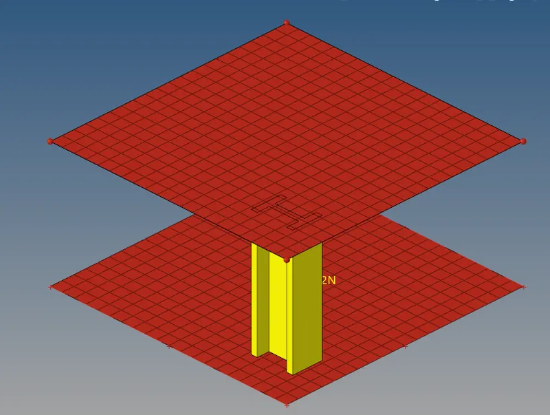
Final Model :-
Conclusion :-
The engine file is updated by calculating the required parameters using the start file. 3D tetra meshing is performed on the housing model. Hexa meshing is performed on the Arm Bracket model. 1D beam element in deployed in between the 2 plates.