Solid finite element meshing on given geometry using Hyper Mesh. Deploy Tera and Hexa element on the geometry.
Aim: - To perform 3D finite element meshing on given geometry using Hyper Mesh. Deploy Tera and Hexa element on the geometry.
Methodology
- Import model from its respective location. This model may be the step/IGS /hm file.
- Perform topology and geometry clean upon the geometry, Identify and remove all possible errors in the geometry.
- Extract Mid-surface from the actual geometry. For 3D meshing, mid surface extraction is not needed as we have to do meshing on outer surface or directly deeploy mesh.
- Deploy type of 3D mesh depending on the requirement on the geometry as per given Quality criteria.
- Check for any Quality failure and remove them.
Quality Criteria: -
1)Target length for Tetra = 5 mm
2)Hex element = 10 mm
3)Ted collapse = 0.15
There are two types of 3d elements
- Tetra Element Meshing: - The tetra elements have 4 nodes as per the below image.
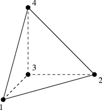
We are using tria mesh here on the outer surface of the part. So basically, on the surface, we do a normal Shell mesh but using Tria elements only. The basic idea is to create a close volume using shell mesh and then fill that volume using terta elements which are nothing but 3d / solid elements. This method is called as 2d to 3d element conversion. This is one of the three methods that we are gone see in the further segment of the report
For example, take a cube. The Square has 6 sides. So, we do shell mesh on each side/surface of the cube and then fill it's inside with tetra elements.
These tetra elements only follow the surface mesh for the first layer of mesh then it just fills the entire volume without following any pattern that’s why it’s also called Unstructured Mesh. The inside tetra element doesn’t follow the surface mesh pattern through the geometry.
- Hexa element meshing: - For its description we can say that it has 8 nodes as you can see in the image.
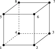
Unlike tetra elements, the Hexa elements follow the mesh pattern through its volume. You can witness the same mesh pattern on either side of the body. (Penta element serve the same role as Hexa the only difference is their shape). The Hexa mesh is called a Structured Mesh.
Only Quad elements are used in Hexa meshing.
Let's take an example of a cube again, But this time we do shell mesh on the surface by using Quad elements and follow that pattern to the other side of the face. We have to do this for each side of the cube. After shell meshing, we just have to patten that mesh so it can fill the inside empty volume.
In the Hyper mesh, a special Deck is available as shown in the bellow image which contains the options related to a different types of 3D meshing.

Fig.01
Types of Tetra Element Meshing
1) 2D to 3D element conversion: - As we discuss in the above tetra element intro. We first have to deploy a 2D element mesh on the Surface of the geometry.
In this Assignment, I get A “Housing” Assembly contains two parts, lets explore the method through the live example itself,
For the showing the first method, I had to take only the hub part.
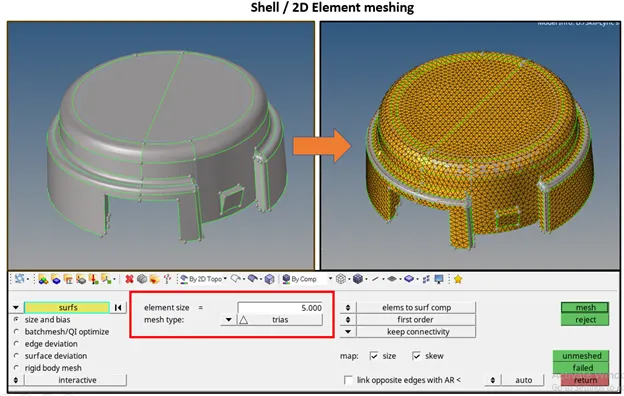
Fig.02
As you can see in the above image, I had deployed 2d mesh over the geometry using 2D Mesh Deck. I Had used the “automesh” option from the deck. The Panel you are seeing in the above image is the Subpanel from the auto mesh option which will give you the freedom to set the element target length as well as the Type of the mesh.
The Target length of 5 mm is given by the respective authorities.
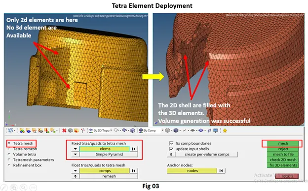
Here you can see the transformation from the 2D element to the 3D element.
2)Volume Tetra Method: - Unlike the previous method we don’t have to deploy a 2D shell element on the geometry in this method. The o7ption “Volume tetra ” will do direct volume meshing on the given component. Time taken by this method is also significantly less than the 2d-3d conversion method.
Volume Tera is the part of 3d mesh deck and you can find this option in 3d panel inside the “Tetramesh”
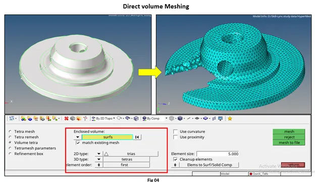
As you can see in the above image, we get the option for the selection of both types of mesh. (a mark by the red box) as well as Element size in a single panel only. After putting appropriate values and press the “Mesh” Button from the panel, Hyper mesh automatically deploy mesh on the model.
I had selected the model and feed the data given to me to generate the result we are seeing on fig 04.
3) Utility Browser Method:-
This method is easy and effective among all three methods. The main reason is under this method the Hyper mesh automatically does a defeaturing and meshing in one scope. Due to this feature, this method is praised by engineers.
To do meshing with this method first I had created a new PID and moved (tool à Organize) all the 3D elements into that newly created PID. Now, my geometry is free from the mesh and I can perform this method on the same geometry.
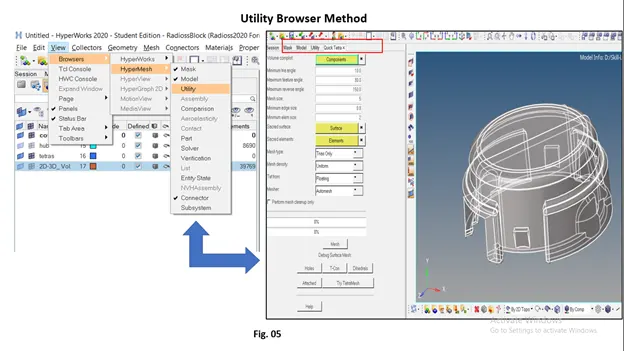
You can access the “Utility Browser” from the menu bar as suggested in the above image. The Utility Browser contains the same options like the type of mesh, target element size. We only have to select the component from the graphics window to deploy the mesh we want.
I had performed the tetra meshing using the Utility browser as the result is as follows,
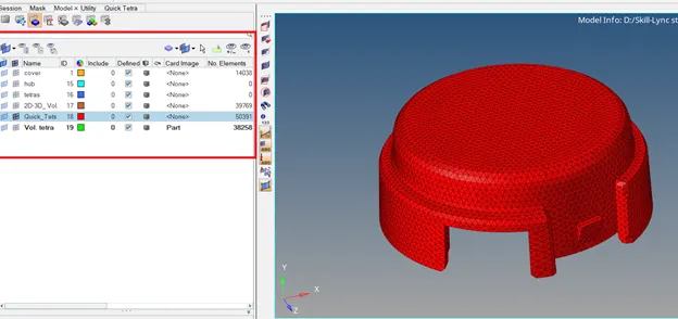
Fig 06
Hexa Element Meshing with the example
I had got another model to only showcase the Hexa element deployment. This part contains four sections with different geometry and my task was to mesh it with the Hexa elements.
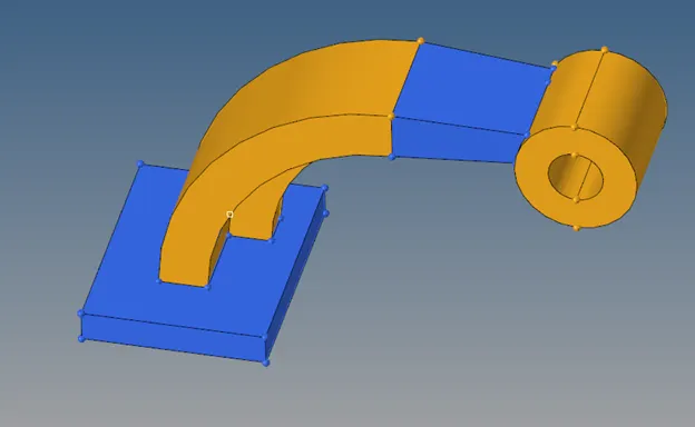
Fig07
I had used different options available in the 3D mesh deck for complete meshing of the component like element offset, solid map, linear solid, spin, etc. You can able to see these option in fig.07
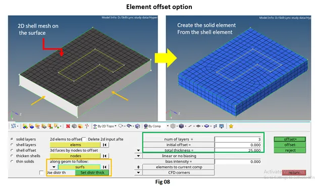
As a first step of the meshing, I had separated the bottom rectangular part from the geometry and then meshed the top surface with the 2D / shell mesh as you can see in fig.08 (left one). As you can see in the image, I had only used the quad element for the mesh.
Now, for the second step, I have to convert this shell element into 3d and transfer it along its length. For this, I had used the “Element offset” option from the 3D deck. The bottom panel you are seeing in fig 8 is the option available in that element offset button.
I first went for the “solid layer” option, where I had selected the mesh element (2d) that I want to offset than select the surfaces along which I want to offset using the “along Geom to follow” button. Set the nos of layers and the thickness and hit the offset to get 3D mesh over the body.
As you can see in fig 07 th7e next geometry is in curve path and I want my mesh patter would follow this path. To achieve this there is an option named “Spin” is available in the 3D mesh deck.
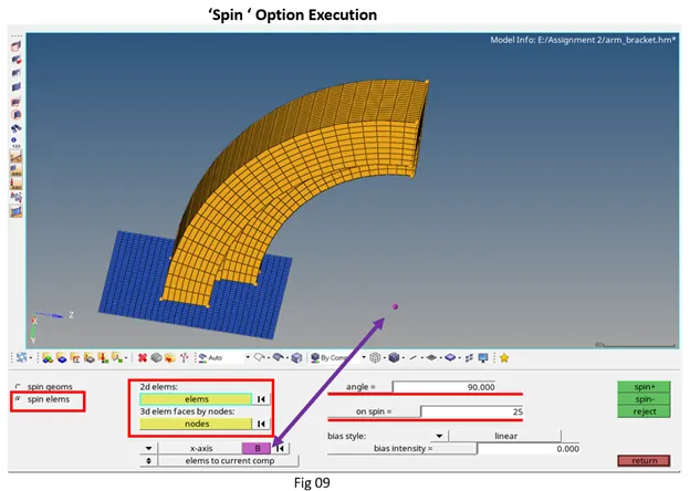
Under the spin option, I went for spin element and select the elements that I want to move along the path (NOTE: they are the 2D elements). Create the center point of the curvature to define the axis. The angle should be 90 for the curve path and also defined the spin numbers.
After hitting spin +/ - I get the result as follows,
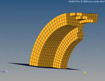
Fig 10
The 3D element generation along the curve path.
The third section of the part contains somewhat tapper geometry (Fig 07). Also the elements I get at previous operation are 3D elements, to project the 3D elements along the object length we want 2D element face. Here I used the “faces” option from the “Tool” deck to convert the 3D element outer surface into shells. So I can perform the respective operation for further Hexa meshing.
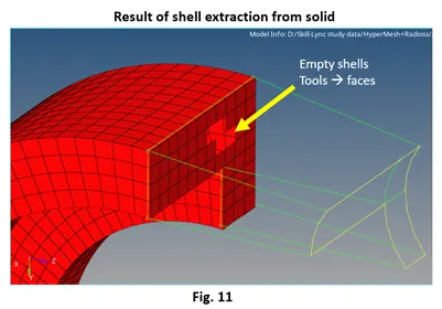
The opposite side of the shell has some geometry but its scale is different. To achieve the Hexa mesh here we have to match both of the surfaces.
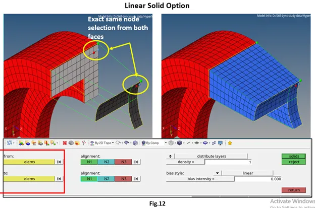
I had meshed the opposite surface with the 2D element mesh, Keeping the number of nodes on both surfaces the same as you can see in the below image.
 7
7
I had used the “Linear Solid” option from 3D mesh deck to deploy the 3D mesh on both the 2D represented surface. After clicking on the Linear solid option, you will see the panel the same as the above image, where Hyper mesh asked you about ‘from à to’ elements. here we have to select both the shell faces. In the alignment section, we have to select the exact same nodes from both of the surfaces as you can see in the above image also have to define density.
I had feed all necessary data and hit solid which gave me results as you can see in Fig.8 (Right one). And my 3D element deployment for this section is complete.
The fourth section is the cylinder one. I had used the “Solid Map” option to performed 3D meshing. The principal of mesh deployment is the same that we have to deploy 2D mesh on one face of the component and then project that mesh by converting it to 3D element up to the opposite face of the same component.
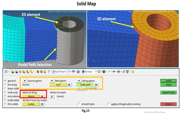
Under this option, we have to set the Source and Destination of the geometry, but here I had disabled the source geometry because I am more interested in work with the elements rather than geometry.
I had selected the elements that I want to drag on the other side of the face, select the path by node, and hit the mesh button. I got the mesh as you can see in the above image (Right).
And this is how I competed 3D Hexa meshing on the component.
Errors
During 3D element meshing the engineer more focus on the Ted collapse Quality criteria. Ted collapse is only applicable to the tetra elements.
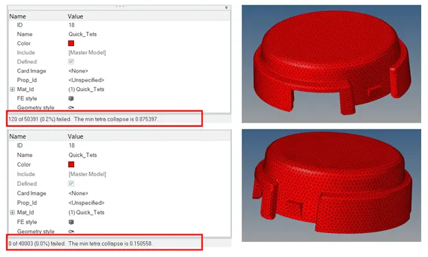
In the first window, you can see the ted collapse is 0.2% and 120 elements are failing for it. I had faced this issue during mesh deployment using the Utility browser. I solved this quality by using “Tetra remesh” under the tetra mesh panel.
Section 2
- Check the material properties of the rail component and calculate the speed of sound in steel rail=_______
So, this component with mesh and connection already deploy on it I got it in the format of “. rad”. The full name of the file is “FIRST_RUN_0000.rad”
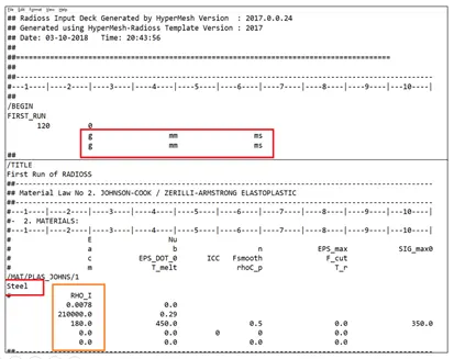
I opened this file using the import option and I get the live 3d model on my Graphics window. The highlighted part in the below image showing the property and connection data.
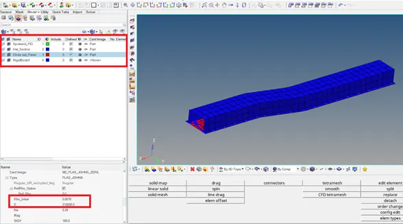
From the name I can say it is a starter input file that holds the data about boundary conditions, material, Properties, Mesh type, and connection, etc. In short, this file contains a model definition.
After reading the file by opening it in the note pad, I get the idea about the units used in this file also the material and its properties.
 77
77
The units are in gram, millimeter, and millisecond format.
The formula of speed of sound in term of density and young modulus is as follows, (we are talking about density and young’s modulus because here try to calculate the speed of sound in media which is steel so it is mandatory to follow its basic properties)
`c= sqrt (E/rho)______________________________________________(1)
Where,
c= speed of sound in material
E= Youngs modulus
`rho` = Density
From the above data, we know the E for steel is 210000 Mpa and `rho` is 0.0078 `g/(mm)^3`
after putting these values in eq. (1) we can get the speed of the sound in steel,
`c = sqrt (210000/0.0078)`
= 5188.74 m/s or mm/ms
therefore the speed of the sound in steel is 5188.74 mm/ms
2)The length of the rail is about 1000 mm.calculate the time takes for a shock wave to travel from one end of the rail to the other.
l= 1000 mm
the shock wave is nothing but the speed of the sound in that material.
The time takes by shock wave to travel from one node to the other is known as the Timestep. its denoted by `Delta t` And its formula as follows,
`Delta t = l/c`
`Delta t = 1000/5188.74`
`Delta t = 0.1927` ms
the time takes for a shock wave to travel from one end of the rail to the other is 0.1927 ms
This is nothing but a Run time for which we want to run the simulation
3.Time for sound to travel the length of rail= 0.1927 ms
4.Edit the engine file so that the stress wave can be monitored, moving from one end of the rail to the other during an impact -this will require a termination time equal to the time it takes for the sound to travel the length of the rail(set on/RUN card)
5.Set the frequency of animation output to a time that will give 20 animation steps(/ANIM/DT)
6.Change /print -10.
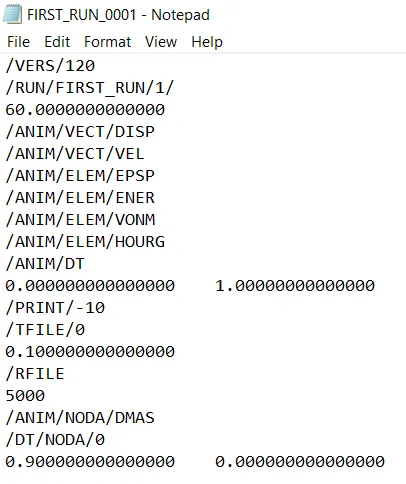
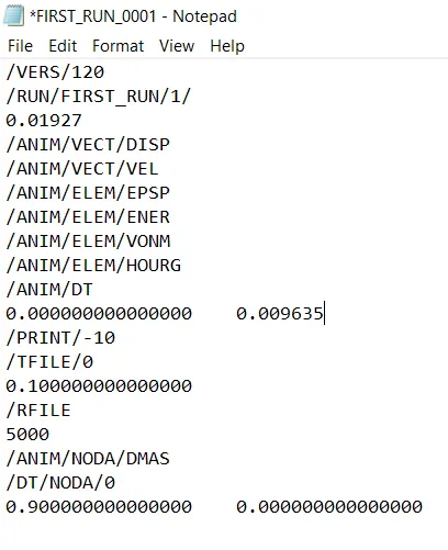
Before Changes After changes
Here I placed Run time data and Time interval to capture the animation frame. In the previous file, the run time was 60ms, and the time interval between frame capture is 1ms I had changed it to 0.01927 ms and 0.009635 ms respectively.
Conclusion
- 3D meshing/volume meshing / Solid meshing only done on the part which has a thickness of more than 6mm.
- In the Utility browser method, the defeaturing is done on the model Automatically along with the 3D mesh Deployment.
- length and Max. length criteria wouldn’t get applicable to the solid mesh as the elements are 3D elements in nature and we can’t distribute them on basis of 2d perimeters. Though we did check Tet collapse for 3d elements.
- We can save the model data and engine data in .rad format and open it by Notepad any time. We can make changes in the data file in notepad only, no need to open the entire assembly or model on Hypermesh.
- The 0000.rad file contains the basic info of the model that includes the type of mesh, Nodes information, Flow of mesh, Property details, etc.
- The 0001.rad file contains info related simulation like simulation time, time-step, force distribution, etc.