Assignment 2
Aim
To run the simulation at 1800 rpm and find out air flow rate, BMEP, BSFC and Incylinder- pressure and also run the simulation at 3600 rpm with increase of power output by 10%.
Brake Mean Effective Pressure (BMEP)
The comparative measure of power capabilities of engines which operates with same engine displacement and speed and forms a basis for the index performance.
BMEP = `(60000*BP)/ (LAN)` Pa
where
BP = Brake Power
L = Stroke length
A = Cross Sectional area of Cylinder
N = Engine rpm
Brake Specific Fuel Consumption (BSFC)
The specific fuel consumption(SFC) is defined as the total fuel consumption per h per kW developed. When BP is used to calculate SFC it is termed as Brake Specific Fuel Consumption.
BSFC = `(60 * omegaf)/(BP)`kg/bkWh
where
`omegaf` = fuel supplied kg/min
BP = Brake Power
Brake Power
The actual work output of an engine at the crankshaft is called as Brake Power.
BP = `(2*pi NT)/(60000)`kW
where
N = Engine rpm
T = Torque
Compression Ratio
The ratio of total volume of the cylinder to the clearance volume.
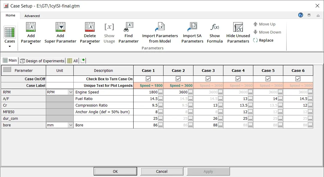
Case Setup
At 1800 rpm Case 1
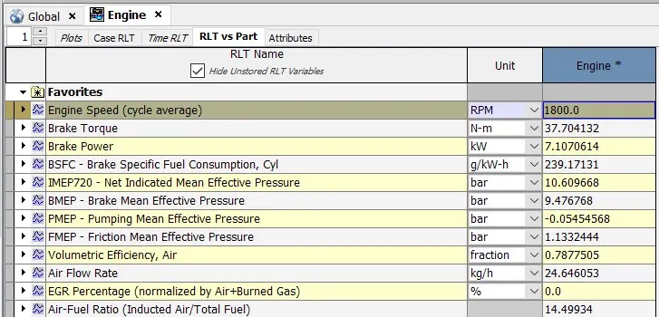
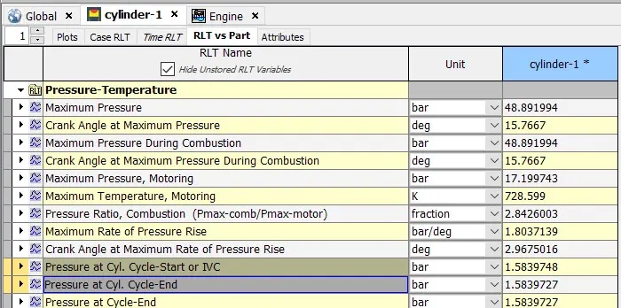
Brake Mean Effective Pressure (BMEP)= 9.476768 bar
Brake Specific Fuel Consumption (BSFC) = 239.17131 g/kW-h
Air Flow Rate = 24.646 kg/h
Incylinder Pressure = 48.8919 bar
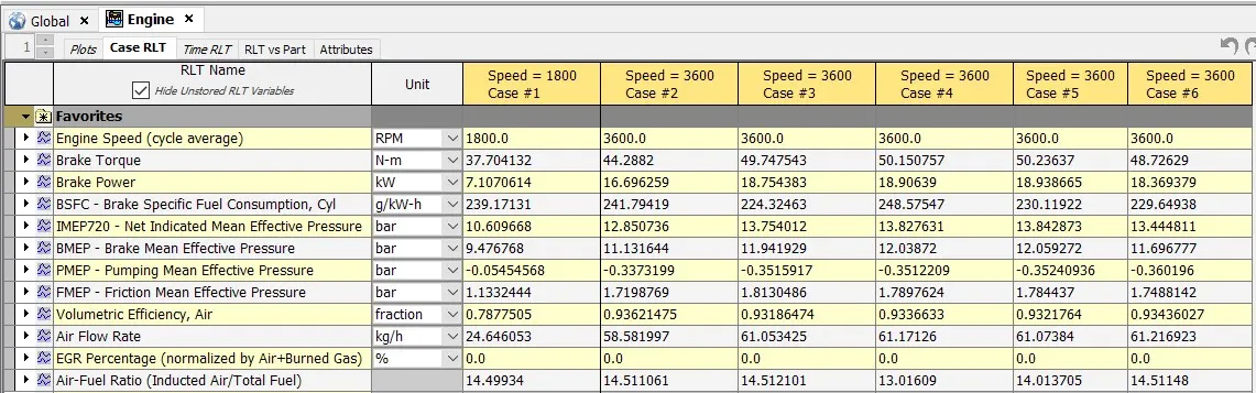
At 3600 rpm Case 2
The case setup shows that for case 1(1800 rpm) and case 2(3600 rpm) the default parameters are used for both.
- For Case 2
Brake Mean Effective Pressure (BMEP)= 11.13164 bar
Brake Specific Fuel Consumption (BSFC) = 241.79419 g/kW-h
Air Flow Rate = 58.5819 kg/h
Brake Power = 16.6962 kW
So for the cases 3 to 6 different parameters are used to increase the power output by 10% from the base case setup 2 .
- For Case 3
The paramters that are changed are
Bore = 88 mm
Air/Fuel ratio = 14.5
Compression ratio = 13
Anchor Angle = 8
Duration_combustion = 26
when these changes we can see the increase of power from 16.69 kW to 18.75 kW.
Brake Power = 18.75 kW
- For Case 4
The paramters that are changed are
Bore = 88 mm
Air/Fuel ratio = 13
Compression ratio = 13.5
Anchor Angle = 12
Duration_combustion = 25
When these changes we can see the increase of power from 16.69 kW to 18.90 kW.
Brake Power = 18.90 kW
- For Case 5
The paramters that are changed are
Bore = 88 mm
Air/Fuel ratio = 14
Compression ratio = 13.5
Anchor Angle = 12
Duration_combustion = 25
When these changes we can see the increase of power from 16.69 kW to 18.93 kW.
Brake Power = 18.93 kW
- For Case 6
The paramters that are changed are
Bore = 88 mm
Air/Fuel ratio = 14.5
Compression ratio = 12
Anchor Angle = 12
Duration_combustion = 25
For these changes we can see the increase of power from 16.69 kW to 18.36 kW.
Brake Power = 18.36 kW
Result
As we can see that when change were made we can see an increase in Brake Power(BP) and also increase in Torque.
These changes in parameters were made with not only increasing BP but with lower fuel consumption as possible therfore in order to follow this criteria changes were made to the compression ratio and to the anchor angle with maintaining an reasonable compression ratio and the Air/Fuel Ratio.
The best cases for increase in BP and Less Fuel Consumptions are Case 3 and Case 6. These cases not only increased the BP it also reduced the emission of CO and NOx from base Case 2.
A link is attached to view the performance of the varies case setups.
https://drive.google.com/file/d/1dXIvxXtc0fqozpmw3j328058r8gHMqAP/view?usp=sharing