Assignment 2
Aim:
The main aim is to perform a 3D and a Hexa mesh for the given model and to understand the basics of Radioss.
Procedure:
For Tetra Mesh:
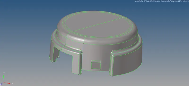
- Opening of File:
- The File opening does requires few steps to be followed which then results in the opening of the file.
- the Model is of ‘.hm’ format, therfore, go to the Files>> Click Open >> Select the File >> Click Open.
- Giving the Quality Criteria:
- Target tet size=5mm,
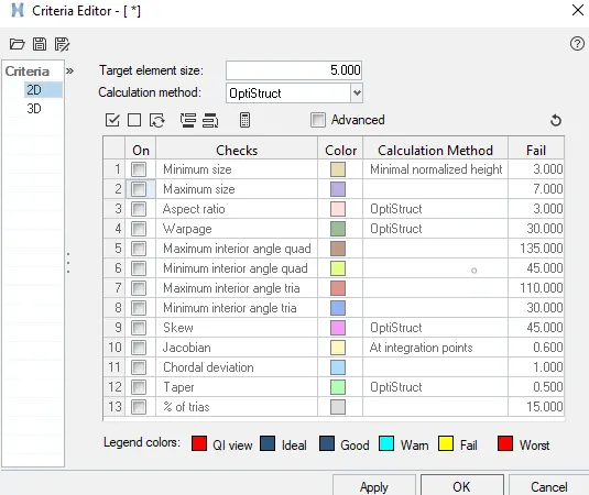
- hex size=10mm,
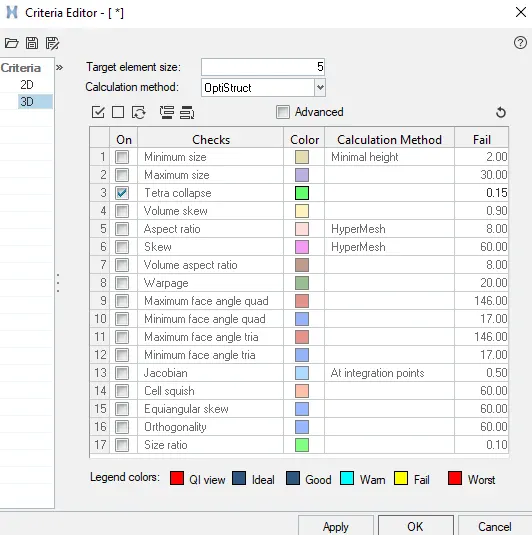
- tet collapse=0.15.
- Performing a Volume mesh:
- The Volumetric Mesh is done for the component that follows three different methods in which the volume can be extracted. The methods are as follows.
- For Tetra Mesh, 2D surface mesh followed by the 3D Volume Mesh:
- Initially, after the file is opened. Check for the Geometry.
- If it is a solid delete it to create a surface.
- Click F2>> select Solids >> Select the Model >> Click on Delete Entities/ middle-click on the mouse.
- The surface of the component appears. The Quality criteria of the model should be given. Both the 2D and 3D should be given.
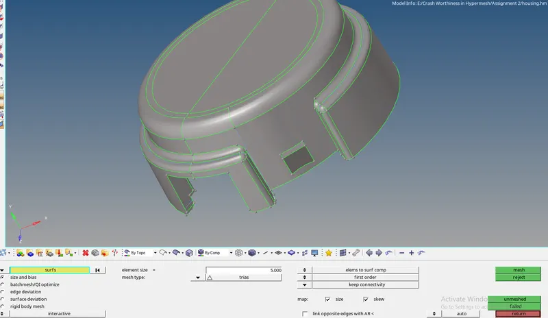
- The component needs to be meshed.
- For mesh, Click on 2D tab >> automesh >> select surfs option >> give element size as 5 (given Quality Criteria) >> Select Mesh type as Trias >> Click Mesh.
- Clean the errors faced during the mesh. Most of the errors will minimum and Maximum length errors.
- Once the mesh is done, 3D mesh needs to be done to get the volume of the given component.
- Before mesh, the meshing parameters need to be completed so that the mesh is completed within those parameters.
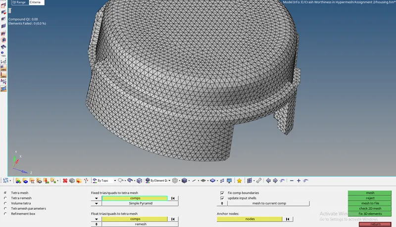
- Go to the 3Dpanel >> Tetra Mesh Tab >> Select tetra mesh parameters >> check the box of Maximum Tetra size, fill voids, fix mid nodes, smoothing boxes and, select the Minimum Tetra Size >> select element quality target as 15.
- Go to the 3Dpanel >> Tetra mesh tab >> select the component to be meshed >> Select fix comp boundaries, update input shells >> Click Mesh.
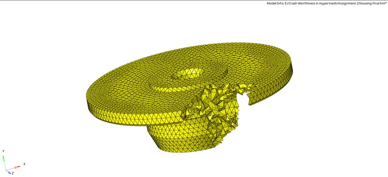
- The Solid Mesh is Created. The Mask Option is used to check if the solid is created or not. (Mask Tool hides the elements selected.)

- Checking for Tet Collapse:
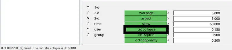
- Go to the Tools Menu, Click Edit Elements >> Go to the 3D sub-panel >> Click on Tet Collapse.
- Check that Tet collapse is zero.
For Hexa Mesh:
Hexa mesh is done on block elements. For the Hexa mesh to be created only quad elements need to be created.
- Creating an Element offset :
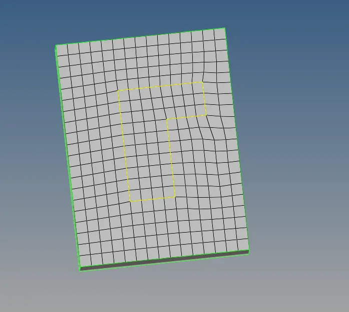
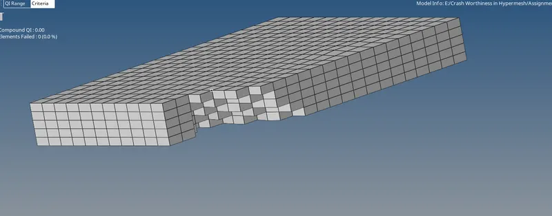
- Import the model into the HyperWorks and then create the 2D shell mesh using the quad element only on the base of the component.
- In 2D Tab>> Click on automesh panel >> Select the element size as 10 >> Select the Element Type as Quads >> Click Mesh.
- To convert the quad into Hexa, we use Element offset.
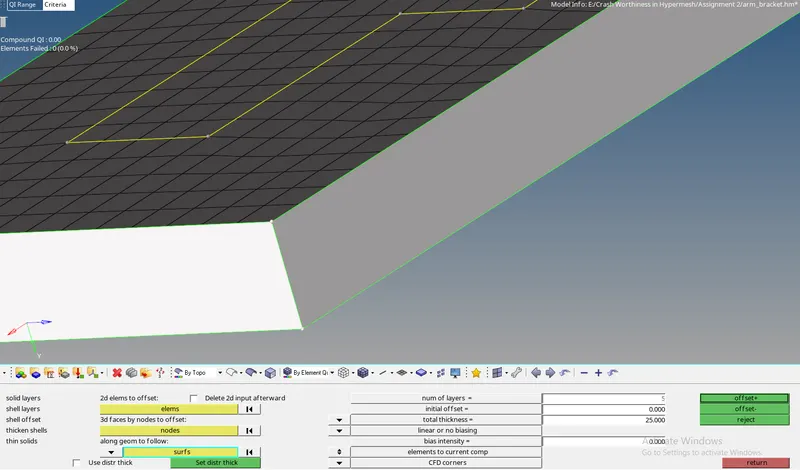
- In 3D Tab >> Select element offset Panel > Select solid layers >> Select the 2D elements to offset >> Select the number of layers 5 since the thickness is 25 >> Click Offset+.
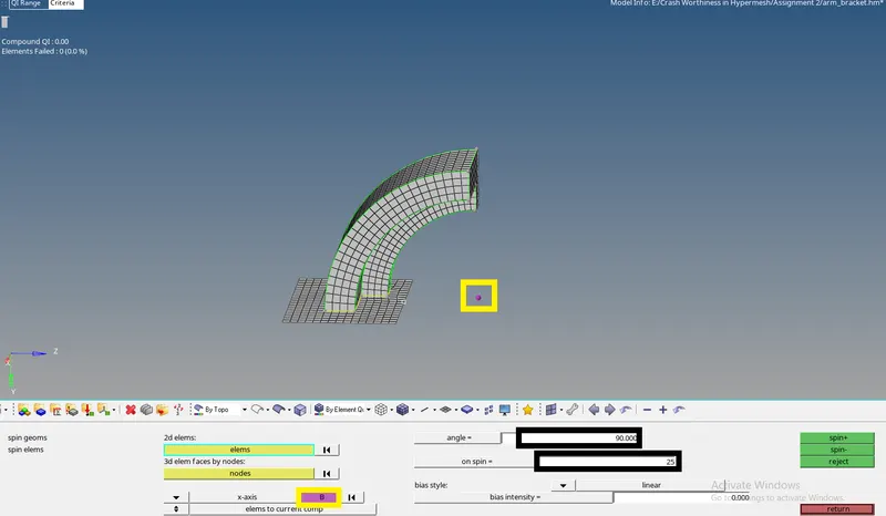
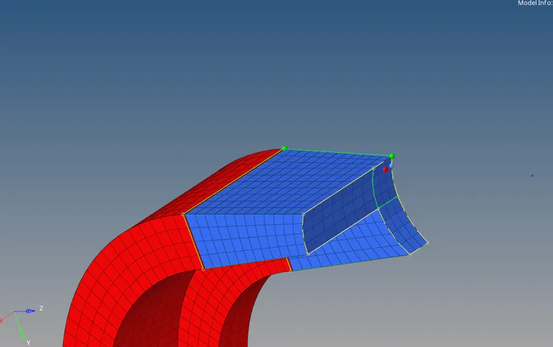
- To mesh the curved arm the SPIN tool can be used for Hexa along the arm.
- In order to use the spin tool, we need the center point for the curve to spin the mesh in the proper direction.
- Go to distance or Click F4 >> Select 3 nodes > select the nodes > Click on the Circle centre.
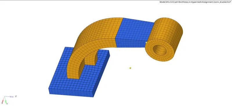
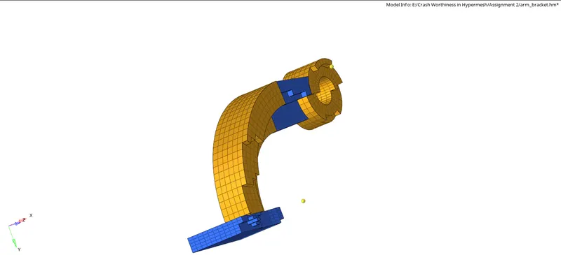
- Go to 3D Tab >> Click on spin panel >> Select the spin elements >> Give the Angle as 90 >>Give spin elements as 25 >> Select the 2D elements as the L shaped region quad elements that is the base of the curved arm >>Spin along Xaxis and base point as center node > offset
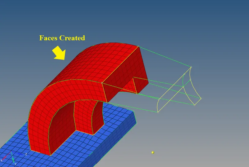
- Create the faces from the arm curve. Since the arm created is a 3D mesh and we need face elements as the base for the next arm part.
- Go to the Tools Menu >> Select faces >> Select the components >> Click faces
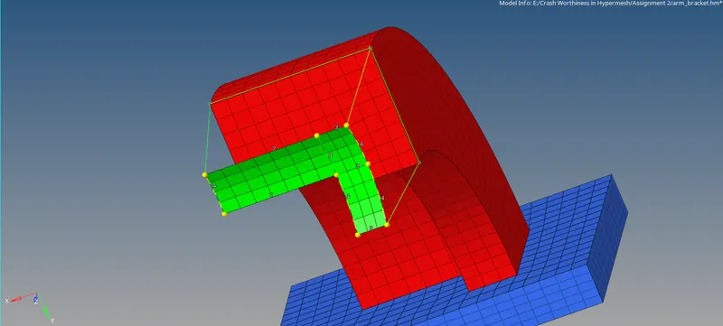
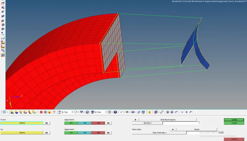
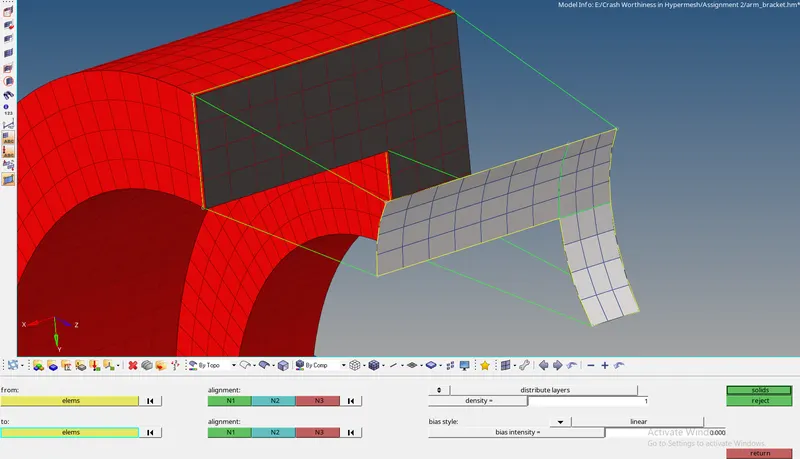
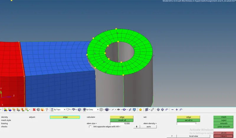
- Now create the 2D quad shell elements on the end face of the arm. Note the number of elements should match the elements on the other face.
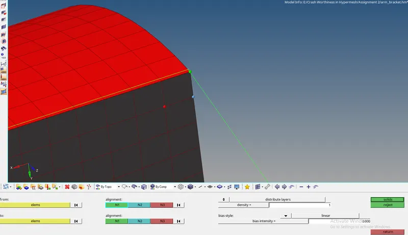
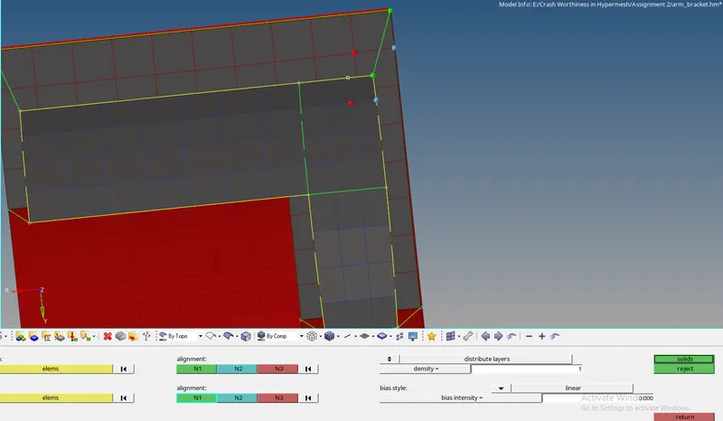
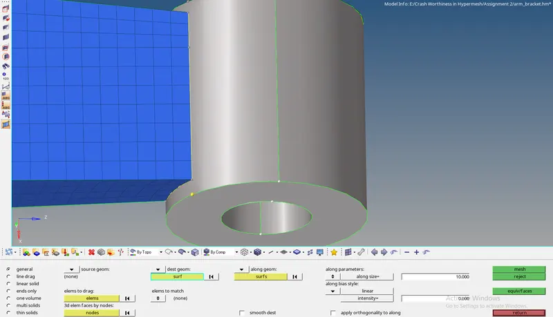
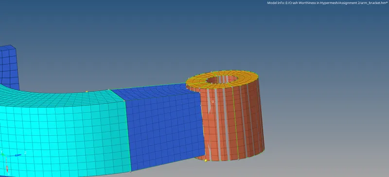
- Go to 3D Menu >> Select linear solid >> The alignment node should be the same on both the faces >> Select the Density as 12 > Click on solids.






For Connections:
- Opening the File:
- The File opening does requires few steps to be followed which then results in the opening of the file.
- The Model is of ‘.hm’ format, go to the Files>> Click Open >> Select the File >> Click Open.
- Generating the mesh:
- The mesh is already present in the given file, on the one end of the model. Therefore, they can be projected to the model as the model is similar. To move the FE elements, click Shift +F7 to project >> select to surface option >> Select the Elements >> Duplicate >> Click on the Surface to project >> Click Project.
- The Elements are projected.
- Giving the Connections:
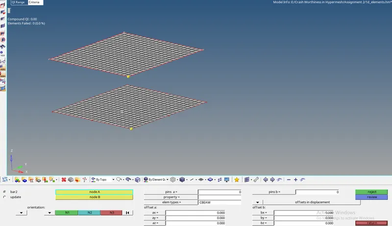
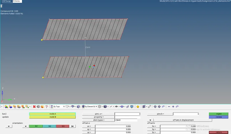
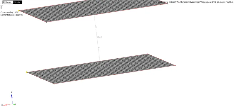
- For the Connection to make, Go to the 1D element Menu >> Click on the bars panel >> Select the nodes to which the connection needs to be made >> Give an Orientation >> Select the Element Type as BEAM3N >> The Connection is generated.
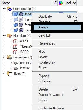
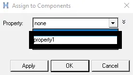
- To assign the Property and Material to the Connection. Right Click on the Connection component, Click on the Assign >> Give the Property card and Material card >> Click on Apply and Ok.
- Once the assigning is completed the following property and material are assigned to that particular component.
Questions:
- Check the material properties of the rail component and calculate the speed of sound in steel rail=_______
To Check the Rail component material Properties. Open the Starter File. While the Starter File is opened, the First Run of RADIOSS is seen. Check for the Steel material. Just the RHO_I, Note the value of density (`rho`) and Young’s Modulus (E) value at the same position can be found. Therefore, The Density and young’s modulus is noted as below.
`rho`= 0.0078
E = 210000.0
The Formula for calculating the Speed of the Sound is given below
`c= sqrt(E/rho`
`c= sqrt(210000/0.0078)`
c= 5188.745 m/s
The Speed of the Sound is 5188.745 m/s.
- The length of the rail is about 1000 mm. calculate the time takes for a shock wave to travel from one end of the rail to the other.
Given, The length of the rail is 1000mm I.e.
l = 1000mm.
The formula for the time taken for a shock wave to travel from one end to the other is given as below
`Delta T = l/c`
Where,
`Delta T`= Time taken for a shock to reach the other end.
l = Length of the Rail
c = speed of the sound
`Delta T = 1000/5188.745`
`DeltaT`= 0.1927248
3. Time for sound to travel length of rail= 0.1927248
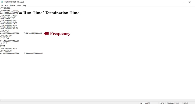
4. Edit the engine file so that the stress wave can be monitored, moving from one end of the rail to the other during impact -this will require a termination time equal to the time it takes for the sound to travel the length of the rail(set on/RUN card)
The Engine File is named as the “ *FIRST_RUN_0001.rad ”. Open the File.
Just Below the /RUN/FIRST_RUN/1/, Change the Value of the Process Time or Run Time or Termination time to the calculated Termination Time.
5. Set the frequency of animation output to a time that will give 20 animation steps(/ANIM/DT)
The frequency is calculated as below
`T_"Freq" = "Termination Time "/ "No. of Steps"`
`T_"Freq" = 0.1927248/20`
`T_"Freq"`= 0.00963624
The Frequency of the animation output to a time is 0.00963624
6.Change /print -10.
- Below the ANIM/DT line, the /Print-10 is already entered in the code.
Result:
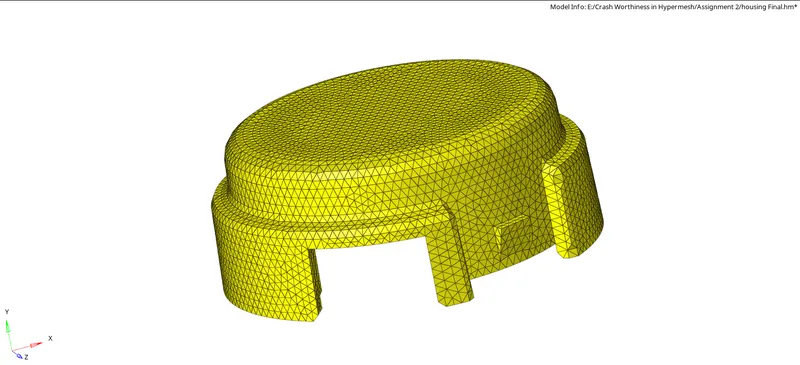
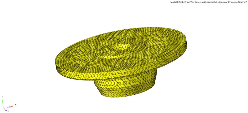
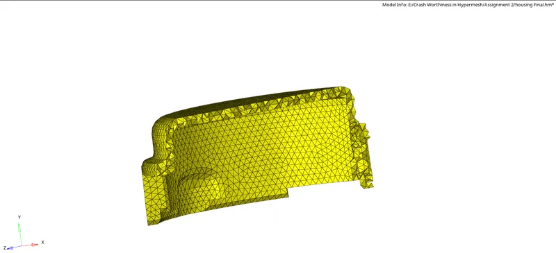
The Tetra and Hexa mesh are created. The 1D connections are given to the component given and the calculation is done using the formulas.
Tetra Mesh:
Hexa Mesh:
Connections:
Learning Outcomes:
- Learned how to create a Tetra Mesh and Hexa Mesh.
- Learned to Give a connection to a model.
- Learned to calculate and give and edit the .rad file to get the calculated output in the RADIOSS.