Assignment 2
Q1. When we open the "Starter file : FIRST_RUN_0000", we can get to see properties of a material as shown below,
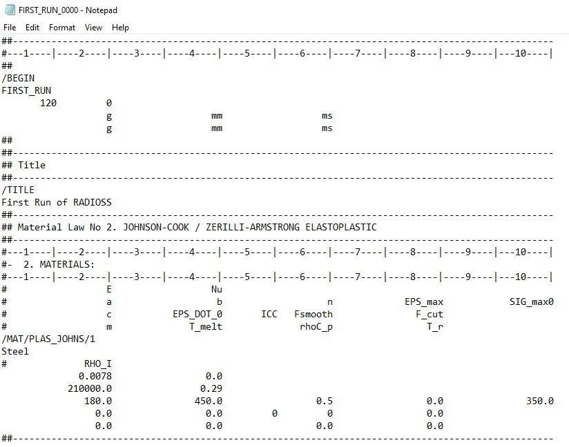
Young's Modulus of Steel : 210000 g/mm-ms^2
Density of Steel : 0.0078 g/mm^3
We know that "Speed Of Sound" = `sqrt(E/rho)` = `sqrt(210000/0.0078)` = 5188.74 mm/ms
So the speed of sound is 5188.74 mm/ms.
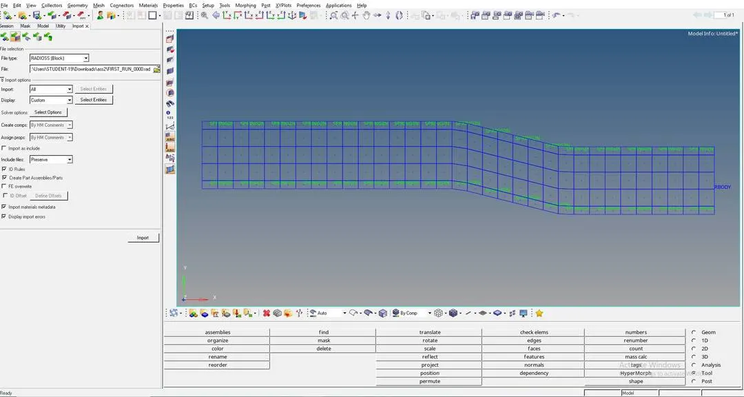
BEFORE DOING THE ABOVE CALCULATIONS WE HAVE TO IMPORT "FIRST_RUN_0000rad" file in the "HYPERWORKS", as shown below:
Q2. Given the Length of the Rail is: 1000mm
Time taken by the Shock Wave to Travel from one end of the rail to the other can be calculated by the below Formulae:
`Deltat = l/sqrt(E/rho)` = 1000/5188.74 = 0.1927ms
So, Time taken by the shock wave to travel from one end of the rail to the other is 0.1927ms
Q3. Time for sound to travel Length of Rail is 0.1927ms.
Q4. Here Engine File is edited so that the "Termination Time" or "Run Time" to be equal to the time it takes for the sound to travel the length of the Rail.
This is edited in "CARDS", in that we have to go to "ENG_RUN" and in that we have to edit in the "Tstop".
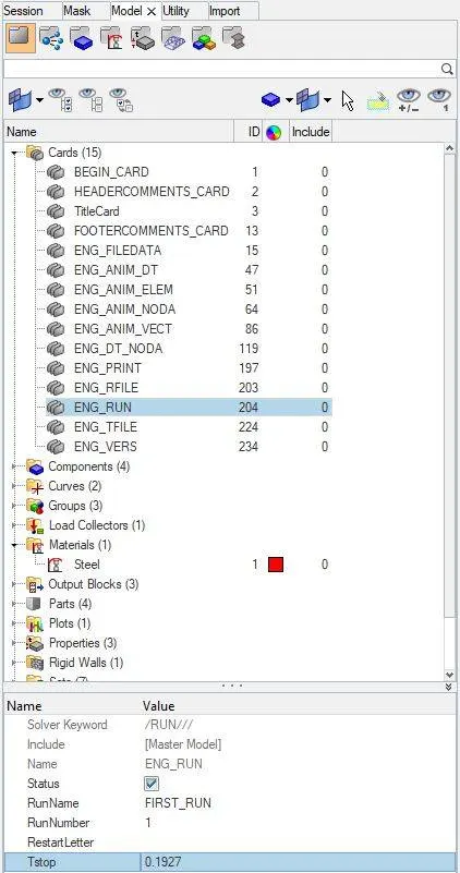
Q5. From the above Calculation the "Termination Time" or "Run Time" is 0.1927ms
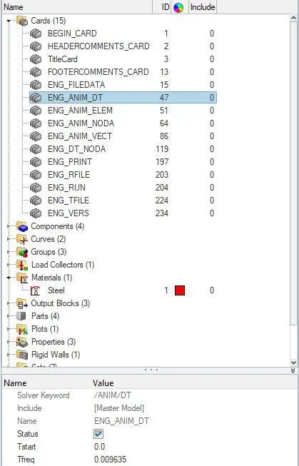
So, Frequency of Animation Output to a time that will give 20 Animation can be calculated by = (Run Time) / (number of animation steps required)
Frequency = 0.1927/20 = 0.009635
We set this frequency in "CARDS", in that we have to goto "ENG_ANIM_DT" as shown below:
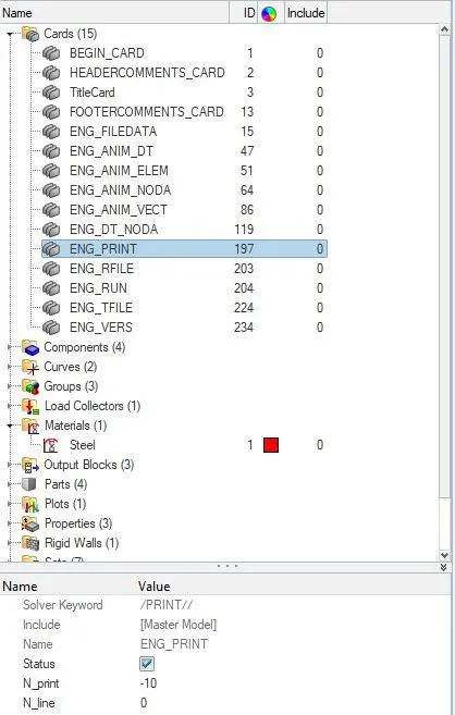
Q6. Here we have been asked to change "PRINT-10", this can be changed in "CARDS" and in that "ENG_PRINT"
but here, "print-1" has already been set as shown below:
Q7.
AIM:
To create 3D MESH for the given MODEL.
OBJECTIVE:
To create
A] "3D TETRA MESH" FOR "COVER AND HUB"
B] "3D HEXA MESH" FOR "ARMCURVE"
PROCEDURE:
A] 3D TETRA MESH FOR COVER AND HUB.
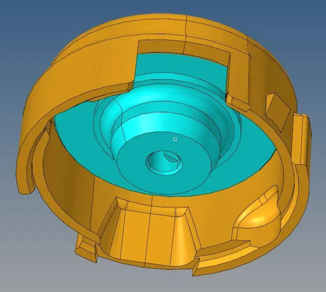
There are 3 methods to do 3D meshing for the given component, here we have used the tool "UTILITY".
1) First we have to open the given ".hm" model in "HyperWorks 2020".
2) We have to set the Quality Criteria "TET COLLAPSE" as "0.15" by going to 'Tools' > 'Check elements' > '3D', In 3D we have to set "TET COLLAPSE" as "0.15".
3) For doing "TETRA MESH" we will follow the below procedures:
'Views' > 'Browser' > 'Hypermesh' > 'utility' > Inside utility we have to select "GEOMETRIC MESH" >Inside this GEOMETRIC MESH we have to select "QUICK TETRA MESH" > 'In this we have to set "MESH SIZE" as 5mm, "MINIMUM TRIA ANGLE" as "20 degree" and "MESH DENSITY" as "UNIFORM" > Now hit "MESH"
The good thing about this tool is that it does some geometry cleanup before going for 2D and then 3D, so now we have "TETRAMESH" created.
4) We have to follow these above steps for both "COVER" and "HUB", these two components have to be separately mesh.
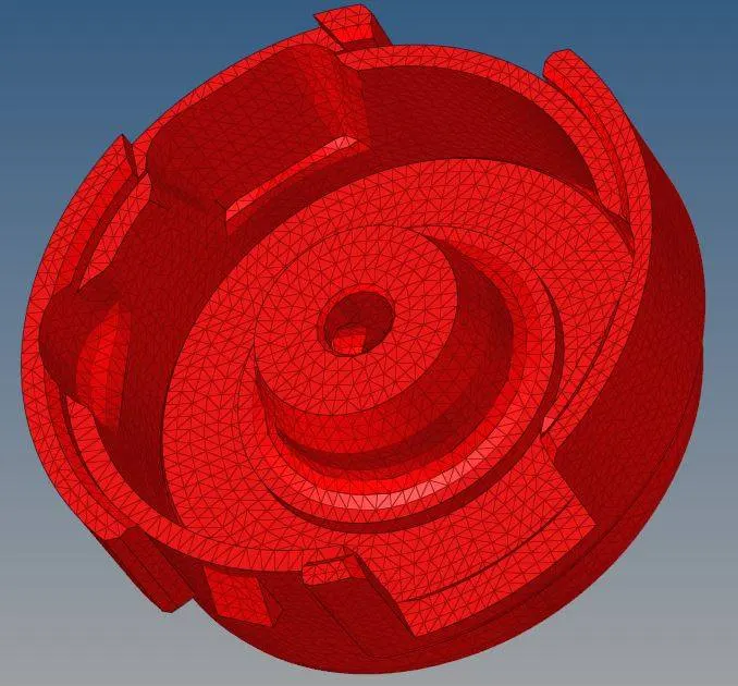
5) The below snap shows the "TETRAMESH" on both "COVER" and "HUB".
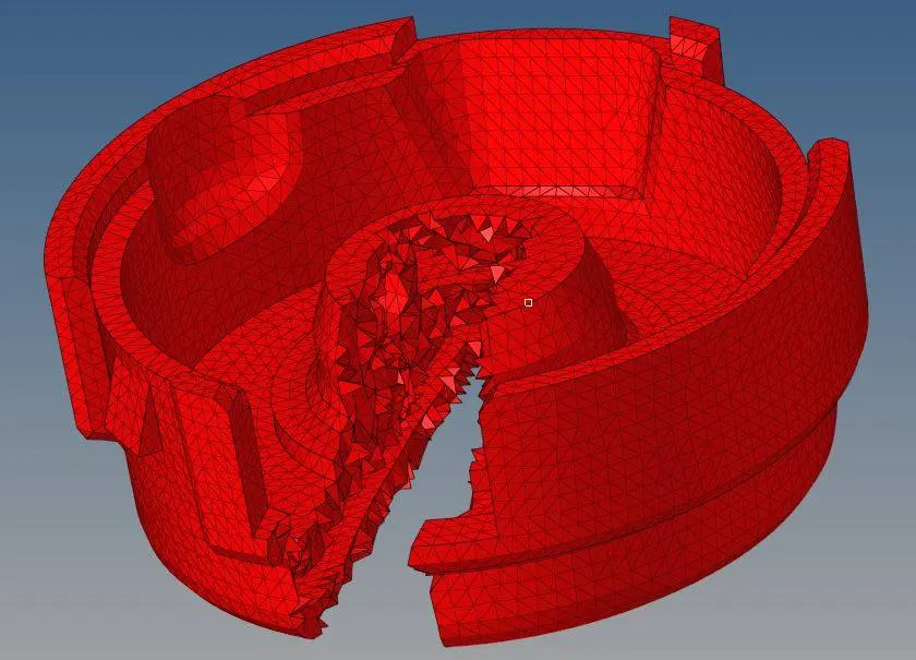
6) The below figure shows the "MASKED" OR the crossection of "COVER AND HUB"
B] 3D HEXA MESH FOR ARMCURVE.
Here we have 4 diffrent parts to be meshed seperatly because of there difference in structure, here we have "BASE", "ARMCURVE", "ARMSTRAIGHT" and "BOSS".
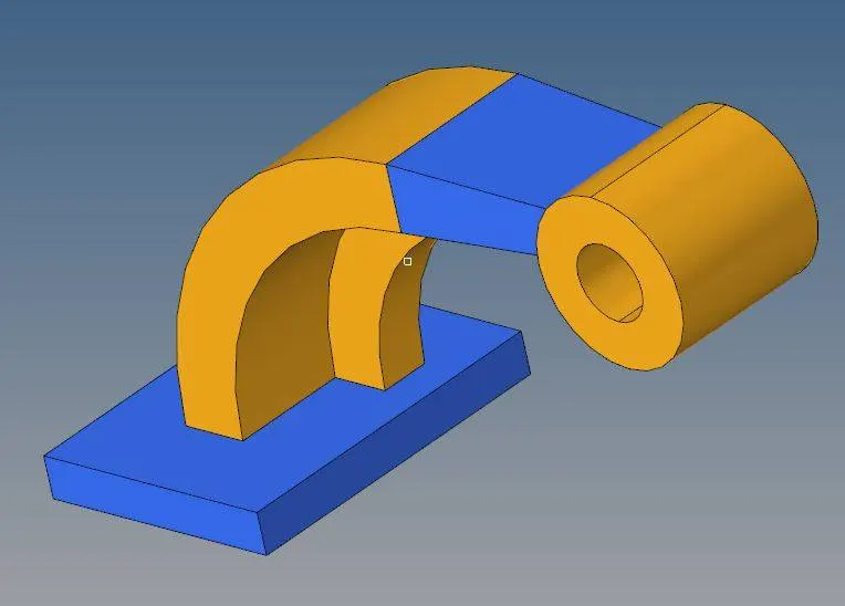
FIRST WE WILL START MESHING FROM BOTTOM THAT IS "BASE":
1) To start the meshing exercise, first we have to create a 2D mesh on the top of the base, while doing the mesh process on the "BASE" we have to hide evry other part in this component.
This 2D meshing is usually done by pressing F12 [shortcut for automeshing], now select the surface which needs to be meshed and hit "Automesh", now mesh is created on top this "BASE". As shown in the below figure, here instead of using "MIXED" in the element type , we have to use "QUADS ONLY", to avoid "PENTA6" elements.
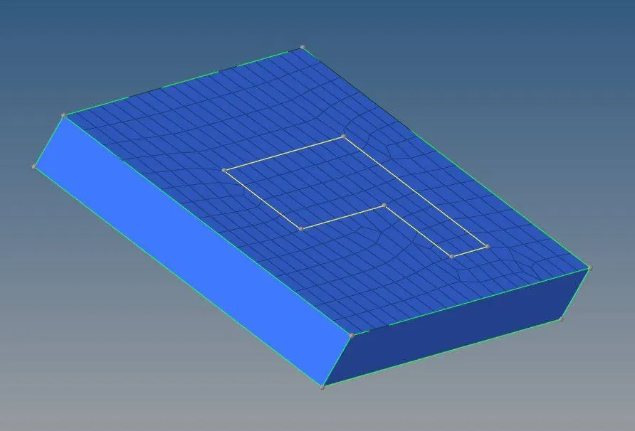
2) After thid 2D mesh we have to do 3D mesh for this "BASE", to do that we use a tool called "ELEMENT OFFSET", So to do 3D mesh we will follow the following procedure:
Goto '3D' > 'element offset' > 'Select Solid layers and in that "elements to offset:elements" now select the 2D elements on top of the BASE' > 'For along geometry to follow we have to select side surface of the component > 'Total thickness should be denoted 25mm and number of layers should be denoted 5mm' > 'Hit = Offset+'.
now 3D mesh is created for the "BASE" as shown below:
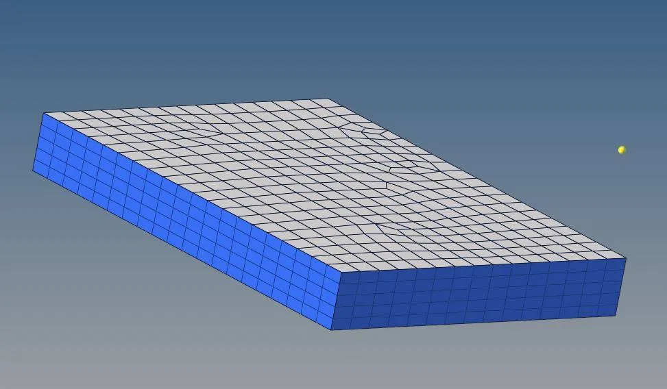
SECOND WE WILL START MESHING THE "ARMCURVE":
1) Here we have to retain the 2D mesh of the "BASE" and hide 3D mesh of "BASE"
2) Goto '3D' > 'Spin' > in that opt for "spin elements" and we have to denote values for both 'Angle:90 degree' and 'Spin:25' [this depends on what density we want]
3) Here it asks for a "Normal direction to the plane" or "Plane definition", to do that we need the center point of the given curve for that we can use "F4", and then for "Plane definition select : x-axis" and then select the center point of the circle.
4) Then hit "SPIN -"
5) Now 3D mesh is created on the "ARMCURVE", as shown below:
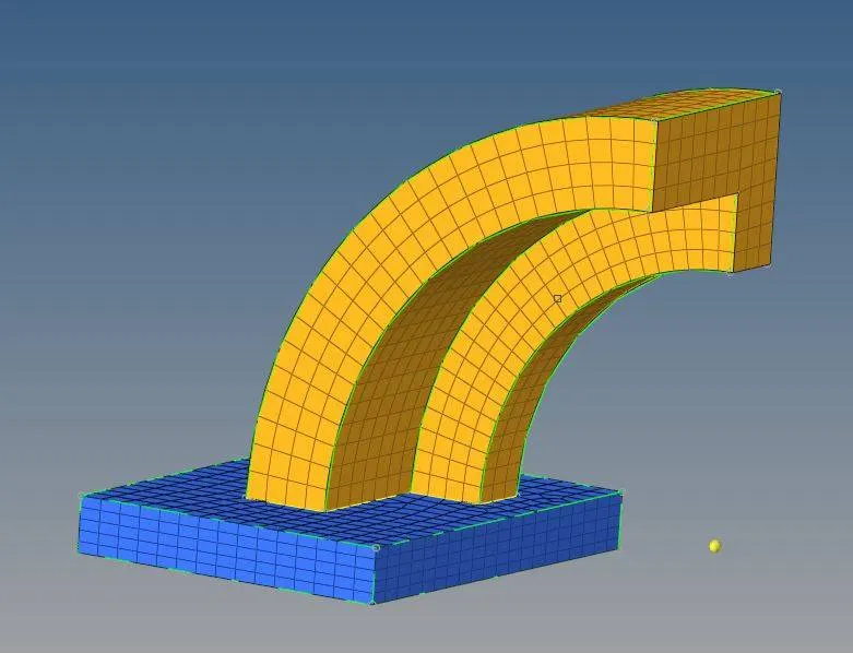
THIRD WE WILL START MESHING THE "ARMSTRAIGHT"
1) Goto '3D' > 'LINEAR SOLIDS'
2)Here we need the faces of the previous parts, that is we need faces of "ARMSTRAIGHT", to do that : 'Tools' > 'Faces' > Opt for components and select "Armcurve" and hit "Find Faces", this creates the faces of the components.
3) For creating linear solids we want a " Source element group" and "Destination element group" as well, so we have to create mesh on the face of destination, this is done by usins "Automesh" [F12]
4) Goto '3D' > 'LINEAR SOLIDS' > Select all the elements from the "Source surface" > And then select all the elements from "destination surface" > Then select 3 nodes on the source side and then select the exact same equivalent nodes on the destination as well > Now select the "DENSITY" as 12.
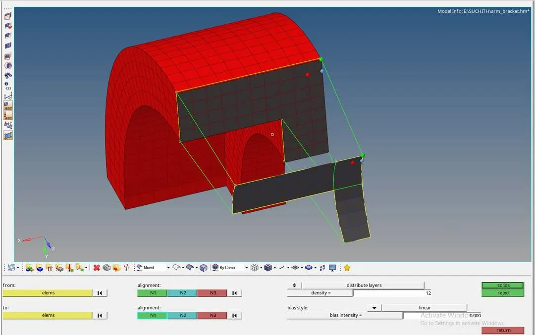
5) Now hit "SOLIDS"
4) 3Dmesh is created on the "ARMSTRAIGHT" as shown below.
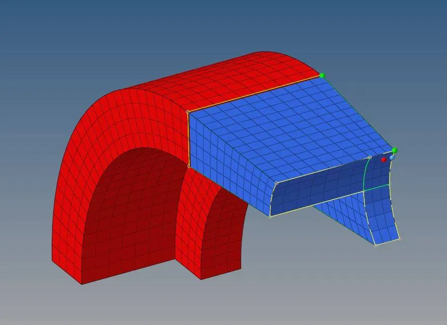
FOURTH WE WILL START MESHING FOR THE "BOSS"
1) So for that we always need a source geometry and destination geometry.
2) First we mesh one side of the "BOSS", As shown below:
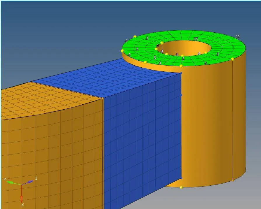
3) Then goto '3D' > 'Solid map' > opt for "general" and opt 'source geom:none', 'Dest geom: select the other side of the boss whre its not meshed' and 'Elements to drag: select all the meshed elements to be draged', 'Along geom: select Mixed' in that select all the nodes in the node path and select the appropriate line along the geometry' > 'along parameters: element size should be 10'
4) Hit "MESH", now 3D mesh is created as shown below.
5) After all these meshing we need to delete all the 2D elements along the way which we created.
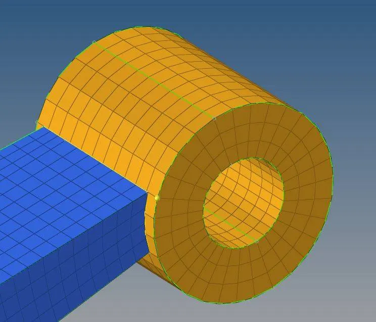
Below figure shows the 3D meshing of the whole component.
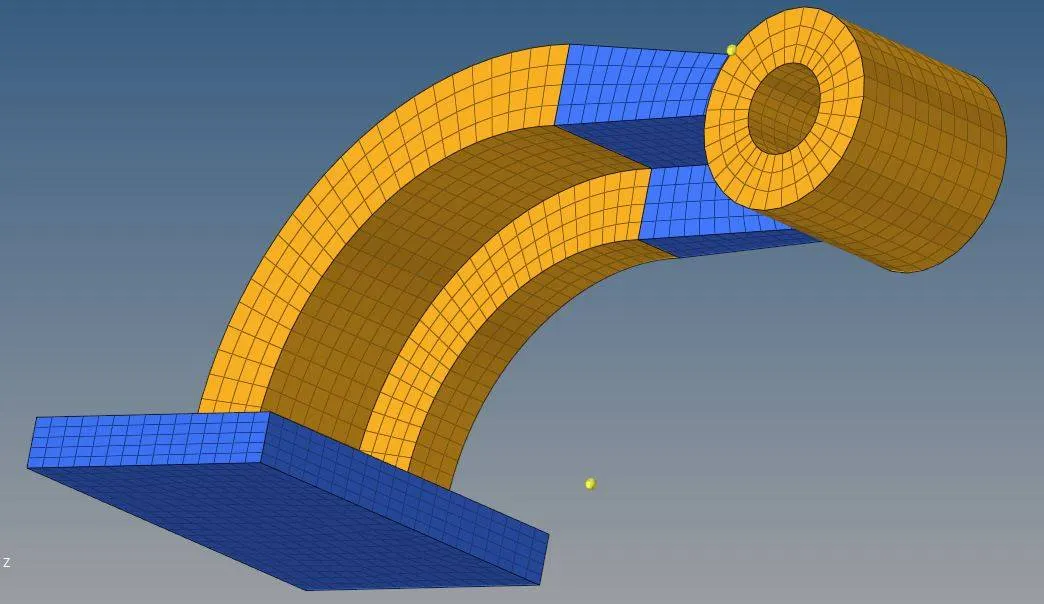
CONCLUSION:
Hence, 3D meshing is done on the given component, they are:
- Created 3D "TETRAMESH" on "COVER AND HUB" With Target Tet Size as 5mm and "TET COLLAPSE" is set as "0.15".
- Created 3D "HEXAMESH" on "ARMCURVE" With Target Hex Size as 10mm and "TET COLLAPSE" is set as "0.15".
- And Checked for "TET COLLAPSE" in both the models.