Assignment 11
Assignment 11
- Tutorial- single cyl DI add case 2 with discretization length 0.1 mm for intake runner and compare with default case 1
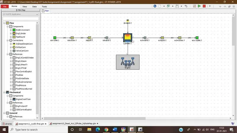
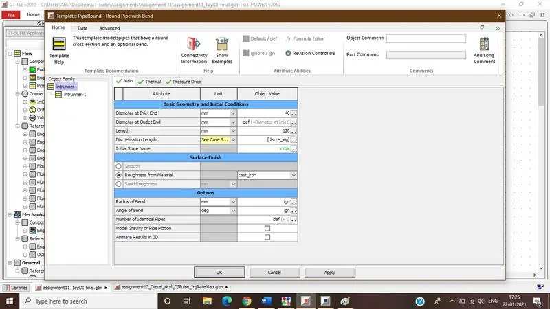
Creating discretization length as a parameter we can add the desired cases with variable discretization length.
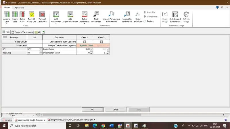
Two cases are created for comparison in which case 1 is run with the default values of parameter and case 2 is with discretization length 0.1
Results and Discussion:
Variation in the results due to change in discretization length is shown below
Pressure Plot
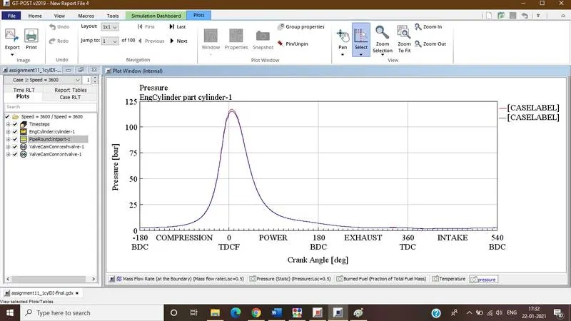
If we take look at pressure plot then for the both cases it is almost same so we can say that pressure is only depend on engine speed.
Fuel Burn Rate
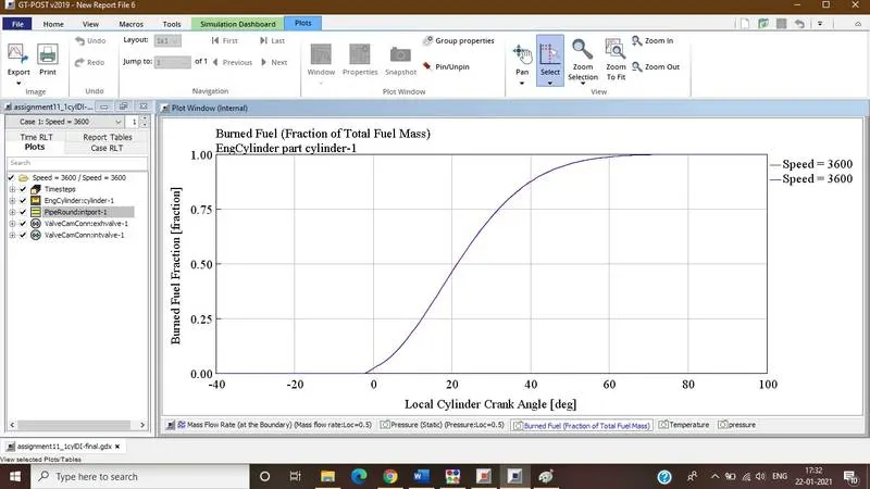
Fuel burn rate is also depending on the engine speed and not on discretization lengths. Burning rate increases at combustion stroke i.e., power stroke.
Mass Flow Rate
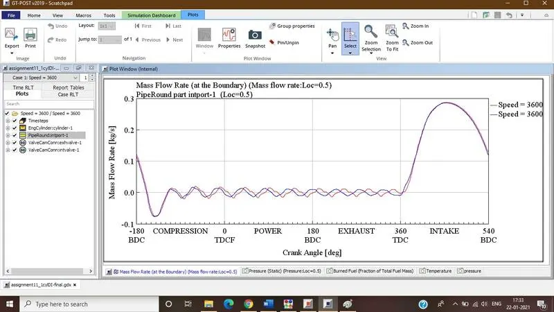
Mass flow rate shows slight variation with the varying discretization length which gives a more accurate results
Static Pressure
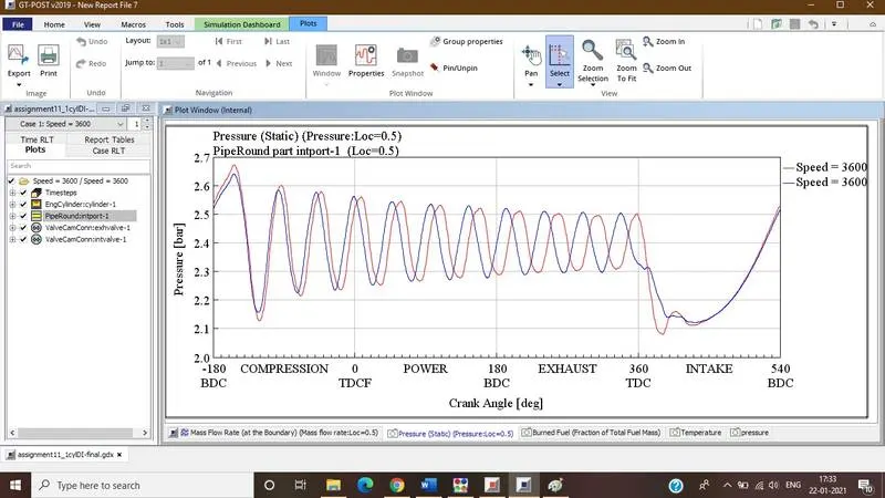
case 2 gives us more accurate results over case 1
Temperature Plot
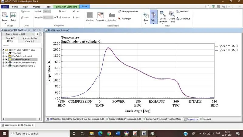
Temperature is depending upon engine speed and not on discretization lengths. That’s why temperature is same for both the cases. It is maximum at power stroke and minimum at intake stroke as shown in above plots.
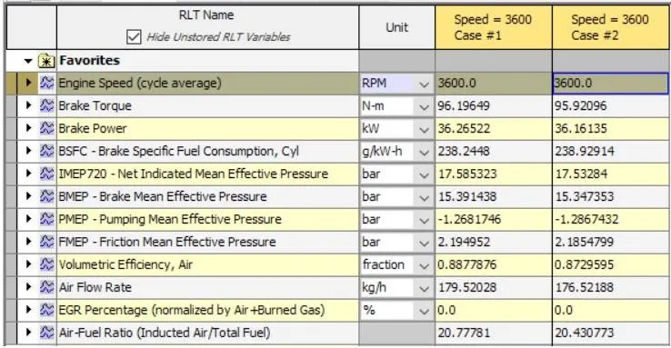
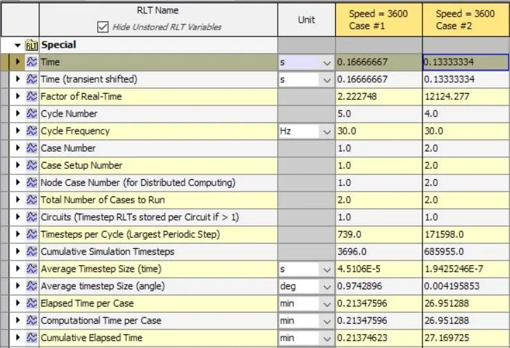
Discretization length % Diff. w.r.t 40 mm
|
Parameters |
40 mm |
0.1 mm |
|
|
Torque (N-M) |
96.19 |
95.51 |
- 0.31 % |
|
BSFC (g/Kw-H) |
238.24 |
238.91 |
0.29 % |
|
Max Pressure (bar) |
117.11 |
115.18 |
- 1.65 % |
|
Final RLT Interval |
6.35 |
9480.69 |
149202.20 % |
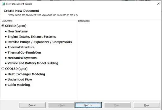
- Explore tutorial no 2 (GEM3D) - “Building intake manifold from STL model” Start SpaceClaim and import phelum file
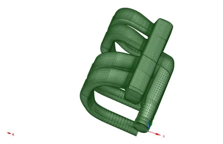
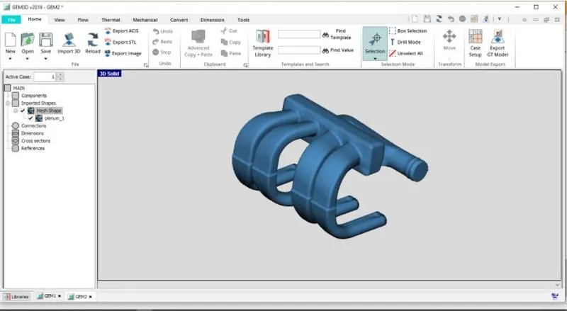
Step 1- Separating Sections by Curves
Notice that the inlet and the ends of the 4 intake runners are closed. We need to remove these caps so the ends are open and available for flow. To do this, we will use the Separate by Curves operation. This will separate the geometry into parts based on changes in the surface of the object. This process will also separate the intake runners into two different sections near the area change at the top of the runners. Ensure the part is selected and choose Separate by Curves from the Shape Operations group in the Convert tab. The tolerance controls how sensitive this operation is to changes in the surface area of the part. A Tolerance of 1.0 should be used for this operation. Click OK.
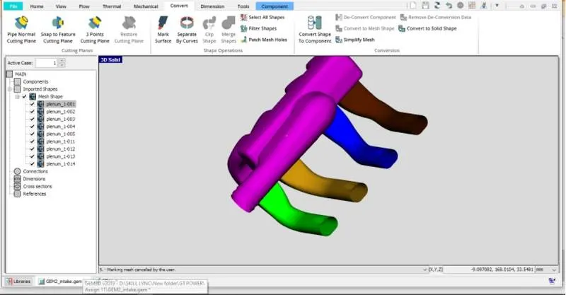
Dive this flow into small volumes. Go to convert and select geometry and select separate by curves. and delete inlet and outlet faces to convert existing body into water tight body.
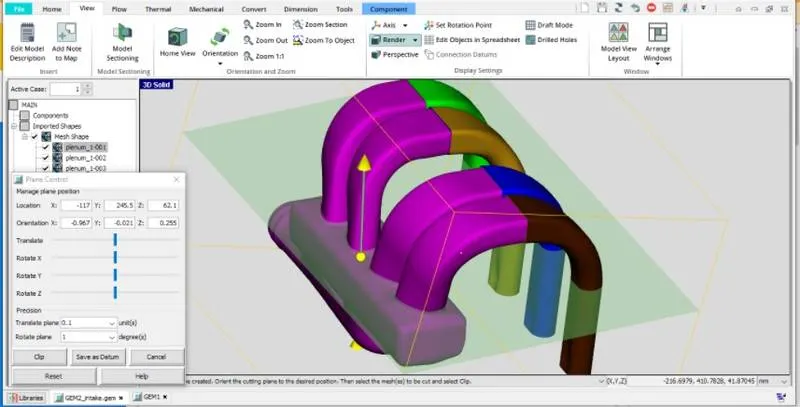
Step 2- Using the Cutting Plane
create plane using 3 point cutting tool from convert
Step 3 - Convert shapes into GT power components
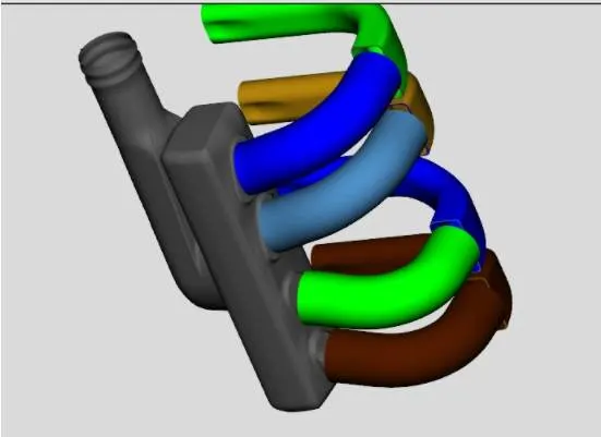
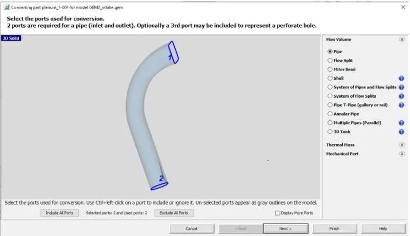
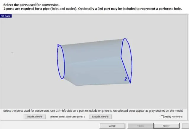
Once we have sections that can be represented by pipes or flow splits, we need to convert them into flow components. This is done with the convert mesh operation. To begin the conversion, right-click on the first section of the first runner (grey coloured bent section in the image above) and select Convert Shape to Component. This will open the convert mesh window, shown in the image below.
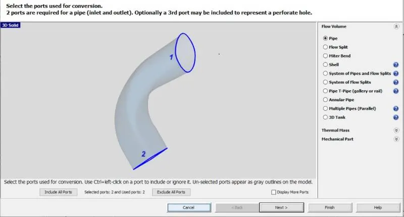
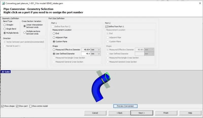
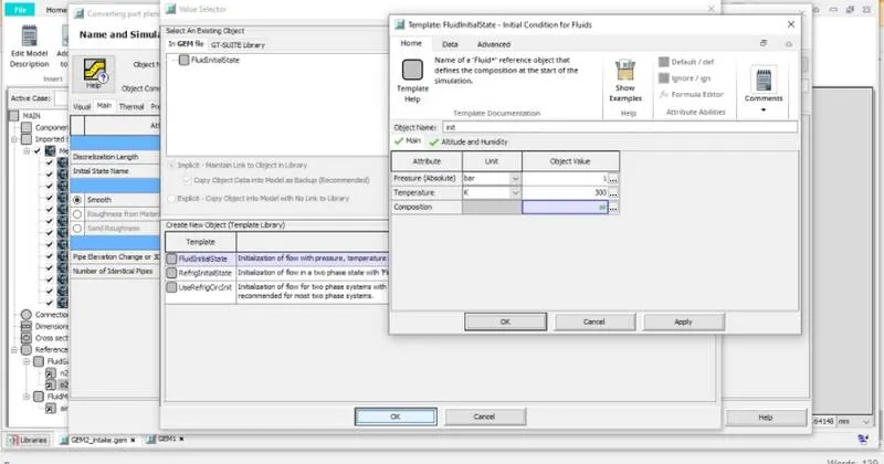
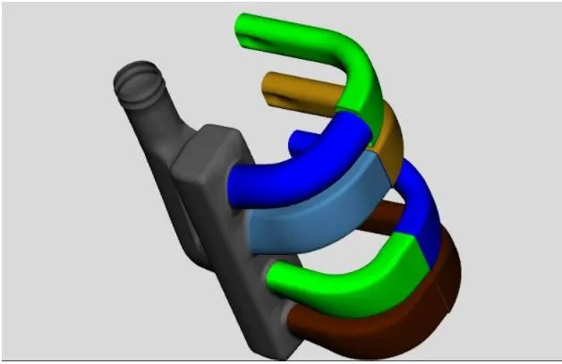
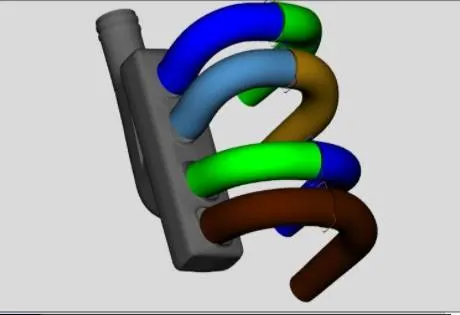
same stapes applied for other 3 pipes and the result is shown below
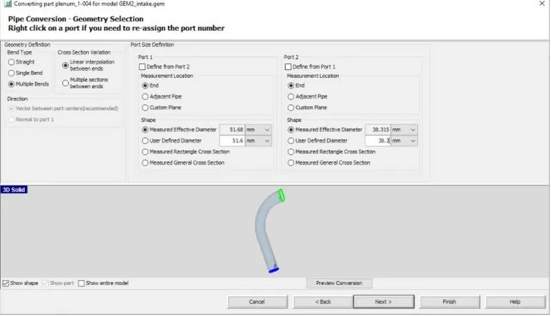
To convert other end of pipe.
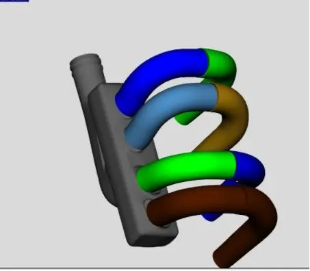
Step 4- Adding a Custom Connection
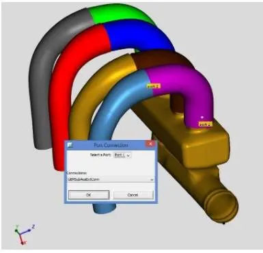
In the conversion process for the runners, information regarding the curved entry from the manifold (fillets) was lost. This curved entry would represent a better flow transition than a default orifice connection, so we need to manually add an orifice connection to represent this. To add a custom orifice to a flow component right-click on the first section of runner 1 (blue component in the image above, "run1-1") and choose Add Connection. This will open the port connection window, shown in the image below, that allows the selection of which port to add the connection to and what type of connection to use.
Step5 - Set Value to Forward Discharge Coefficient - Parameter
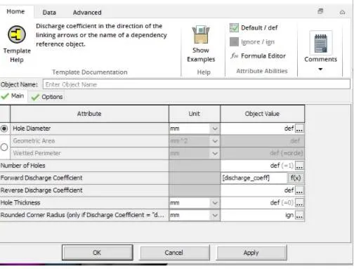
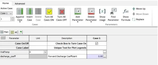
With the connection template open, we can give it a name of "ori-run1". To account for the curved entry, we want to modify the forward discharge coefficient (essentially make it higher than it would normally be for an abrupt area change). Since all 4 runners likely have the same curved entry shape, they should all get the same discharge coefficient. Therefore, define a parameter named [runner-cd] for the Forward Discharge Coefficient attribute. The component window should now look like the image below.
Repeat for all runners
Step 6 - Add Subassembly connection to Impose Connection
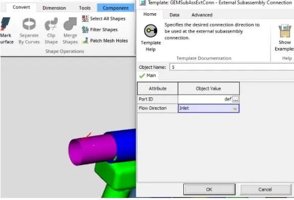
Direction Make Port 2 of the runners as outlet for GT to understand. The ends of each runner need an end connection specified. This is done with a special subassembly connection. To add the subassembly connection right-click on the end section of the first runner component ("run1-2") and choose Add Connection.
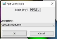
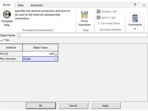
Repeat the same for the remaining runners.
Step 7 - Divide pipe section with Area Changes
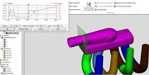
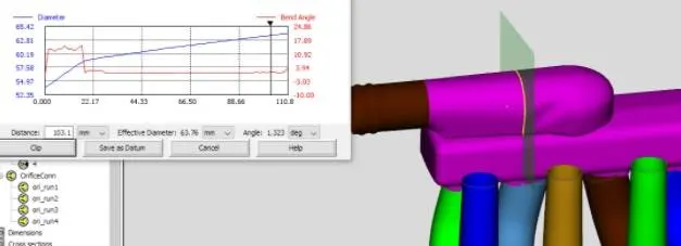
Now that we have the runners converted, let's move to the other end of the manifold. The entrance appears to consist of a pipe section with a round and D-shape, then a 90 degree turn into the manifold. The straight section can be converted into 2 pipes, one representing each effective diameter. Therefore, we need to cut and separate these two sections so they can be converted. Since they are pipe sections, we can utilize the pipe normal cutting plane operation. From the Cutting Planes group in the Convert tab, choose Pipe Normal Cutting Plane. To place the cutting plane, click on the rounded outer wall of the model very close to the entrance. This will place the pipe normal cutting plane at that location and in an orientation that is normal to the flow direction, as shown in the image below, as well as open the pipe normal plane window.
Step 8 - Making more Difficult Cuts
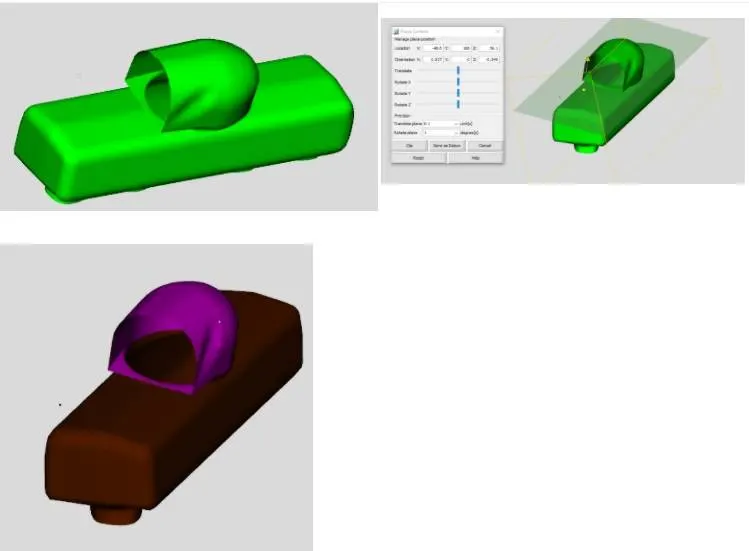
The next step is to separate the manifold from the 90-degree entrance flow split. This must be done with the cutting plane operation, but will require use of some advanced features of that operation. The goal is simple, cut off the top flow split section without cutting through the manifold itself. This will be a multiple step process as we will need to place the cutting plane, rotate it to the correct orientation, and translate it into the correct location.
Step 9 - Determining Orientation During Conversion
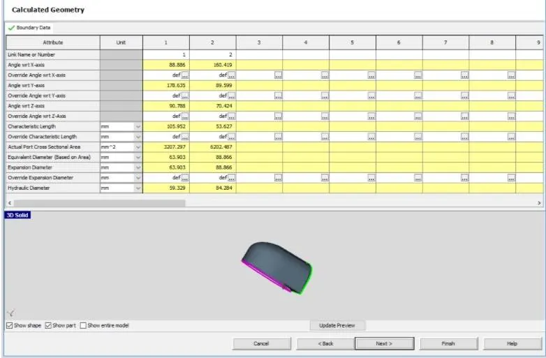
Next convert the centre section into a flow split. Right-click on it and select Convert Shape to Component. Select Flow split from the select the conversion geometry pane.
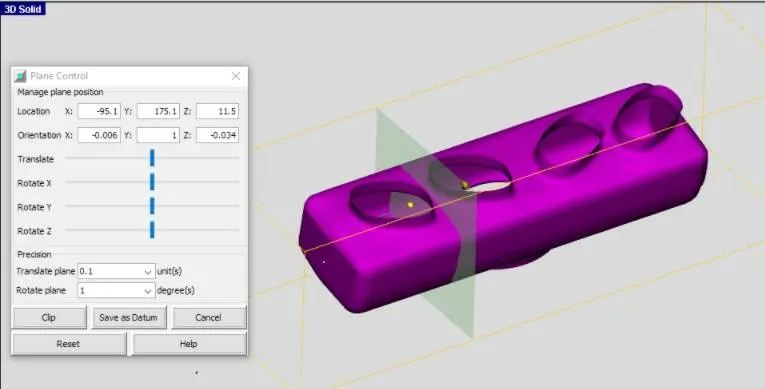
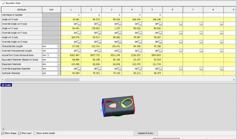
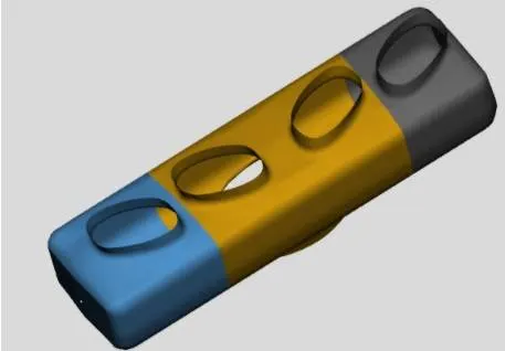
Step10 - Flow Connections
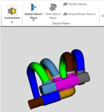
The gaps between the pipe and plenum needs to be closed using extruded connections from connection option is taskbar. Select Flow Connection > Flow Connection from the Connections group under the tab Flow. This will show available surfaces for adding flow connections and repeat for extrude connections to close the gap.
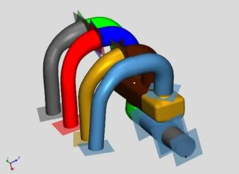
Step11 - Discretize the Model
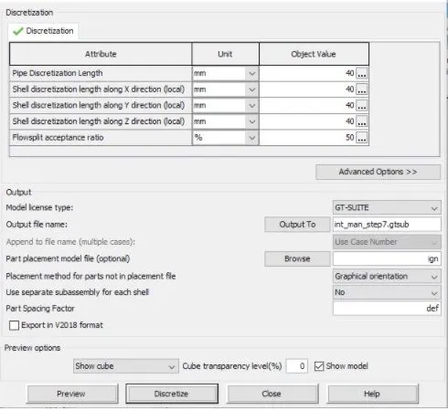
First orient the model and then click the Discretize button and GEM3D will create a GT-SUITE model file (. gtsub).
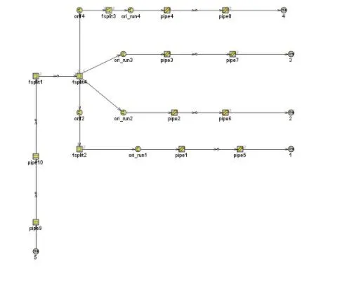
3D to 1D converted model
After aligning all the connection in a straight line, we obtain flow circuit shown below.