Assignment 11
AIM :- To study the discretization length and Building intake manifold from given STL model.
OBJECTIVES :-
Given project has following objectives-
- Solve single cylinder DI with different lengths for intake runner.
- Compute Torque, BSFC, maximum cylinder pressure and simulation time
- Explore the planum STL model in GEM3D.
SOFTWARE USED :-
Following different softwares used in this project are-
- Spaceclaim v2019 -> To drop and drag CAD model
- GEM3D -> To setup the different setting
- GT-ISE v2019 -> To converting 3D model to 1D model and run the 1cyl DI engine.
THEORY AND INTRODUCTIONS :-
Two types of theory are described, with the purpose of predicting the acoustic transmission loss of lined plenum chambers (which are sometimes used as attenuators in air conditioning duct systems). The first kind of theory embodies a low frequency wave acoustic approach, and two separate models are evolved: one is for a single plenum chamber, and the second is for a plenum chamber incorporating one or more acoustically lined baffles. The other type of theory is valid at high frequencies, and is based upon geometrical (or “ray”) acoustics. This is applied to a single chamber and to chambers containing either one or two lined baffles. Both the high frequency and low frequency results are reasonably simple. A limited amount of experimental data is also presented, as justification for the validity of part of the theory.
Planum STL model :-
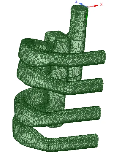
Procedures to converting Plenum 3D CAD model to 1D model are as follows-
- First off all open the tutorial Plenum CAD model into spaceclaim v2019.
- After extracting model here import into the GEM3D software for descretizing into small small parts.
- For converting our model into 2 parts use the option “seperate by curves” in convert
- Delete the inlet & outlet caps.
- By using 3-point cutting tool in convert menu seperate the each runner.
- Then convert each runner into pipe by right clicking on each component and selecting “Convert shape to components”.
- After converting pipe specify the inlet & outlets of orifice shape by right clicking and selection add connections.
- Selecting normal pipe cutting tool convert tapper pipe into straight line pipe.
- Specify the pressure=1bar, temperature=300k and fluid is a air.
- For filling the gap use the option flow connection in flow menu.
- Then align the model proparly so that GT power can show the simple connections.
- Then Export into the “Export GT model”.
- In GT power we can connect this model to any connection and run the case.
Following are the some snapshots which are showing the Plenum 3D model into the 1D model are-
1. After deleting opening & exit caps :-
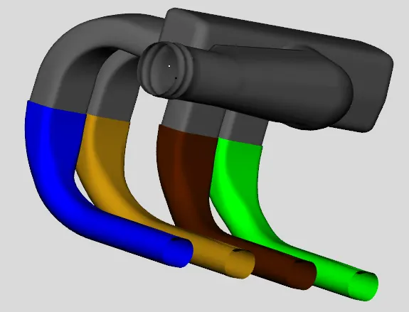
Here we can see that intake and outlet caps are deleted to showing the fluid flow.
2. After converting channel to pipe :-
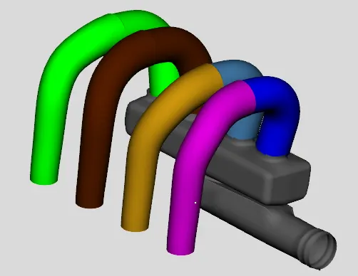
Here we can see that channel converting to pipe.
3. Seperated by curves :-
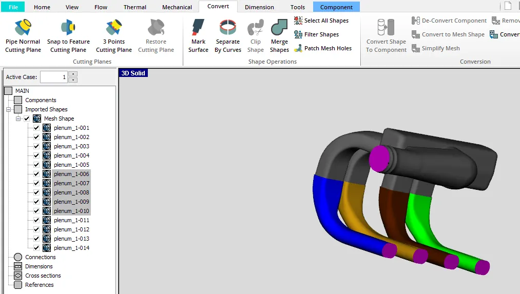
Whole runner converted into to halves for the discretizations.
4. Convert plenum part to pipe :-
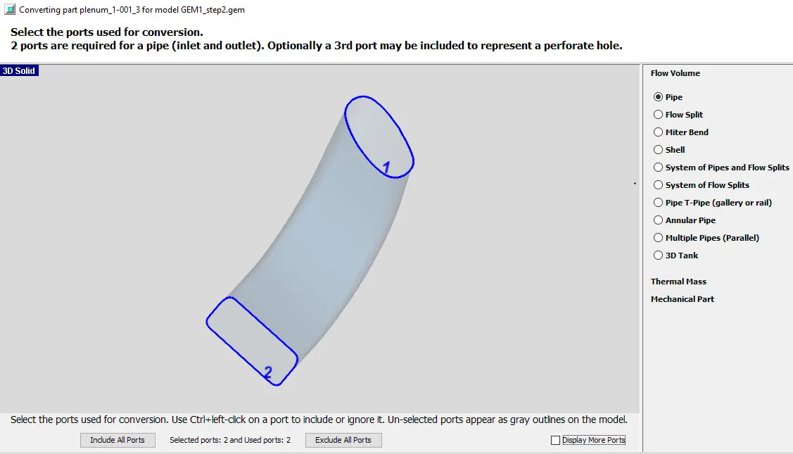
Here keep in mind that numbering of inlet and outlet part and select pipe go ahead.
5. Pipe geometry :-
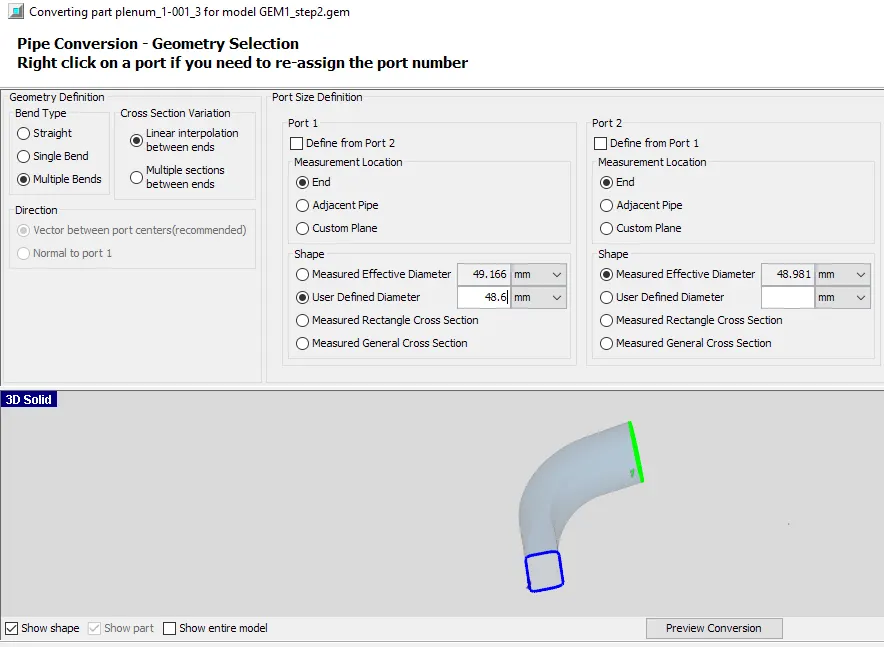
Here specify the propar diameter for port-1 and for port-2 select the define from port-1 option in most of the casses.
6. Initial condition of fluids :-
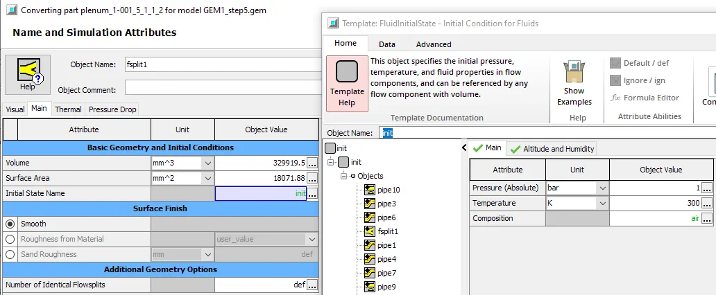
Here specify pressure, temperature and composition according to given figure.
7. Pipe normal plane :-
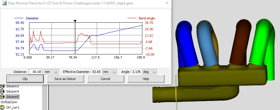
Here cut the pipe according to given figure.
8. Cuts the points by using 3 points :-
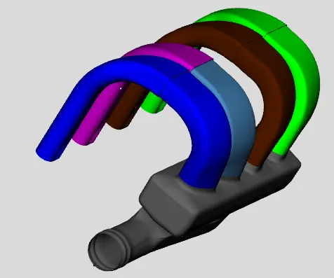
Cut the channel by using 3-point method.
9. GT Exporting :-
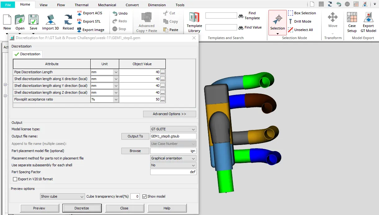
After discretization completion export the 3D geometry into GT-ISE v2019 which is 1D geometry.
10. Final geometry in GEM3D :-
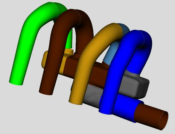
This is the final geometry after discretizations
11. Planum model converting 3D to 1D :-
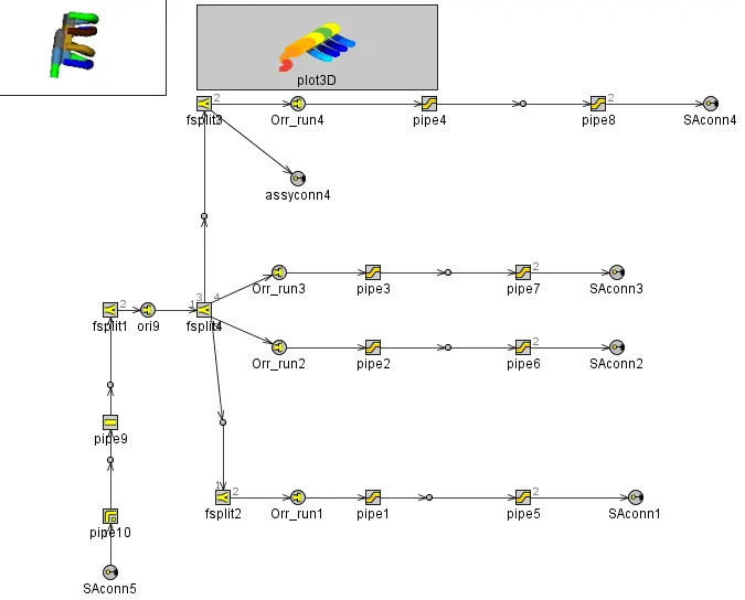
This is the connecting linkage of 1D plenum geometry.
2) Single cylinder DI :-
1. Model selection :-
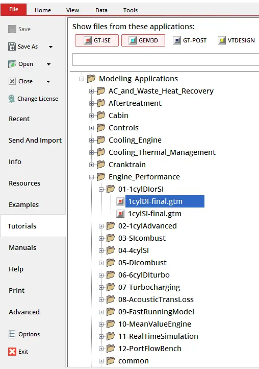
Select the model following ways-
“ File -> Tutorials -> Modelling applications -> Engine performance -> 1cylDI-final.gtm”.
2. Model :-
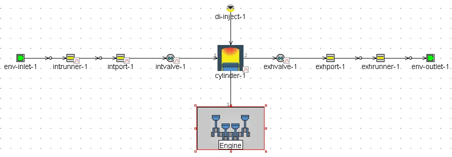
Setup the intake runner from given model and all settings are kept constant.
3. Intake runner geometry :-
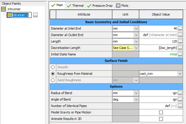
Here create the parameter for discretization length so that create the second case in case setup.
4. Case study :-
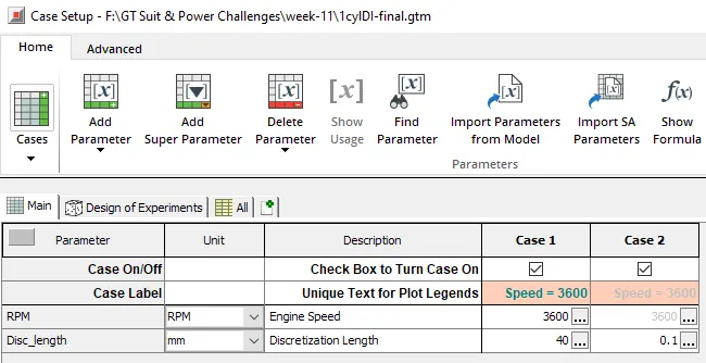
Engine speed kept constant and discretization length change for comparing the output.
SIMULATION RESULTS :-
Step-1 :-
MAIN DRIVER: Case# 1 Period# 1 Freq/RPM=60. 3600. Time=0.0
Cylinder 1 starting cycle 1
Flow Step 20, dt = 4.630E-05, t = 8.93999E-04
Flow Step 40, dt = 4.630E-05, t = 1.81993E-03
Flow Step 60, dt = 4.630E-05, t = 2.74585E-03
Flow Step 80, dt = 4.630E-05, t = 3.67178E-03
VOLEF IMEP Pmax Ieff REScs FAeff
cylinder-1: 0.898 17.21 78.81 39.3 0.0 0.0643
ENGINE: IMEP = 17.21 bar, VOLEF = 0.898 VOLEFm = 0.898
Flow timesteps/cycle=740, average time step = 0.973 deg
Time step restricted by
82.3%: Flow Control Settings
17.4%: exhrunner-1
MAIN DRIVER: Case# 1 Period# 2 Freq/RPM=60. 3600. Time=3.333333E-02
VOLEF IMEP Pmax Ieff REScs FAeff
cylinder-1: 0.888 17.61 117.31 40.2 2.2 0.0479
ENGINE: IMEP = 17.61 bar, VOLEF = 0.888 VOLEFm = 0.888
FLOW STEADY STATE:
NO Mass Flow (%) = 28.7413 at con : 4
NO Pressure (%) = 3.0622 at cmp : exhrunner-1
Flow timesteps/cycle=739, average time step = 0.974 deg
Time step restricted by
82.0%: Flow Control Settings
17.8%: exhrunner-1
MAIN DRIVER: Case# 1 Period# 3 Freq/RPM=60. 3600. Time=6.666667E-02
VOLEF IMEP Pmax Ieff REScs FAeff
cylinder-1: 0.888 17.59 117.12 40.2 2.7 0.0481
ENGINE: IMEP = 17.59 bar, VOLEF = 0.888 VOLEFm = 0.888
FLOW STEADY STATE:
NO Mass Flow (%) = 0.5252 at con : exhvalve-1
YES Pressure (%) = 0.0877 at cmp : exhport-1
Flow timesteps/cycle=739, average time step = 0.974 deg
Time step restricted by
81.9%: Flow Control Settings
18.0%: exhrunner-1
MAIN DRIVER: Case# 1 Period# 4 Freq/RPM=60. 3600. Time=0.1
VOLEF IMEP Pmax Ieff REScs FAeff
cylinder-1: 0.888 17.59 117.11 40.1 2.7 0.0481
ENGINE: IMEP = 17.59 bar, VOLEF = 0.888 VOLEFm = 0.888
FLOW STEADY STATE:
YES 1 Mass Flow (%) = 0.0453 at con : 4
YES 1 Pressure (%) = 0.0050 at cmp : exhport-1
Flow timesteps/cycle=739, average time step = 0.974 deg
Time step restricted by
81.8%: Flow Control Settings
18.1%: exhrunner-1
INFO Requested number of periods reset to = 5
MAIN DRIVER: Case# 1 Period# 5 Freq/RPM=60. 3600. Time=0.133333
VOLEF IMEP Pmax Ieff REScs FAeff
cylinder-1: 0.888 17.59 117.11 40.1 2.7 0.0481
ENGINE: IMEP = 17.59 bar, VOLEF = 0.888 VOLEFm = 0.888
FLOW STEADY STATE:
YES Mass Flow (%) = 0.0023 at con : 4
YES Pressure (%) = 0.0004 at cmp : exhport-1
Flow timesteps/cycle=739, average time step = 0.974 deg
Time step restricted by
81.8%: Flow Control Settings
18.2%: exhrunner-1
INFO Number of flow time steps in this case = 3696
CASE COMPUTATIONS: Elapsed Time: 000:00:17.18
INFO Thermal solver for column #1 set to steady.
LEGEND: Speed = 3600
INFO Part defining periodic process: Engine
*WARN:NUMBER OF VOLUME ELEMENTS CHANGED FROM PREVIOUS CASE IN PART, "intrunner-1".
THIS PART WILL BE INITIALIZED WITH VALUES IMPOSED BY THE USER.
INFO Total number of pipe sub-volumes = 1206
INFO Total number of flow volumes = 1209
INFO Total Number of Parts = 35
Case-2 :-
Case Number: 2 of 2
Case Setup Number: 2
MAIN DRIVER: Case# 2 Period# 1 Freq/RPM=60. 3600. Time=0.0
Cylinder 1 starting cycle 1
Flow Step 20, dt = 2.084E-07, t = 4.17018E-06
Flow Step 40, dt = 2.082E-07, t = 8.33581E-06
Flow Step 60, dt = 2.080E-07, t = 1.24978E-05
Flow Step 80, dt = 2.078E-07, t = 1.66563E-05
Flow Step 20000, dt = 1.998E-07, t = 4.04383E-03
Flow Step 40000, dt = 2.029E-07, t = 8.07681E-03
Flow Step 60000, dt = 2.017E-07, t = 1.20949E-02
Flow Step 80000, dt = 1.987E-07, t = 1.61175E-02
Flow Step 100000, dt = 2.024E-07, t = 2.01352E-02
Flow Step 120000, dt = 1.728E-07, t = 2.39582E-02
Flow Step 140000, dt = 1.721E-07, t = 2.73411E-02
Flow Step 160000, dt = 1.921E-07, t = 3.11040E-02
VOLEF IMEP Pmax Ieff REScs FAeff
cylinder-1: 0.874 17.57 116.94 40.1 2.7 0.0481
ENGINE: IMEP = 17.58 bar, VOLEF = 0.874 VOLEFm = 0.874
Flow timesteps/cycle=171174, average time step = 0.004 deg
Time step restricted by
100.0%: intrunner-1
MAIN DRIVER: Case# 2 Period# 2 Freq/RPM=60. 3600. Time=3.333333E-02
Flow Step 180000, dt = 2.005E-07, t = 3.51114E-02
Flow Step 200000, dt = 2.007E-07, t = 3.91378E-02
Flow Step 220000, dt = 2.039E-07, t = 4.31468E-02
Flow Step 240000, dt = 1.984E-07, t = 4.71545E-02
Flow Step 260000, dt = 2.017E-07, t = 5.11591E-02
Flow Step 280000, dt = 1.957E-07, t = 5.51530E-02
Flow Step 300000, dt = 1.676E-07, t = 5.87164E-02
Flow Step 320000, dt = 1.832E-07, t = 6.21622E-02
Flow Step 340000, dt = 2.013E-07, t = 6.61056E-02
VOLEF IMEP Pmax Ieff REScs FAeff
cylinder-1: 0.873 17.54 115.21 40.0 2.8 0.0489
ENGINE: IMEP = 17.54 bar, VOLEF = 0.873 VOLEFm = 0.873
FLOW STEADY STATE:
NO Mass Flow (%) = 1.4429 at con : exhvalve-1
YES Pressure (%) = 0.1646 at cmp : exhrunner-1
Flow timesteps/cycle=171586, average time step = 0.004 deg
Time step restricted by
100.0%: intrunner-1
MAIN DRIVER: Case# 2 Period# 3 Freq/RPM=60. 3600. Time=6.666667E-02
Flow Step 360000, dt = 2.015E-07, t = 7.01416E-02
Flow Step 380000, dt = 2.017E-07, t = 7.41538E-02
Flow Step 400000, dt = 1.982E-07, t = 7.81673E-02
Flow Step 420000, dt = 2.019E-07, t = 8.21717E-02
Flow Step 440000, dt = 1.987E-07, t = 8.61733E-02
Flow Step 460000, dt = 1.777E-07, t = 9.00681E-02
Flow Step 480000, dt = 1.698E-07, t = 9.34639E-02
Flow Step 500000, dt = 2.067E-07, t = 9.71412E-02
VOLEF IMEP Pmax Ieff REScs FAeff
cylinder-1: 0.873 17.53 115.18 40.0 2.8 0.0489
ENGINE: IMEP = 17.53 bar, VOLEF = 0.873 VOLEFm = 0.873
FLOW STEADY STATE:
YES 1 Mass Flow (%) = 0.1481 at con : 4
YES 1 Pressure (%) = 0.0161 at cmp : exhport-1
Flow timesteps/cycle=171597, average time step = 0.004 deg
Time step restricted by
100.0%: intrunner-1
INFO Requested number of periods reset to = 4
MAIN DRIVER: Case# 2 Period# 4 Freq/RPM=60. 3600. Time=0.1
Flow Step 520000, dt = 2.039E-07, t = 0.10114
Flow Step 540000, dt = 2.003E-07, t = 0.10516
Flow Step 560000, dt = 1.980E-07, t = 0.10918
Flow Step 580000, dt = 2.021E-07, t = 0.11318
Flow Step 600000, dt = 1.983E-07, t = 0.11719
Flow Step 620000, dt = 2.020E-07, t = 0.12118
Flow Step 640000, dt = 1.684E-07, t = 0.12485
Flow Step 660000, dt = 1.777E-07, t = 0.12825
Flow Step 680000, dt = 2.049E-07, t = 0.13212
VOLEF IMEP Pmax Ieff REScs FAeff
cylinder-1: 0.873 17.53 115.18 40.0 2.8 0.0489
ENGINE: IMEP = 17.53 bar, VOLEF = 0.873 VOLEFm = 0.873
FLOW STEADY STATE:
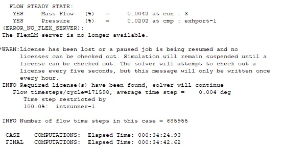
YES Mass Flow (%) = 0.0042 at con : 3
YES Pressure (%) = 0.0202 at cmp : exhport-1
Flow timesteps/cycle=171598, average time step = 0.004 deg
Time step restricted by
100.0%: intrunner-1
INFO Number of flow time steps in this case = 685955
CASE COMPUTATIONS: Elapsed Time: 000:34:24.93
FINAL COMPUTATIONS: Elapsed Time: 000:34:42.62
From above simulation we clear that -
- Maximum descretization length require less simulation time and vice versa.
- For maximum discretization, flow step is minimum and vise versa.
- For maximum descretization, timestep is minimum and vice versa.
GEOMETRY :-
1. Engine geometry :-
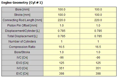
Here given the geometry of engine like bore, stroke, connecting rod etc.
Bore = 100mm Stroke = 100mm Connecting rod length = 220mm
Bore and stroke have same length means the engine speed is minimum.
2. Engine operating conditions :-
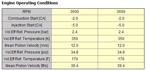
Both case have same speed so that everything is same value here.
3. Engine performane predictions :-
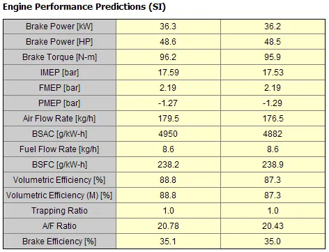
For Case-1
Brake power = 48.6 HP Brake torque = 96.2Nm
Air flow rate = 179.5 Kg/h BSAC = 4950 g/KW-h
BSFC = 238.2 g/KW-h Brake efficiency = 35.1 %.
For case-2
Brake power = 48.5 HP Brake torque = 95.9 Nm
Air flow rate = 176.5 Kg/h BSAC = 4882 g/KW-h
BSFC = 238.9 g/KW-h Brake efficiency = 35.0 %.
4. Engine performance- Fuel energy basis :-
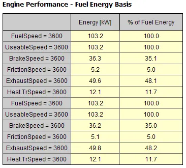
Different speeds are given here.
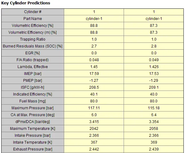
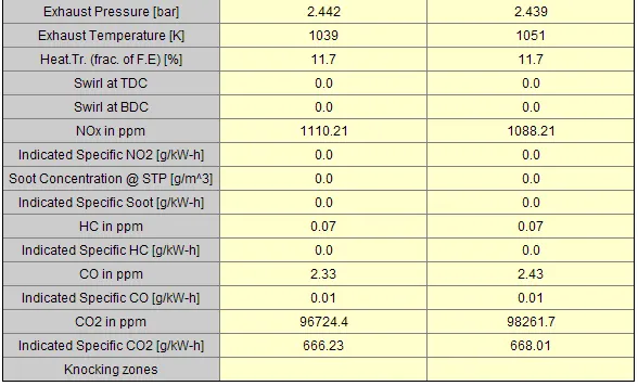
5. Key cylinder predictions :-
For case-1
ISFC = 208.5 g/KW-h Maximum pressure = 117.11bar
Maximum temperature = 2042k NOx = 1110.21 ppm
CO = 2.33 ppm CO2 = 96724.4 ppm
For case-2
ISFC = 209.1 g/KW-h Maximum pressure = 115.18 bar
Maximum temperature = 2058k NOx = 1088.21 ppm
CO = 2.43 ppm CO2 = 98261.7 ppm
6. Engine MEP, Trque & Power :-
MEP = 17.6 bar Torque = 109.9 Nm Power = 41.4 KW
PLOTS :-
1. Pressure plots :-
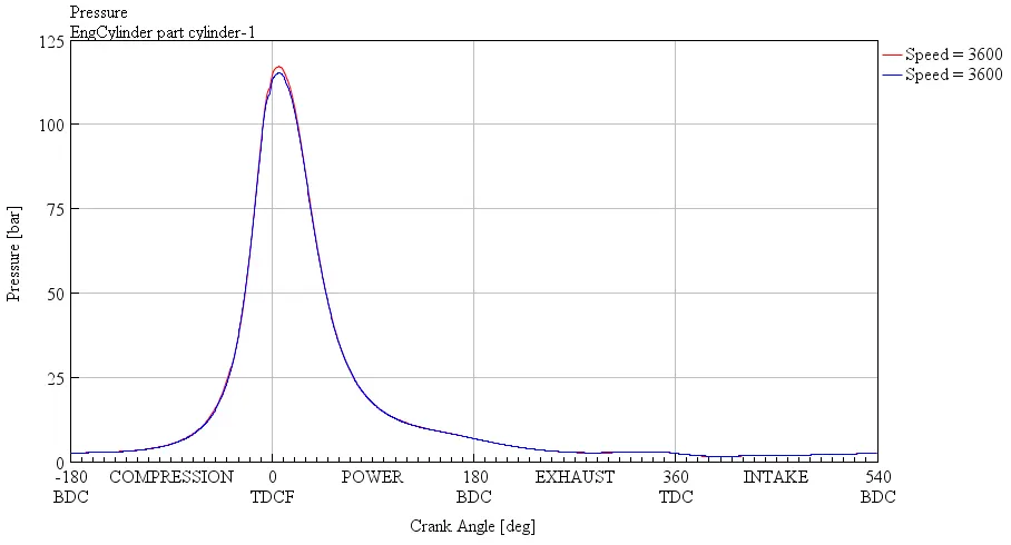
For both the case have same pressure it means that pressure is depends upon engine speed only and not on discretization lengths.
2. Burned fuel plots :-
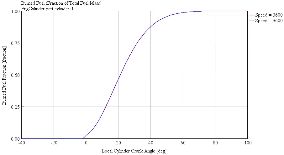
This is also depends on the engine speed and not on discretization lengths. Burning rate increases at combustion stroke I.e. power stroke.
3. Mass flow rate plot :-
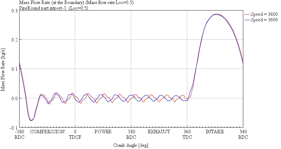
Its also depends on engine speed and not on discretization lengths. It increases at Intake stroke.
4. Static pressure plot :-
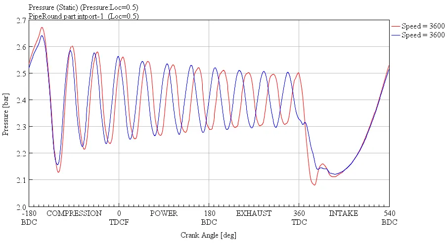
It kept constant for same engine speed but at intake stroke it decreases as shown in above plots.
5. Temperature plot :-
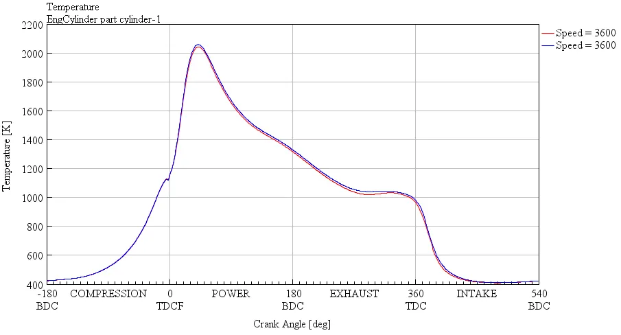
Teperature is depends upon engine speed and not on discretization lengths. Thats why temperature is same for both the casses. It is maximum at power stroke and minimum at intake stroke as shown in above plots.
CONCLUSIONS :-
From above project we can clear that following points-
Simulation for Case-1
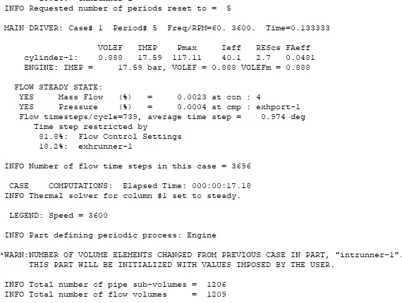
Simulation for Case-2
- GEM3D is the powerful tool by which we can converted 3D model to 1D model by using discretization methods.
- While converting parts numbering for inlet and outlet given in propar way.
- For discretization we need to convert our full model into small small parts.
- Before exporting into GT power orientation of geometry is take propar for simplicity in GT power connection linkage.
- Due to change in discretization length our simulation results varries but not other plot or geometry influences.
- Pressure plot, Burned fuel plots, mass flow rate plot, static pressure plot and temperature plots not depends upon discretization lengths as shown in figure. Because for both the cases have same plot we get.
So, in this way I building intake manifold from STL model with the help of GEM3D. Explore the 1cyl DI model for changing discretization lengths and find out the parameters like Torque, BSFC, maximum cylinder pressure, Simulation time …etc.