Assignment 11
Challange-1:
Running the single-cylinder Direct-Injection Diesel engine with two different discretization length of 40mm & 0.1 mm for intake runner to compare the results.
Discretization: It means dividing the domain into small sub-volumes of Approximate lengths to solve the quantities like Pressure, Temperature, Mass-fraction, etc. The discretization length affects the time step when we are using Explicit solver, In implicit solver, the time step is user imposed and thus discretization length will not affect the time step but does affect the number of pressures, temperatures, etc. to be calculated.
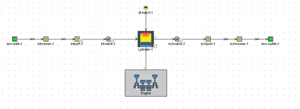
Engine details: For this simulation, we are using a single-cylinder Direct Injection Diesel engine with varying discretization lengths in the Intake runner.
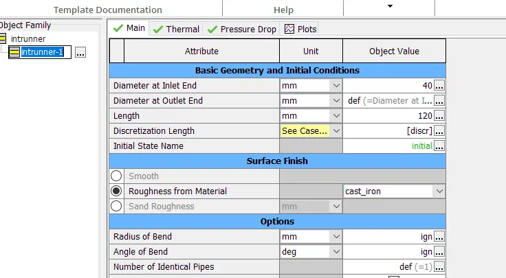
In the Intake runner templet, the Discretization length parameter is imposed as a user-defined input parameter.
The case set up for the simulation is.
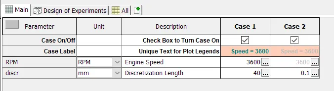
In both cases, the only parameter that varied is the discretization length.
Results:

The above-shown table represents simulation speed, if we decrease the discretization length the number of solution zones increases this will eventually increase the simulation time.
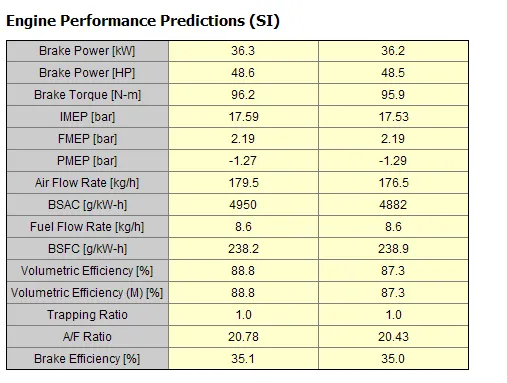
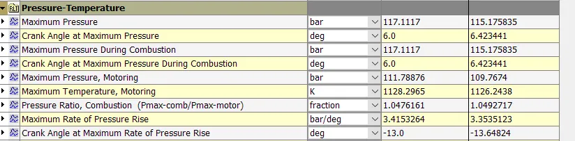
The above-shown table represents the comparison of Engine performance & In-cylinder pressure for both cases, On comparison results, the small deviation in the results is observed, Case-2 results are more accurate. There is a trade-off between the accuracy and simulation speed so the discretization length should be carefully selected.
Challenge-2:
Building intake manifold from the STL model.
The tool we are using is GEM3D it is a graphical 3D tool used to build and discretize flow systems for use with GT-SUITE. It provides the ability to build models using component templates, import shapes from an STL file, connect complete flow systems, dimension the model, and automatically discretize. The resulting discretized model from GEM3D is compatible with GT-SUITE and can be opened directly using GT-ISE.
Building Process:
After launching the GEM3D, create a new file and import the Intake manifold STL model from the Tutorials.
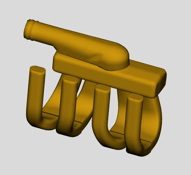
Step-1: The above-shown model should be separated for discretization for this, we will use the Separate By Curves operation. This will separate the geometry into parts based on changes in the surface of the object. This process will also separate the intake runners into two different sections near the area change at the top of the runners. For flowing the fluid within the manifold the caps are deleted.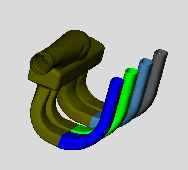
Step-2: For further discretization, the pipes from the runner should be separated for this we are using a 3-point cutting plane tool is used. Since we want to cut off the runners, let's pick 3 points on the underside of the manifold block to separate the intake runner from the pipes.
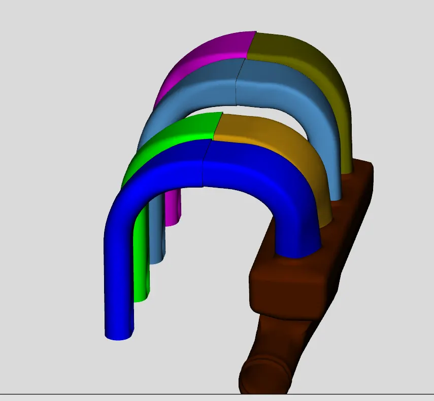
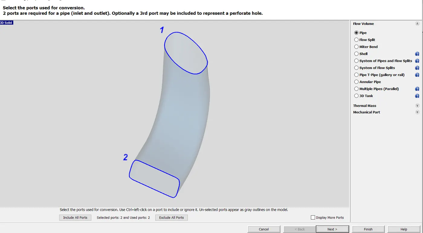
Step-3: To reduce the complexity in the design by converting multiple bends pipes into the smooth transition into the runner by specifying the inlet and outlet diameters. This is done by selecting the Convert shape into a component. The numbering defines the flow direction from 1 to 2 direction and we can specify diameters at inlet and outlet sections. The intial state of the component is defined by imposing the pressure as 1 bar and the Temperature as 300 K. The air composition is selected as a combustion air templet. In the Thermal tab and type in 300 K for the Imposed Wall Temperature and the conversion is complete. This is implemented for all the pipes runners.
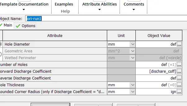
STEP-4: For defining the flow orifice connection is added by defining the number at the inlet and outlet openings. This is done for every pipe in the intake manifold. The forward discharge coefficient of 0.95 is added to the case setup file.
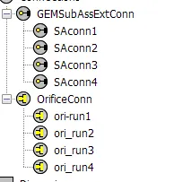
These are the connection that is defined for defining the flow.
STEP-5: Now that we have the runners converted, let's move to the other end of the manifold. The entrance appears to consist of a pipe section with a round and D-shape, then a 90 degree turn into the manifold. The straight section can be converted into 2 pipes, one representing each effective diameter. Therefore we need to cut and separate these two sections so they can be converted. Since they are pipe sections, we can utilize the pipe normal cutting plane operation. From the Cutting Planes group in the Convert tab, choose Pipe Normal Cutting Plane. To place the cutting plane, click on the rounded outer wall of the model very close to the entrance. This will place the pipe normal cutting plane at that location and in an orientation that is normal to the flow direction, as shown in the image below, as well as open the pipe normal plane window.
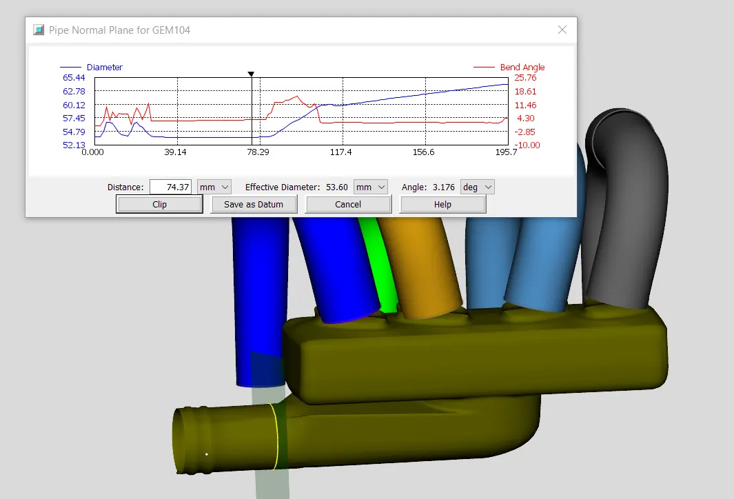
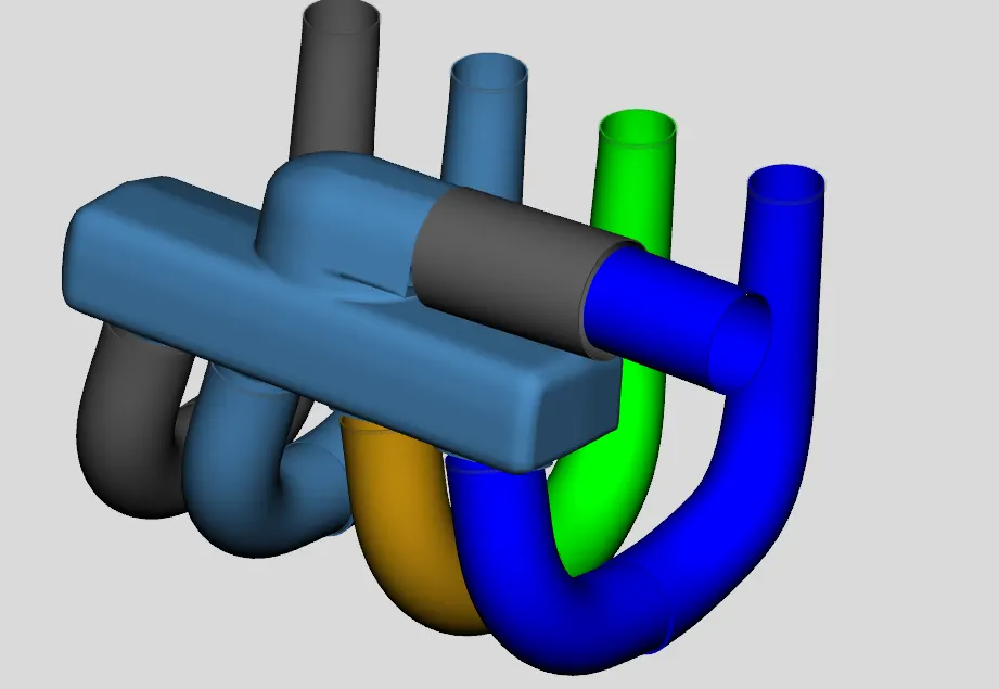
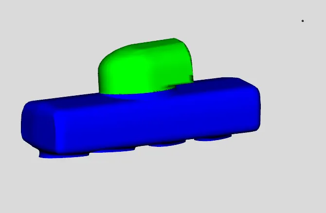
The above figures are the step by step process for converting the inlet pipe into three different sub-volumes and all these are converted into pipes by using Convert Shape into Component tool. The connections are made for defining the flow in these pipes.
STEP-6: In our case, each end of the manifold has a runner connection. Since the center inlet is wide enough to cover both middle runners, the center section of the manifold should cover both middle runners. That means we want to divide the entire manifold into 3 sections; a center section and 2 end sections. The first step is to use a cutting plane to cut off the first end section toward the first runner. Enable the cutting plane by selecting 3 Points Cutting Plane from the Cutting Planes group in the Convert tab. Select 3 points on the end of the manifold such that they form a plane nearly perpendicular to the manifold section. Use the 3 black crosshairs in the image below as a guide. Once the 3 points are selected, the cutting plane is added as seen in the image below, and the cutting plane control window is opened. Once the plane is formed, we need to translate it along the manifold so that it is between the 1st and 2nd runners where we want to make our cut. After this restore the cutting plane and adjust the plane in between the 3rd and 4th runner where we want to make our cut.
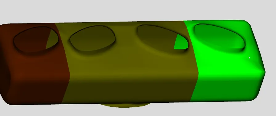
STEP-7: These manifolds are split into three regions and they were converted into flow-splits using Convert Shape to Component and numbering of these are carefully selected according to the direction of the flow.
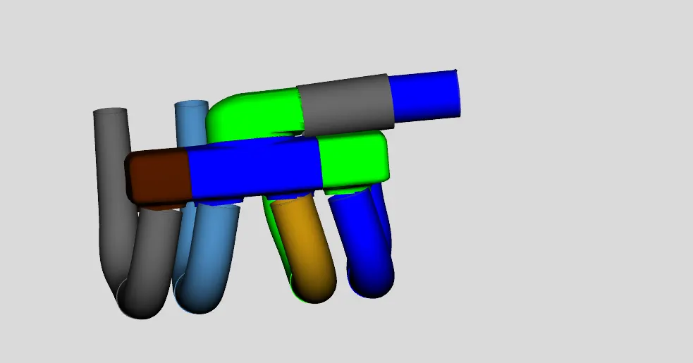
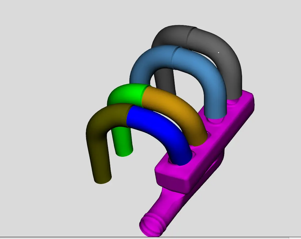
STEP-7: You will notice that during the process of converting meshes to components, we created several pipes that do not align perfectly. To remedy this, we can use the Flow connection operation to join the runner sections at the top of the manifold. This will show available surfaces for adding flow connections, as shown below. To join the runners together, click on the flow connection face at the end of the first intake runner, then click on the flow connection face at the end of the second intake runner. The sections should join together, as shown in the screenshot below. Join the other three runners together as well to form the manifold as shown in the screenshot below. You will notice that some of the runners are positioned slightly differently than before. This is acceptable, as the geometry of the flow volumes has still been maintained.
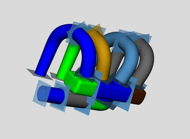
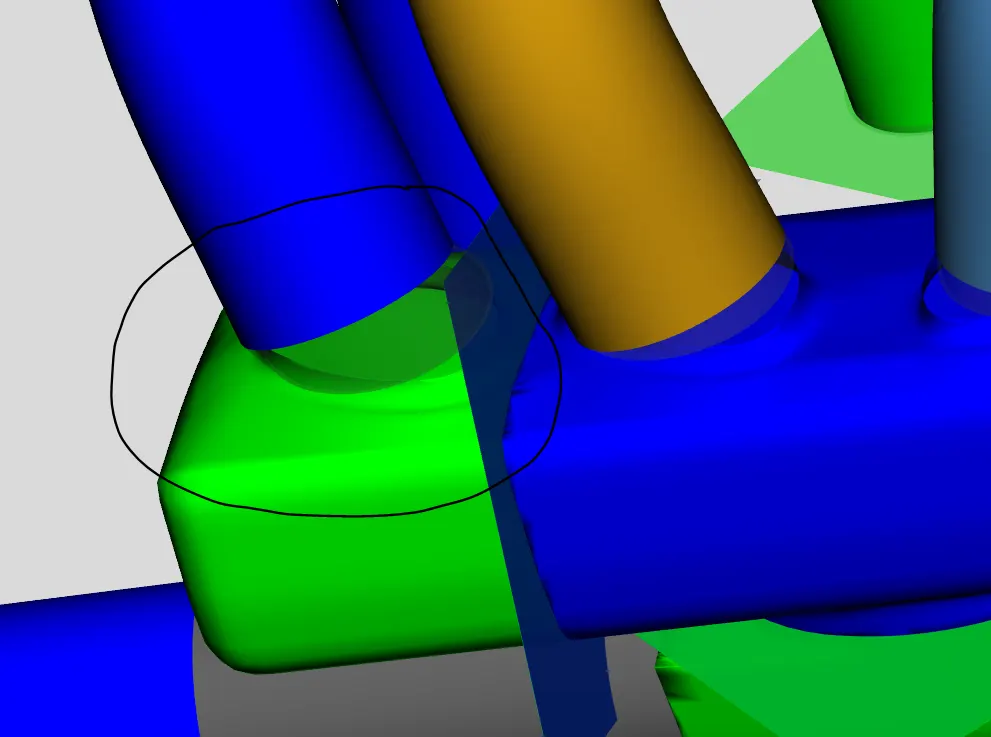
STEP-8: While converting the multi bend pipe to uniform pipe we lost the smoothness in the flow this leads to unexpected errors to overcome this error we should use an Extruded connection this makes the smooth connection between manifold and pipes.
STEP-9: Now we should save the model and use the Export GT Model option to convert the 3D model into GT 2D map model and mention the Discretization length should be 40mm. The 3D model should be oriented in the correct position to get a clear 2D model.
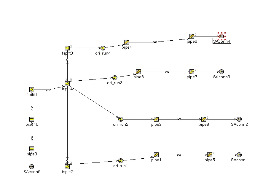
This is the step by step procedure to convert STL intake manifold runner into GT 2D model.