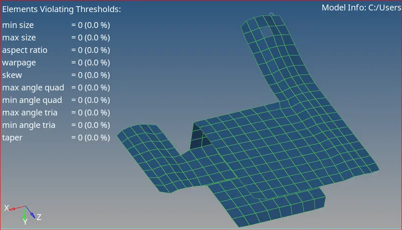
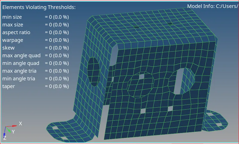
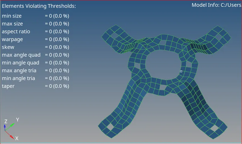
Assignment 1-2D Meshing Challenge
Assignment 1- Crashworthiness
2D Meshing Challenge
OBJECTIVE:
- Import all the CAD files
- Clean up the geometry until no topological error is found
- Extract Mid-Surface for the geometry
- Meshing according to given quality criteria
- Improving mesh flow without any quality issues
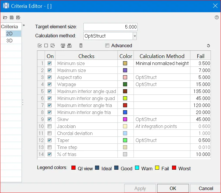
Quality Criteria Used:
PROCEDURE:
1. Import Geometry: Go to File >> Import >> Model/Geometry

Imported CAD geometry
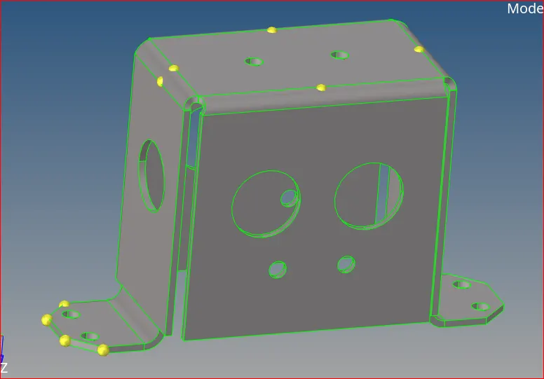
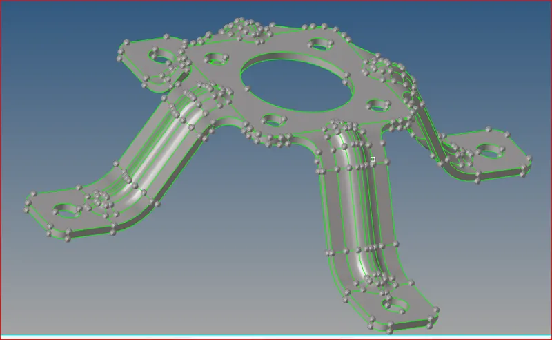
Imported CAD geometry Imported CAD geometry
2. Removing Duplicate Surfaces
- The goal of topology clean-up is to restore the surface data to a perfectly clean representation of the part.
- Sometimes we can visually detect duplicates, there will be a glitch on the surface indicating that it is a duplicate surface.
- We can also check for duplicate from the defeature panel.
- Go to geometry >> defeature >> Duplicates >> Surfaces (Displayed) >> Clean-up Tol = 0.01 (Default) > Find > Delete
- Follow this procedure for all models
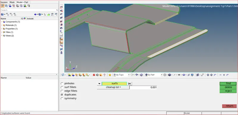
Finding duplicate Surfaces
3. Geometry Clean-up
- Use Geometry >> Quick edit >> Toggle option to remove all the free edges
- Use Geometry >> Surfaces >> Ruled option to create New surfaces
- we can also create lines and trim the surfaces with the lines using Geometry >> Surface edit >> Trim with lines option
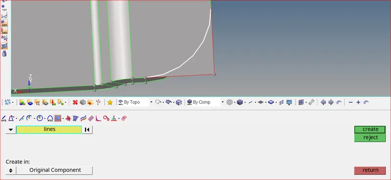
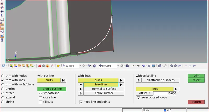
Creating lines using extract edge Trimming surfaces with lines
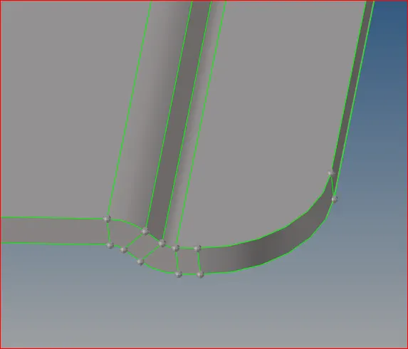
Deleted extra surface after trimming
4. Removing circles below 5mm diameter
- Check the diameter using the Measure(F4) option.
- Remove the small circles using quick edit >> Filler surface and then toggle the edges as shown below
- follow this procedure for all models
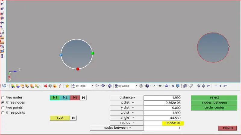
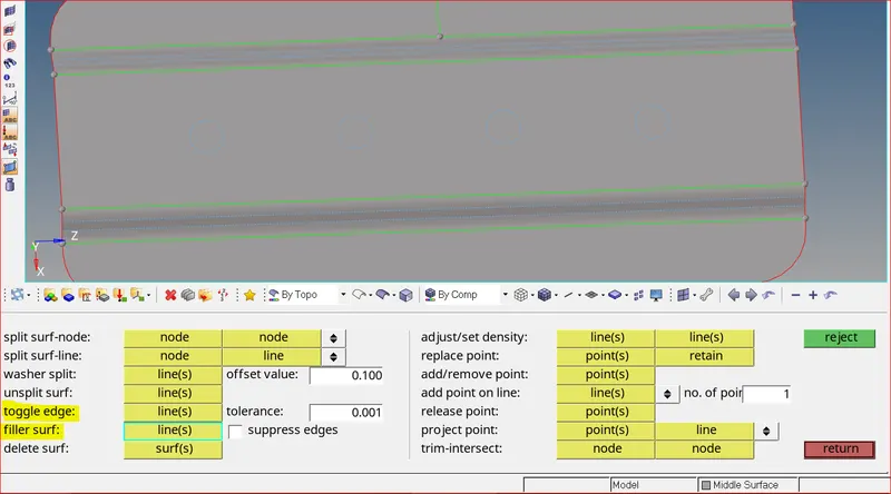
Measuring circle Circles filled and toggled
5. Visualization
- Scan the entire geometry
- Under visualization options we can see there are four types of edges which are 1) Red colour for free edge 2) Green for shared edge 3) Blue for supressed edge 4) Yellow for non-manifold(t-joints).
- We can also adjust the level of solid transparency in the visualization options.
- Topology repair consists of correcting connectivity errors between adjacent surfaces. The errors include unconnected adjacent surfaces, duplicate surfaces, missing surfaces
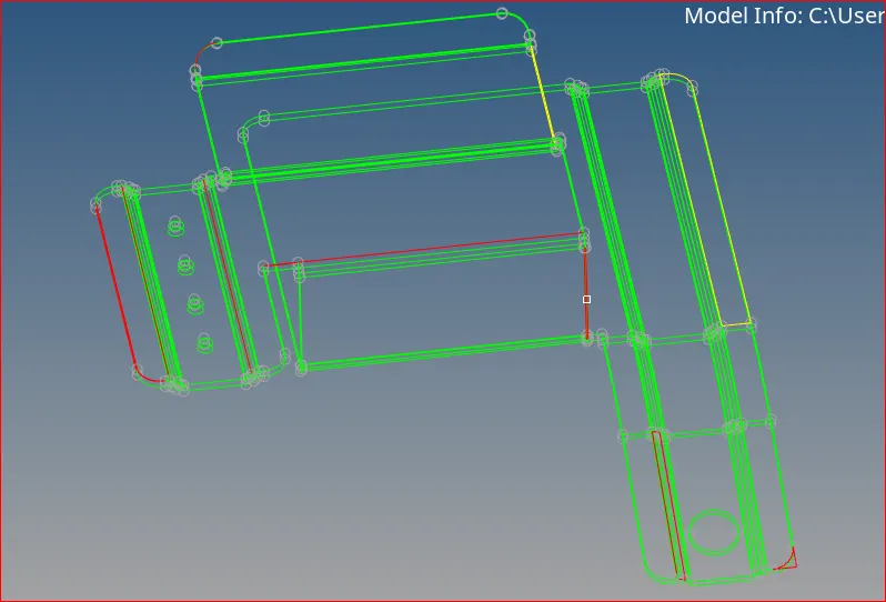
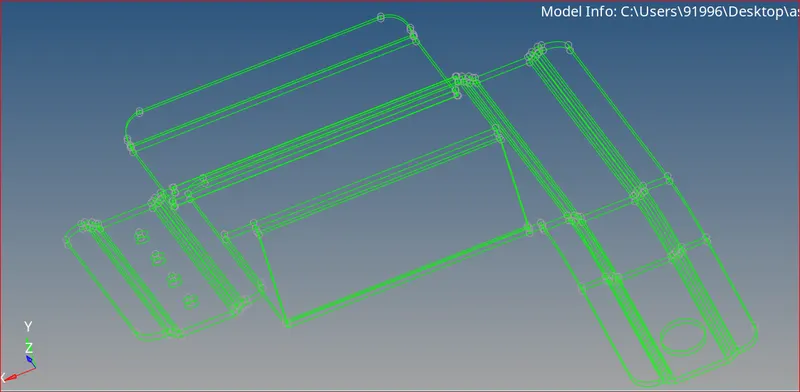
Before Geometry Clean up After Geometry Clean up
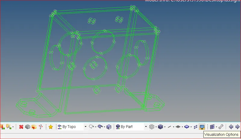
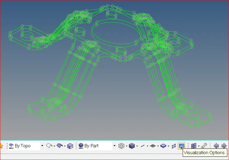
Visualization in Wireframe mode
- There are no free edges and geometry. Therefore, we can create mid-surfaces now.
6. Auto-Mid surface generation
- Go to Geometry >> Midsurface >> Auto mid surface option
- Select the required extraction options and select all the surfaces and click on extract
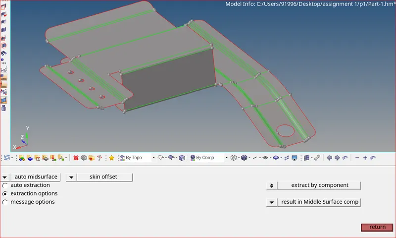
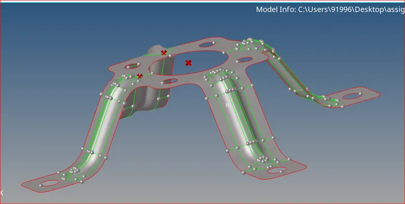
Auto Mid surface generated
7. Mid Surface Using Offset
- Measure the thickness of the parent geometry and offset one side of surfaces into the middle by using Surface edit >> Offset option
- Create a component as mid surface and duplicate all the off-setted surfaces into that component
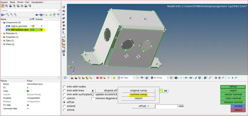
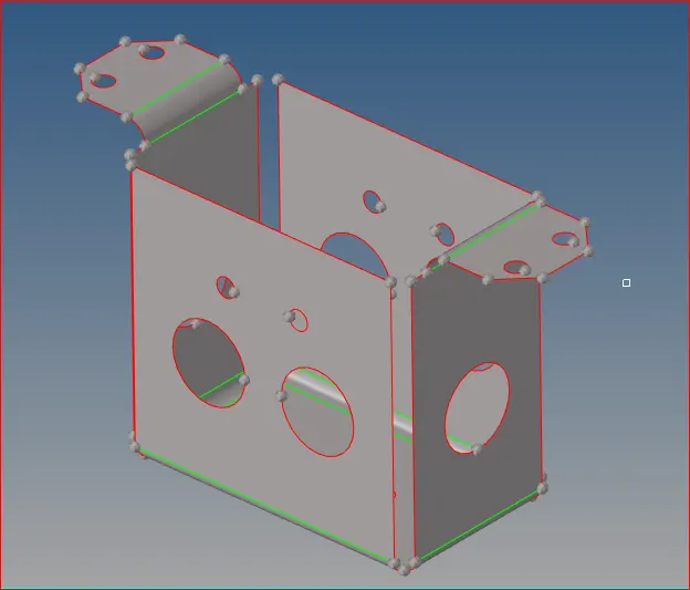
Off-setting surfaces Mid surface
8. MESHING
- Now mesh each surface separately to achieve better mesh.
- 1st we need to input quality parameters. Go to >> Preferences >> Criteria file settings and enter the values or import criteria file.
- I have used the 'Mixed’ option to generate the mesh for this challenge because we are preparing the model for crash & safety simulations. The quad-only mesh is preferred for durability and structural simulations.
- We can also divide the regions manually to achieve better mesh flow. Trias will be there in some areas, but they should be in the direction of mesh flow.
- Therefore, I have divided the regions in a way that the mesh flow will be good. Usually, this is done while doing geometry clean up on the mid surface
9. Rotating circles parallel to Edges for better mesh flow
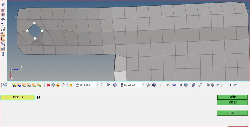
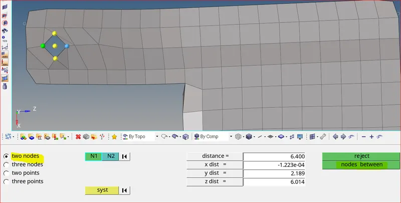
Creating temp nodes Creating node in the middle
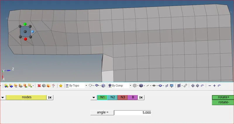
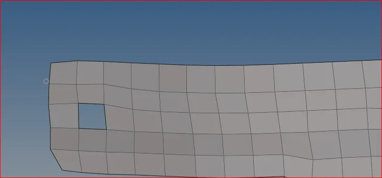
Rotating temp nodes Better mesh flow as a result of rotating
10. Positioning Mesh
- We can easily position the elements from one place to another using tools >> Position >> Elements option
- Select the elements and nodes as required and position as shown below
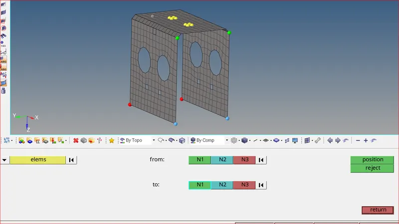
Position of elements is successful
11. Equivalence
- After meshing the whole geometry. Use tools >> edges option to check whether there are any free edges in-between the elements.
- clear all the free edges using equivalence.
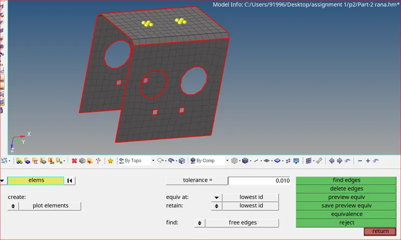
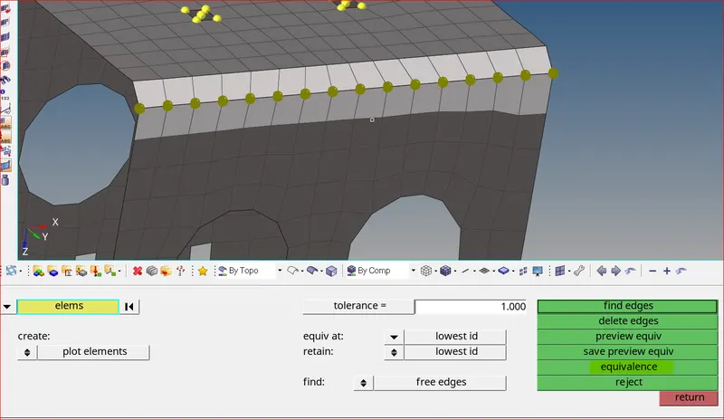
Finding edges Clearing edges using equivalence
12. Rotating Mesh
- The mounting bracket model is symmetric. Therefore we can either reflect or rotate elements to save time
- We can also rotate the elements using the required angles as shown below
- Make sure you duplicate elements before rotating
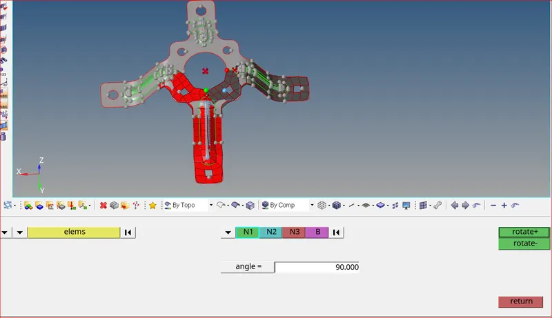
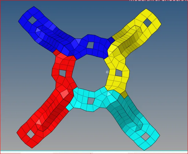
Rotating elements Elements rotated successfully
13. Organize
- Using tools >> organize option we can move surfaces, elements, etc. from one component to another easily.
- Make sure you check the destination component before organizing
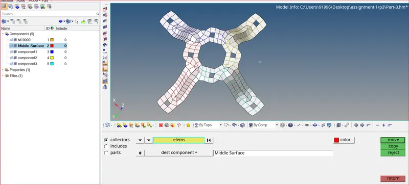
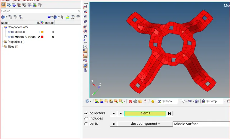
Organizing elements All elements are organized to middle surface component
14. Clean Up tools for clearing off elements and to achieve better mesh flow
- Use 2D >> Quality index tool >> Clean up tools (Smooth, drag tria elements, Element optimize, combine tria element, Split quad element, Place node) to eliminate all off elements.
- Smooth: This option helps us to achieve better mesh flow. After clearing off elements, we usually use smooth in that area.
- Drag Tria Element: we can drag any tria element out of the geometry easily. This option helps us to remove trias easily
- Split Quad Element: Splits one quad into two trias. We use this to reduce rotating quads
- Combine Tria Elements: Combines two tria elements into one Quad element. Helps in Reducing tria percentage
- Element Optimize: Smooths the quality by adjusting the neighboring elements. Helps in Clearing elements for quality
- Place Node: This option allows us to manually change the position of a single node. Helps us to clear off elements
15. Assigning Thickness
- according to the thickness of the component and then assign that property to the component
- Different thickness should have different properties and components as well
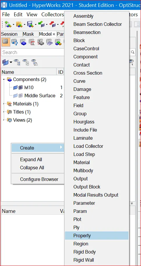
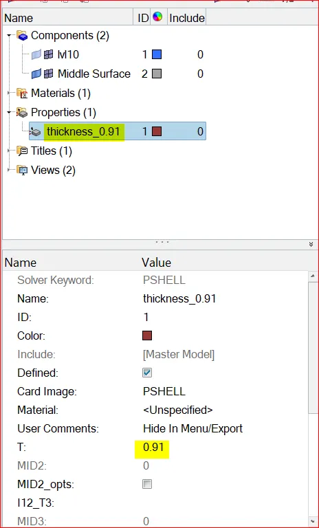
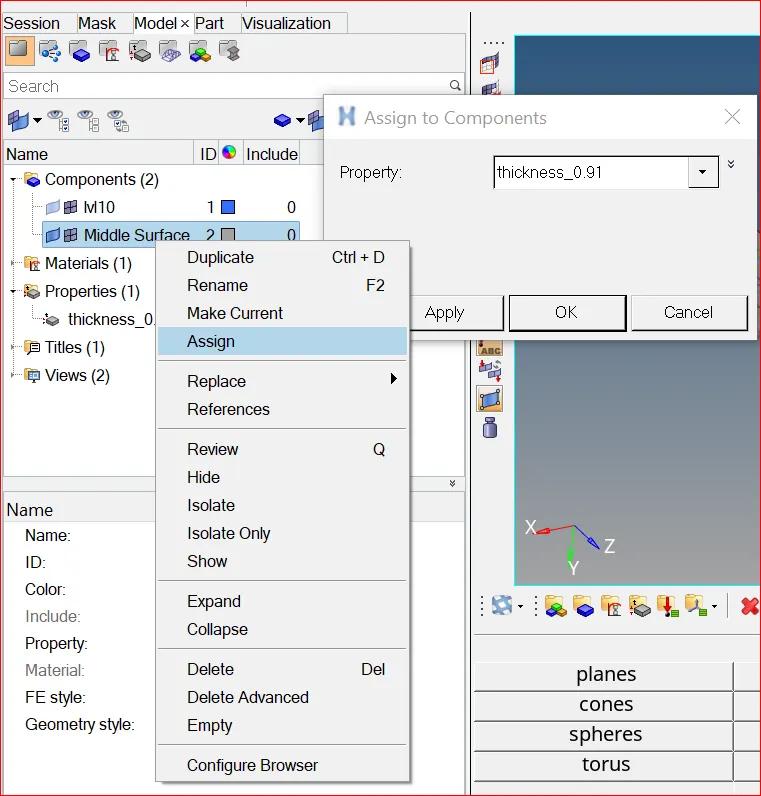
Creating Property Assigning thickness to property Assigning thickness to component
16. Transparency
- In this mode, we can compare our mesh with the parent geometry.
- we can also check the thickness using 2D detailed representation option.
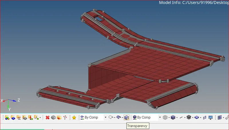
Checking elements in transparency mode
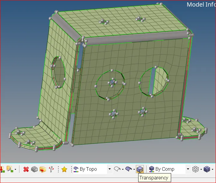
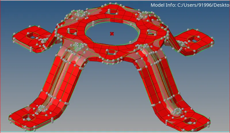
Checking elements in transparency mode
Conclusion:
After completion, there are no quality issues found in this rear door model. Mesh flow is good.