Assignment 1-2D Meshing Challenge
#10 // Assignment 1_ 2D Meshing Challenge.
Aim: To Mesh the given components by giving the target Element size as "5 units", as per given Quality criteria and assigning the thickness to the FE.
OBJECTIVE:
- Geometry clean-up.
- Extract Mid-Surface.
- Meshing as per given Quality Criteria.
- Assign Thickness.
Given Quality Criteria,
Target Element Length : 5 Units
Minimum Length : 3.5 Units
Maximum Length : 7 Units
PROCEDURE:
MODEL_1 (Practice) ->
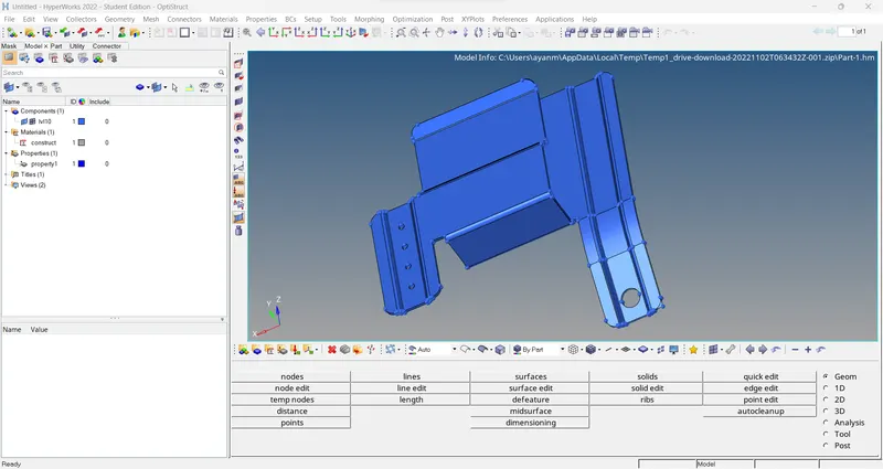
1) Import the model into Hypermesh. -
The given model is imported into Hypermesh using the import option on the menu bar.
2) Geometry Clean-up -
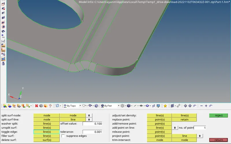
Before extracting the mid surface from the model, ensure that the model surface is perfect and free from errors like free edges, duplicate surfaces, and missing surfaces. If any defects are found then the required geometry clean-up needs to be done using the various tools such as toggle edge, filler surf, replace points, etc. available under the quick edit panel. [F11 (or) Geom > quick edit]

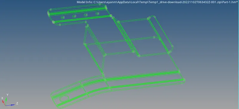
> Geometrical errors in component, We can analysis in topo mode or wired frame mode..
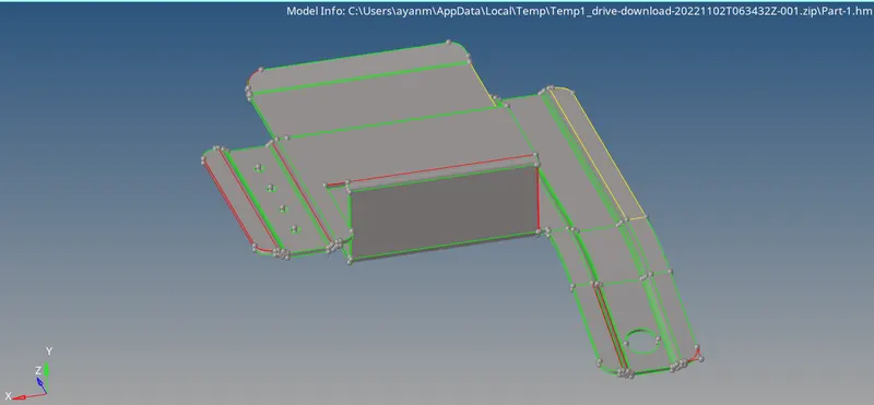
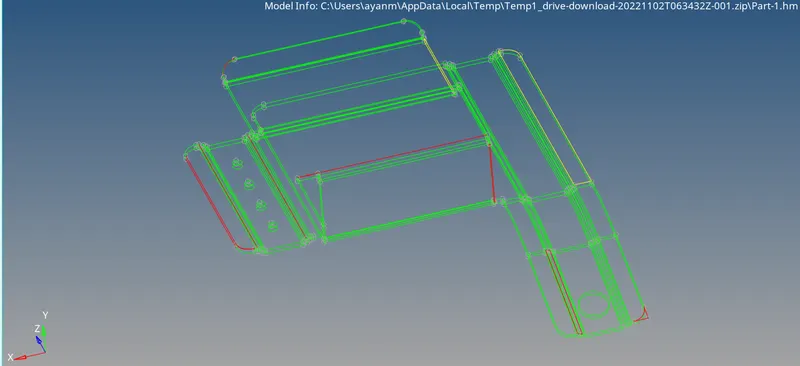
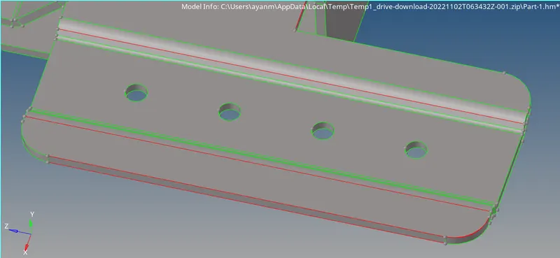
On the model, if any lines are too close to each other or if the distance between the lines is less than the minimum element length, then one of the lines needs to be suppressed using the toggle edge option. Otherwise, on meshing, elements that fail the minimum element length criteria will be created between the closely spaced lines. Also, toggle edge is used to close the gap between two surfaces free edges.
> For free edge.... used quick edit > Toggle.
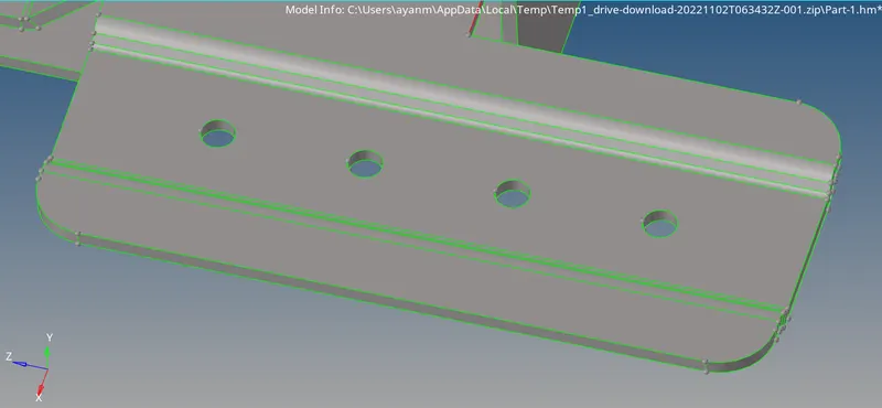
> For gaps on surface.... used quick edit > replace points. (if gaps is small).
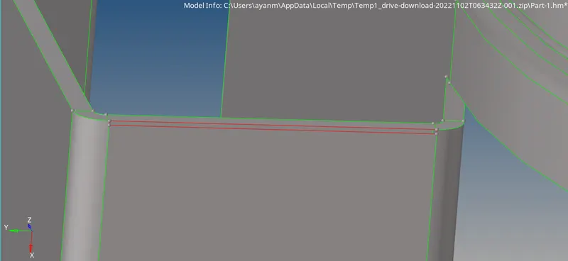
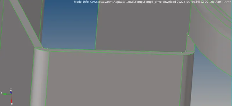
> For duplicate surface.... used quick edit > delete surf.
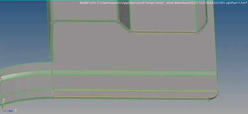
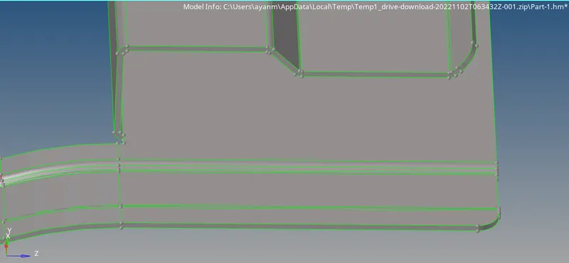
> For missing surfaces.... used quick edit > filler surf.
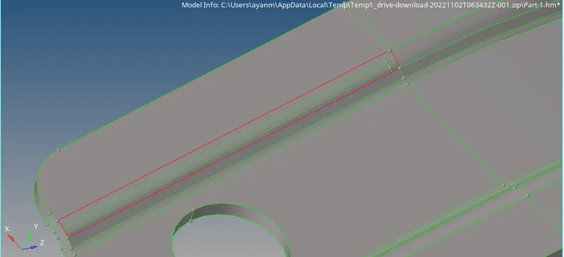
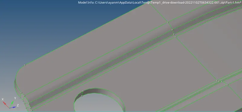
> For unwanted extra surface.... used Geom > surface edit > trim with surf to surf, then delete extra surf by F2.
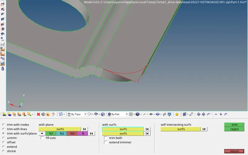
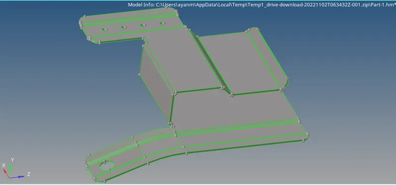
> After Geometry error fixed..
3) Mid surface extraction. -
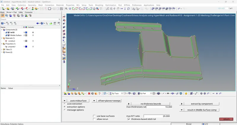
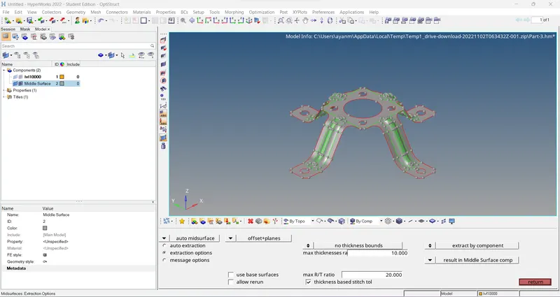
Since the given component is made of sheet metal and is of uniform thickness throughout, the midsurface is extracted through automidsurface tool. (Geom > midsurface > select surfs > extract).
[Note: here we go for offset + planes + sweeps in extraction option.]
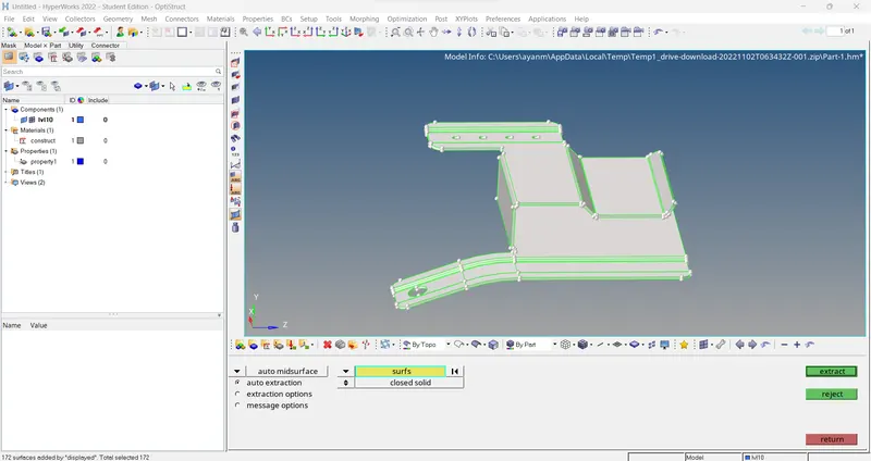
> Extracted midsurface..
4) Mid surface clean-up -
After extracting the midsurface any defects on the extracted midsurface are rectified before starting the process of meshing. Also, for ensuring proper mesh flow and also for ease of meshing the surface is divided into sections and the meshing is carried out on each of the sections one by one.
> First measuring hole diameter.. used Geom > distance > Three nodes.
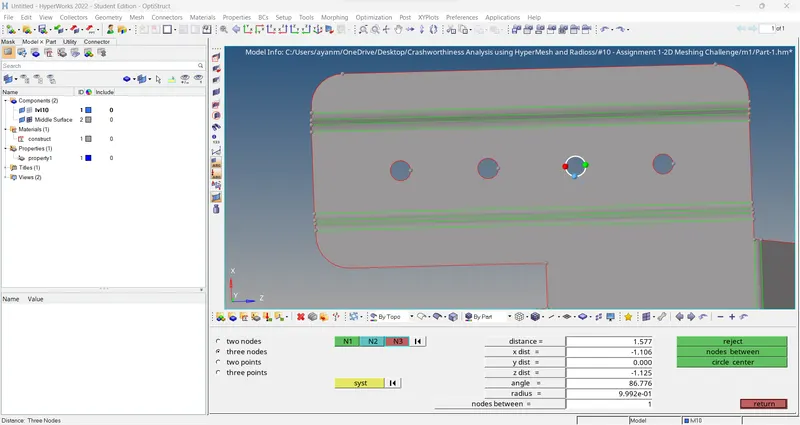
> Since the hole dia. is less than 5 mm, they need to be removed before meshing.
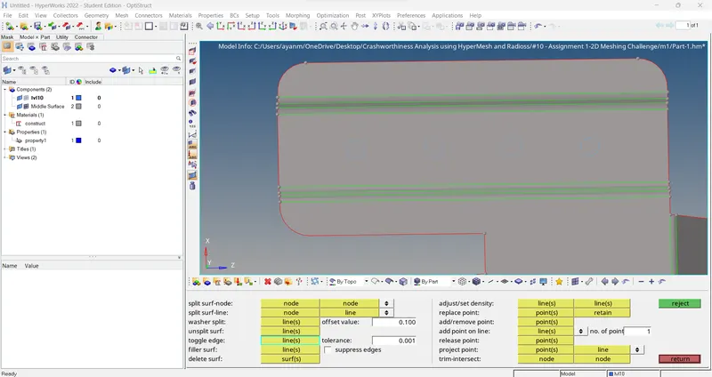
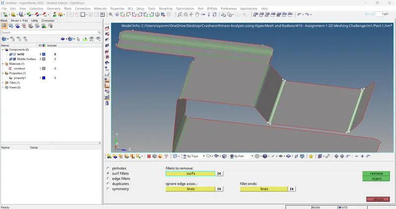
> The surface fillets having a radius less than the minimum element length of 3.5 mm need to be defeatured in order to prevent the elements from failing the minimum length criteria.
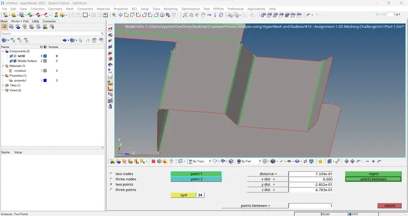
> Defeaturing surface fillets.. used Geom > defeature > surf fillets > removed.
> After midsurface geometry cleanup..
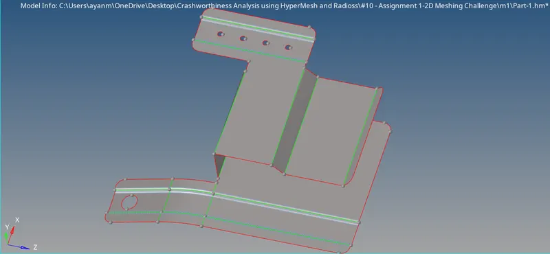
5) Meshing of midsurface
The given quality criteria’s need to be specified using the criteria file editor before meshing the model. (This Quality same for all three models.)
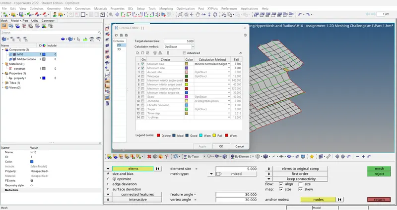
> Once the quality criterias are set, automeshing is performed with a target element size of 5 mm.
> Go to 2D > automesh (F12).
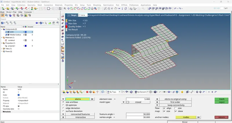
> Ensuring proper mesh flow and quality of elements generated..
The generated mesh is examined properly to ensure that there is a proper mesh flow. Also, the number of trias should be kept to a minimum. Ensure that there are no rotating quads, back-to-back trias, opposite trias or trias on the feature line.
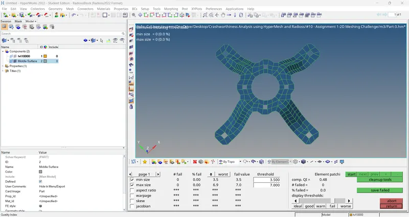
Check if any elements are failing for any of the given quality criteria’s. If any element is found to be failing the given quality criteria, then the clean-up tools are used to correct them.
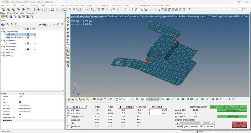
> Only two elements are found to be failing the quality criteria. But it is kept as it is since it affects the feature capturing.
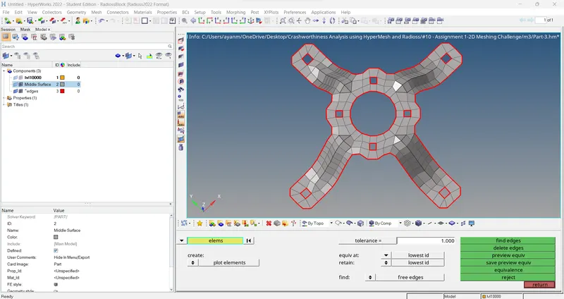
6) Checking for free edges.
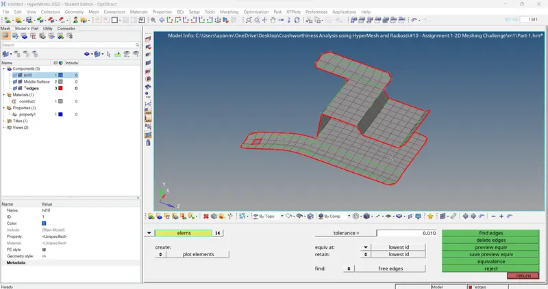
7) Check Normals.
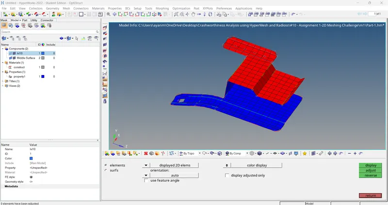
9) Assigning thickness -
After meshing, the elements have to be assigned the measured thickness of the component. For this, a ‘property’ has to be created (Right-click tab area > create > property).
> Measuring thickness of parent component.
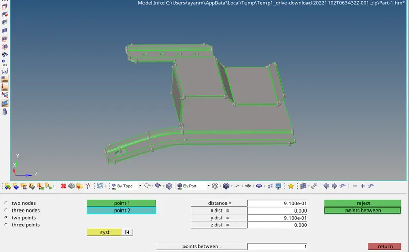
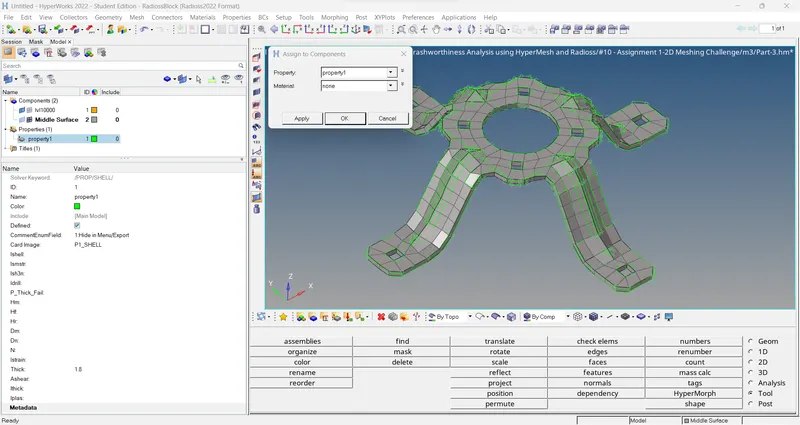
> Under the property menu, the thickness ‘T’ has to be specified. To assign the property to the component, right-click on the corresponding component and choose the ‘assign’ option. In the pop-up menu select the corresponding property from the drop-down list and apply.
> Assigning Thickness.
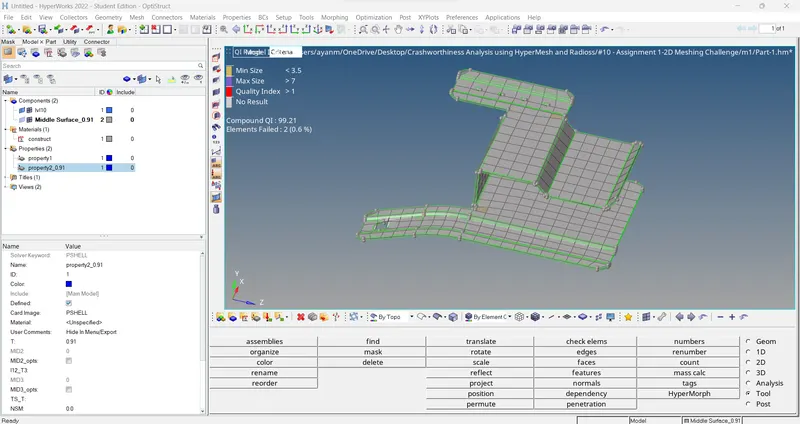
> FINAL MODEL VIEW....
> Without thickness FE..
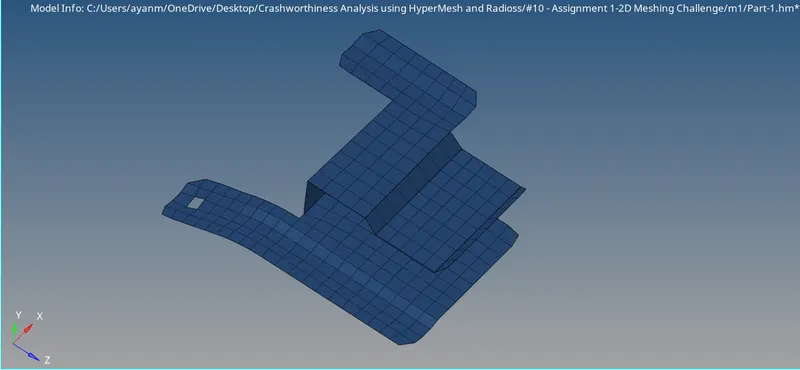
> With thickness FE..(2D Detailed Element Representation) -
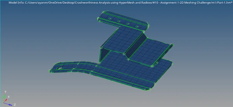
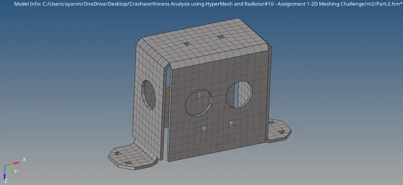
MODEL _ 2 (Clip Repair) ->
All the steps carried out for Model_1 are also repeated for Model_2.
1) Import the model into Hypermesh. -
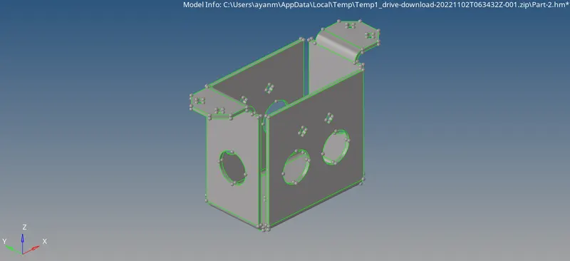
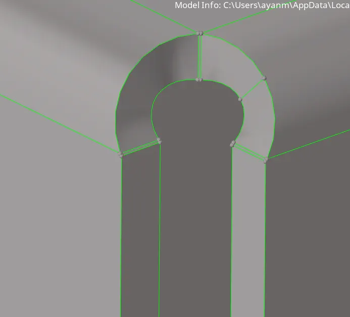
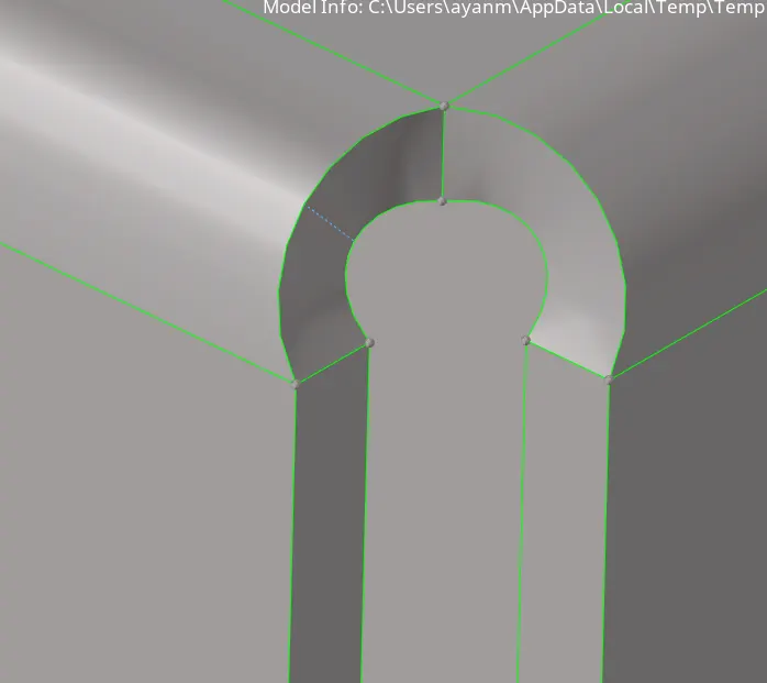
2) Geometry Clean-up -
> used quick edit > replace point.
3) Mid surface extraction -
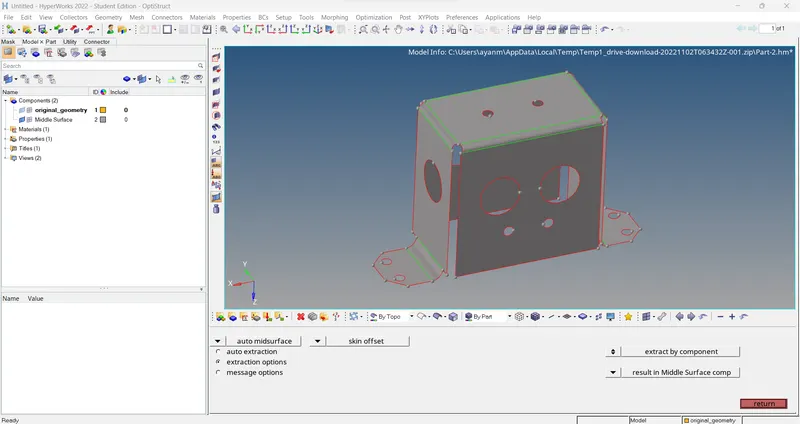
> For model2 go to Geom > midsurface > extraction option (skin offset) > auto midsurface > extract.
4) Meshing of midsurface -
Since the model is symmetrical, meshing can be performed on one half of the model and the elements can be reflected onto the other half.
> First create node in middle & then trim the surface with planes.
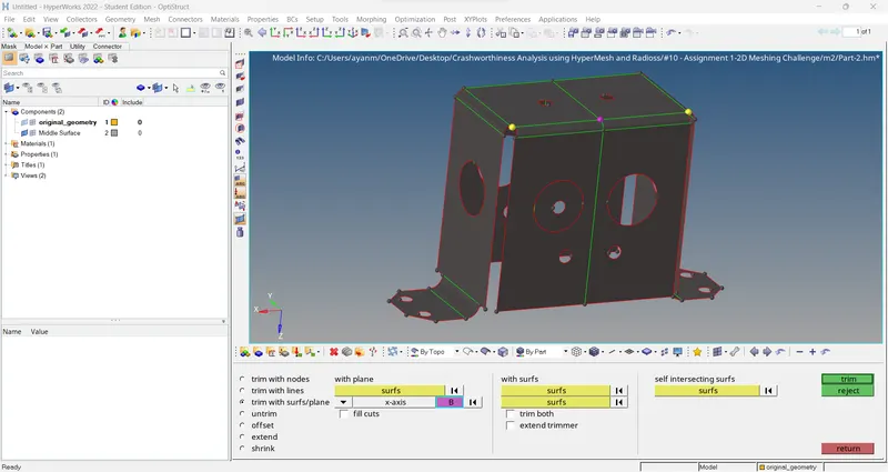
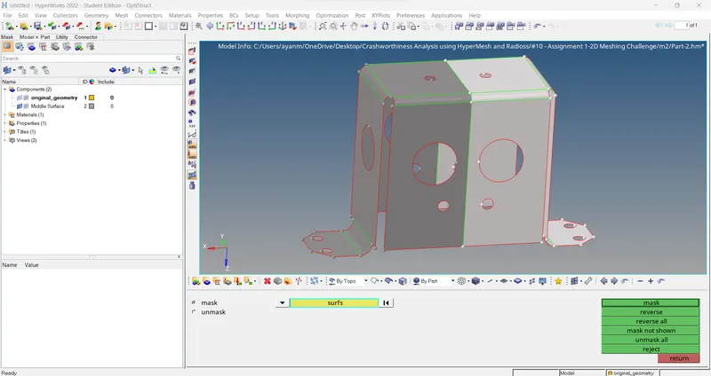
> Mask half surface..
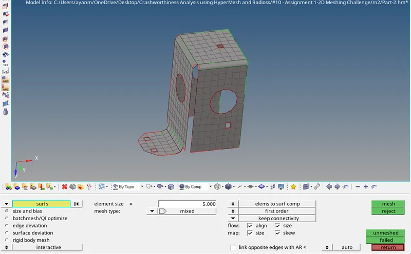
> After mesh..
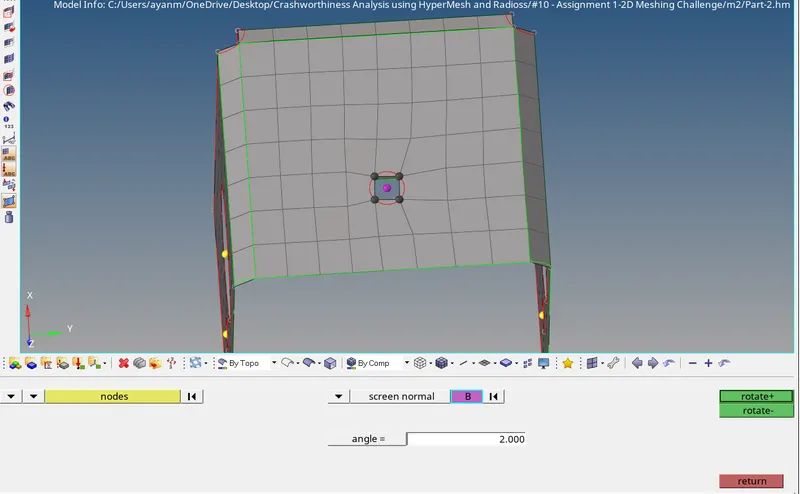
> Rotate nodes in hole region....used Tool > rotate.
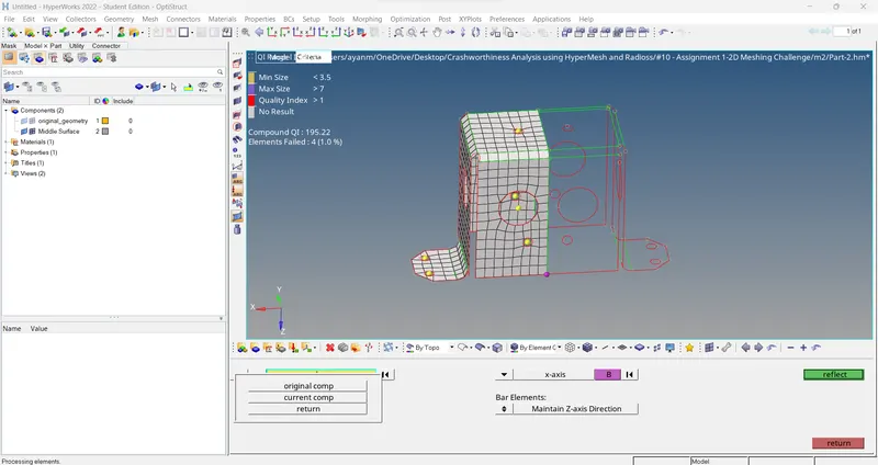
> Reflect Mesh in other side..used Tool > reflect.
> Equivalance..used Tool > edge (Shift + F3) > preview equivalance(set tolerance) > equivalance.
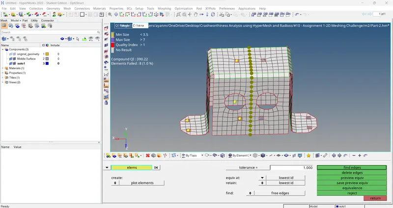
> Checking node connectivity..
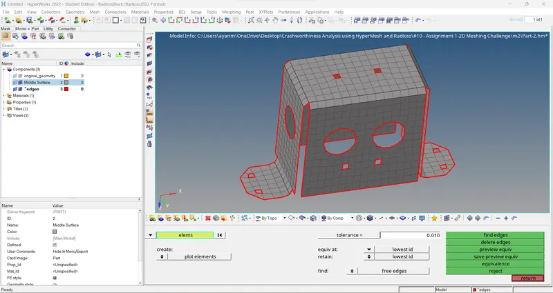
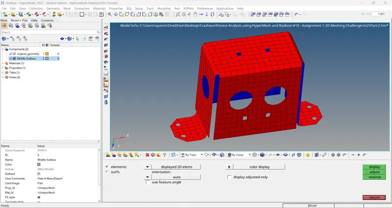
> check normals..
5) Ensuring quality of elements generated -
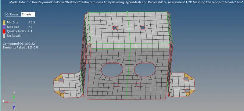
> Some elements are found to be failing the quality criteria. But it is kept as it is since it affects the feature capturing.
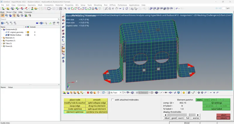
6) Assigning thickness -
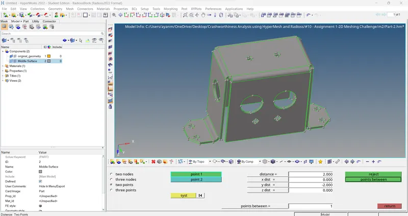
> Under the property menu the thickness ‘T’ has to be specified. (2mm)
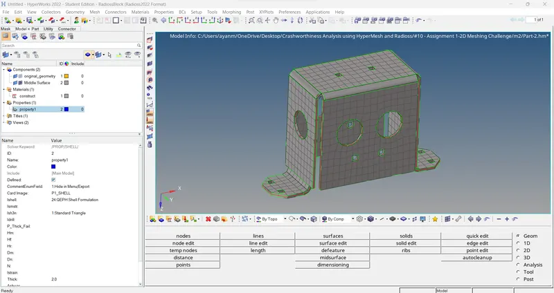
> FINAL MODEL VIEW....
> Without thickness FE..
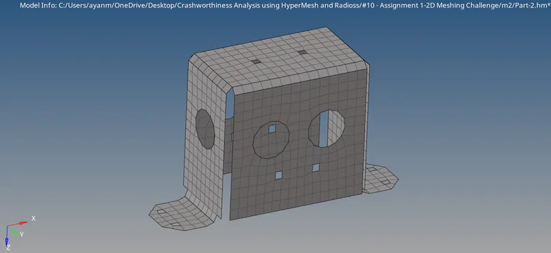
> With thickness FE..(2D Detailed Element Representation) -
MODEL _3 (Mounting Bracket) ->
All the steps carried out for Model_1 are also repeated for Model_3.
1) Import the model into Hypermesh.
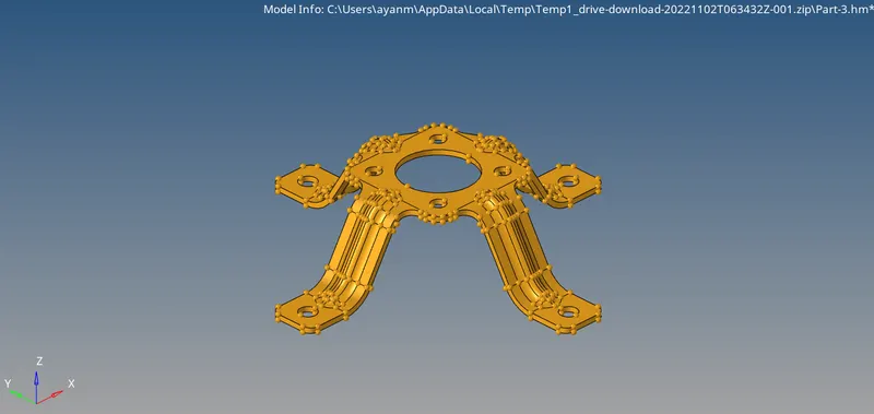
2) Mid surface extraction. -
3) Mid surface clean-up. –
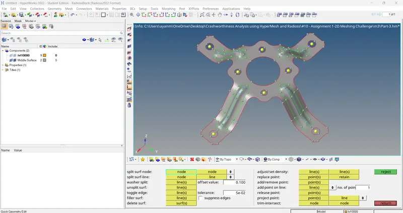
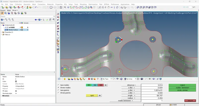
> For circle center..used Geom > distance (F4) > 3 nodes > create.
4) Meshing of midsurface. –
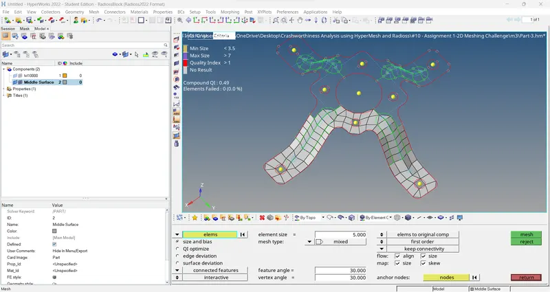
Since the model is symmetrical meshing can be done on one section and the elements can duplicated and position to obtain the mesh for the whole model.
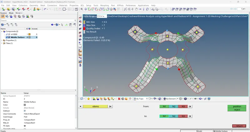
> for position elements to other side use.. Tool > position > elements(duplicated) > set co-ordinate position > position.
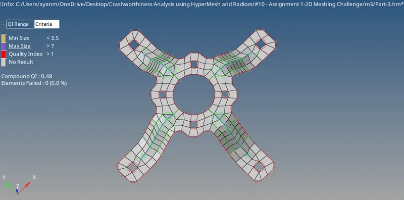
> Then used associate (F7) / project to surface or line (shift + F7) for set-up elements to surface. After that mesh remaining areas.
5) Ensuring quality of elements generated. –
6) Assigning thickness. –
> Measuring thickness of parent component.
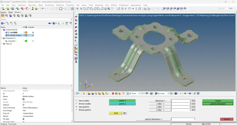
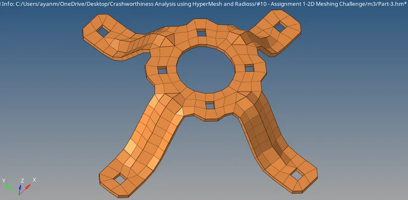
> Under the property menu the thickness ‘T’ has to be specified. (1.8mm)
> check for edges.
> check for normals.
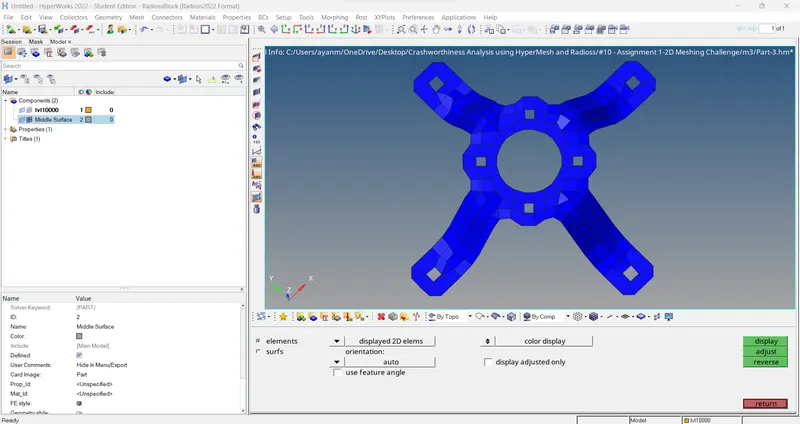
> FINAL MODEL VIEW....
> Without thickness FE..
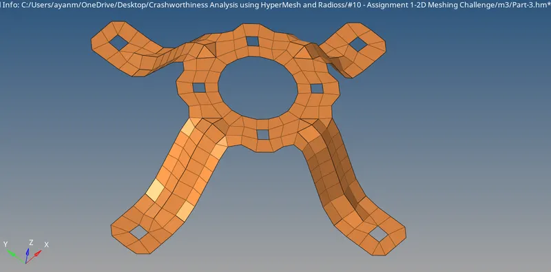
> With thickness FE..(2D Detailed Element Representation) -
CONCLUSIONs:
The given components were meshed according to the given quality criteria’s after extracting the midsurface. Also, the required thickness was assigned to the elements.
For model 1 & model 2, i go for capture all features so, some elements are failed.
And for model 3 i go for clear off elements so, some features regions are compromised.