Assignment 1-2D Meshing Challenge
Aim :-
To carry out the geometry cleanup operation and perform 2D meshing for the given 3 parts using Hypermesh with a target element size nof 5 units.
Quality Criteria :-
Target length = 5mm
Min Length = 3.5mm
Max Length = 7mm
Procedure :-
1. Import the CAD file to Hypermesh.
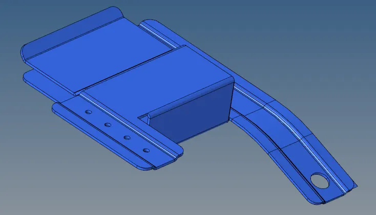
Fig 1.1 :- Imported Part 1 CAD File
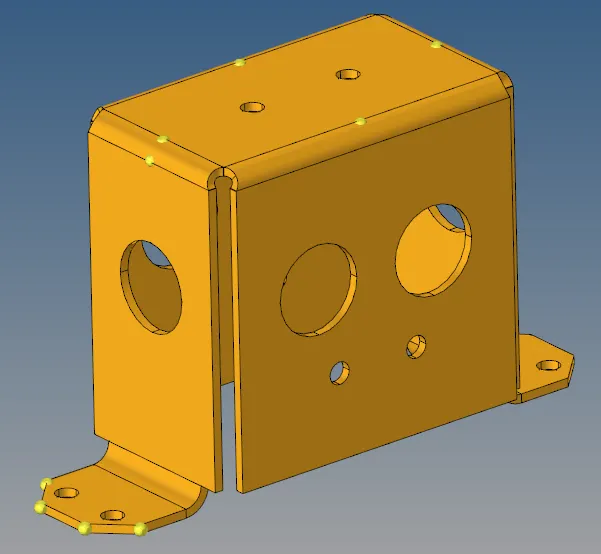
Fig 1.2 :- Imported Part 2 CAD File
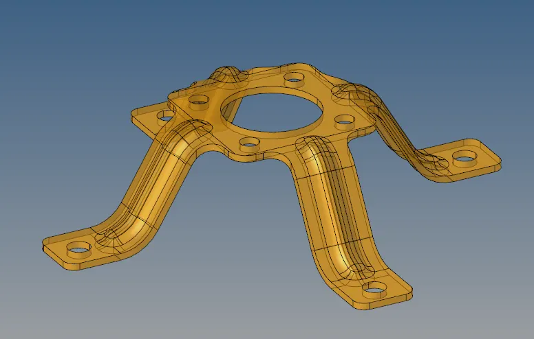
Fig 1.3 :- Imported Part 3 CAD File
2. Check for geometric errors like free edges, open surface, duplicate line/surfaces, solids etc. The lines in red are to be cleared using Geometry->Quick Edit->Toggle/Filler/Replace points->OK.
Yellow lines would be due to duplicate surface or additional edge joining, delete the duplicate edge using Geometry->Defeature->Duaplicates->Find->Remove or press F2->Select surface->Delete entity.
Also remove CAD lines which are too close, that results in elemental quality issues. Also fill holes which are less than 5 unit diameter as per the instruction given.
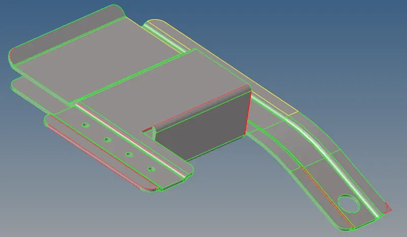
Fig 2.1 :- Geometrical error in Part 1
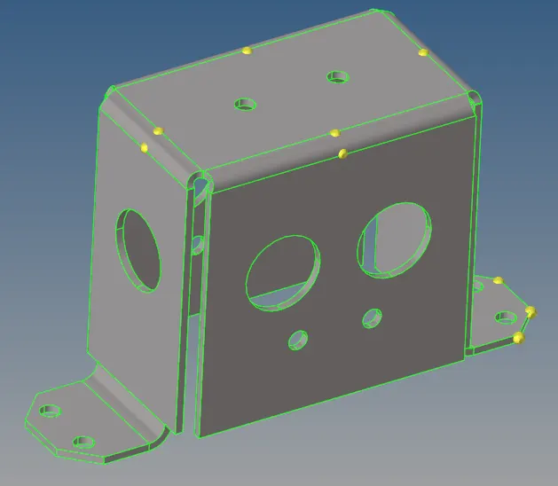
Fig 2.2 :- Geometrical error in Part 2
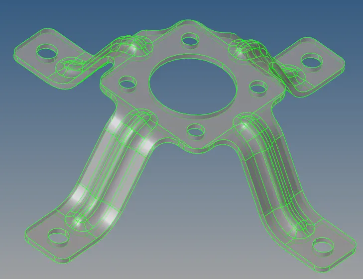
Fig 2.3 :- Geometrical error in Part 3
3. After performing the geometric clean up activity, check for any other errors. Clean CAD geometries are as shown in the below snap.
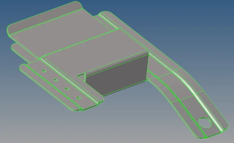
Fig 3.1 :- Clean CAD Geometry Part 1
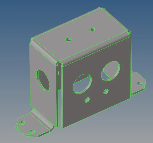
Fig 3.2 :- Clean CAD Geometry Part 2
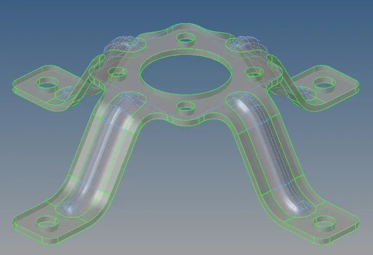
Fig 3.3 :- Clean CAD Geometry Part 3
4. Extract the mid surface of the component using Geometry->Midsurface->Automidsurface->Select the surface->Extract.
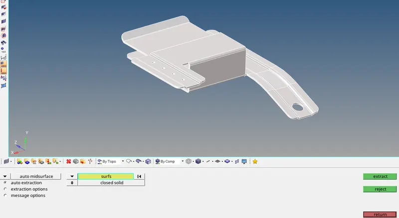
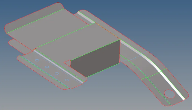
Fig 4.1 :- Midsurfacing for Part 1 Fig 4.2 :- Midsurface Part 1
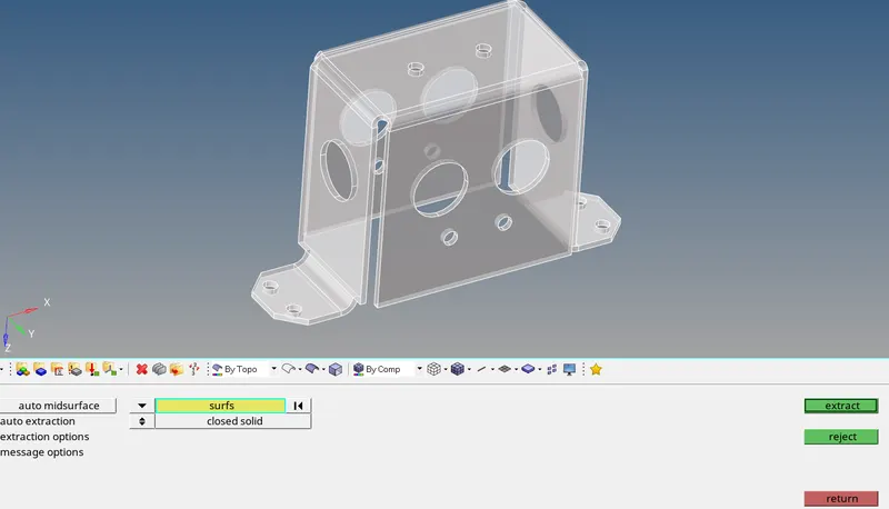
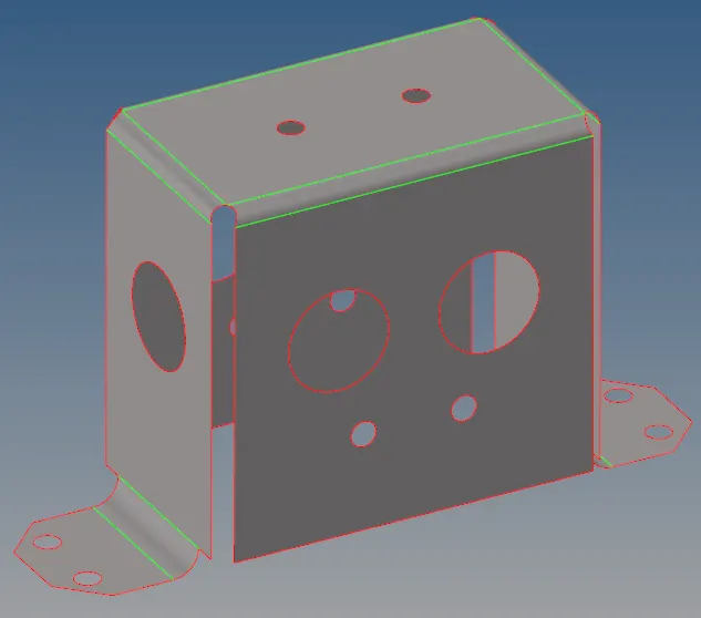
Fig 4.3 :- Midsurfacing for Part 2 Fig 4.4 :- Midsurface Part 2
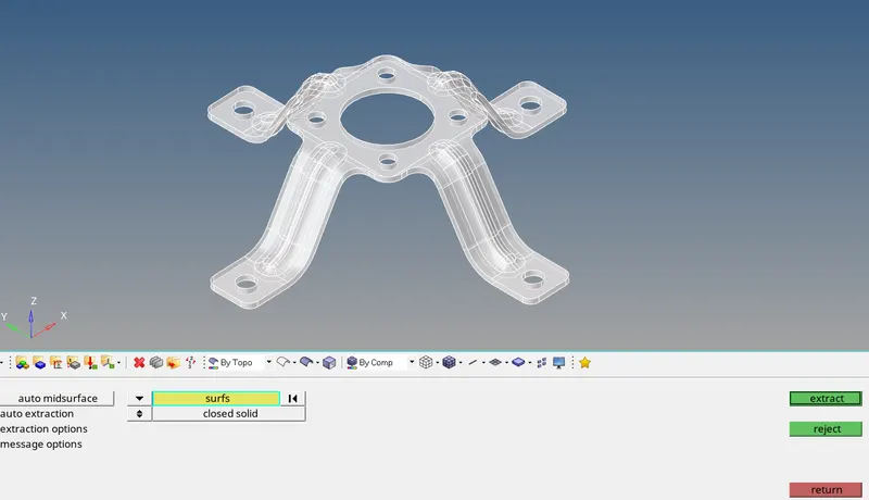
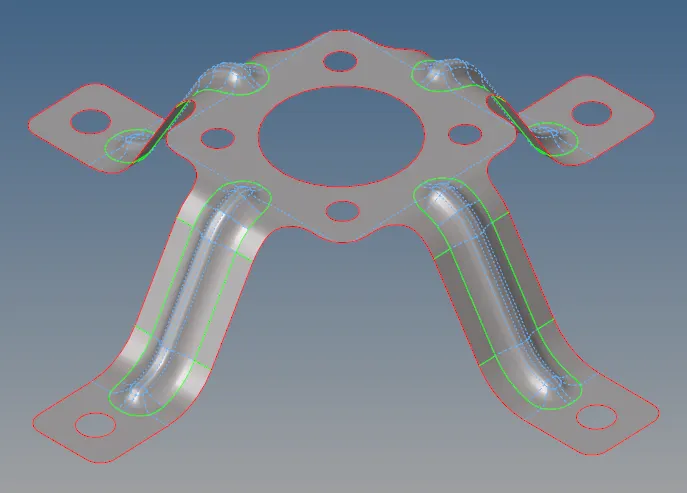
Fig 4.5 :- Midsurfacing for Part 3 Fig 4.6 :- Midsurface Part 3
5. Once the mid surface is extracted, perform meshing on the midsurface by 2D->Automesh->size and bias->element size=5->Select the surface->Mesh.
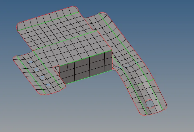
Fig 5.1 :- Meshing Part 1
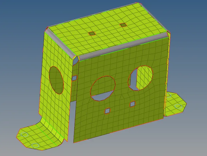
Fig 5.2 :- Meshing Part 2
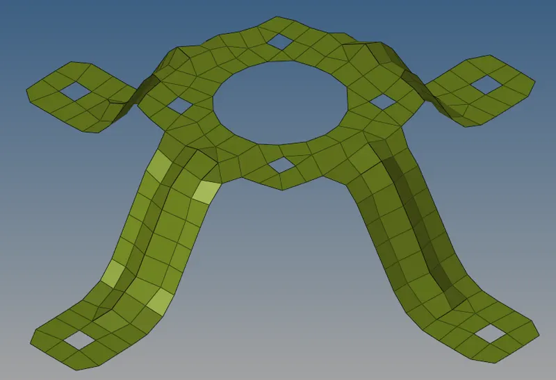
Fig 5.3 :- Meshing Part 3
6. Check for elemental failures by pressing F10->min/max length->save failed, then press F5->Elements->Retrieve->Mask.
Quality issues can also be cleared by 2D->Qualityindex->Cleanup tools. As shown in the below picture.

Fig 6 :- Quality Clean-up Tools
7. Check if there are any other quality issues.
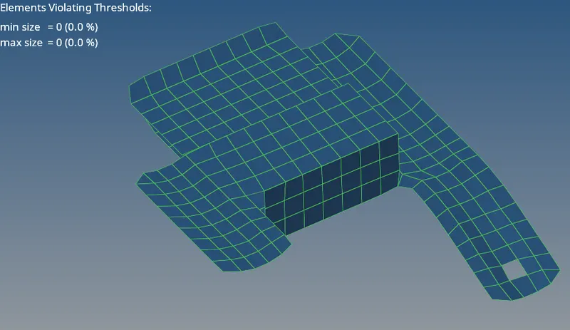
Fig 7.1 :- Quality Mesh Part 1
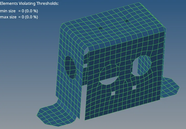
Fig 7.2 :- Quality Mesh Part 2
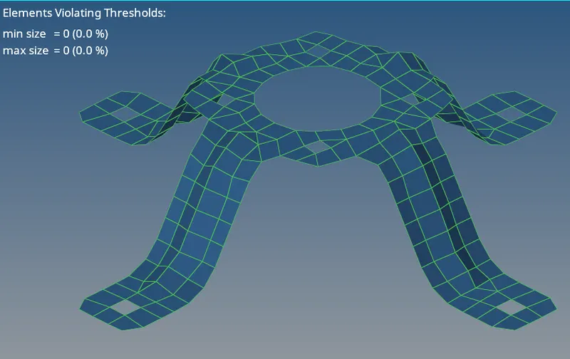
Fig 7.3 :- Quality Mesh Part 3
8. Assign generic property and material for the models.
Part 1 :- 0.91 unit Thickness
Part 2 :- 2.0 units Thickness
Part 3 :- 1.8 Units Thickness
Material would be selected M1_Elast for all 3 models with properties as below,
Rho_initial = 0.0028
E = 71000.0
Nu = 0.33
9. After assigning the property & material to the model, turn on thickness to check if it is matching with the CAD.
Also check if the property, material, part and component are proper by changing in Element color mode.
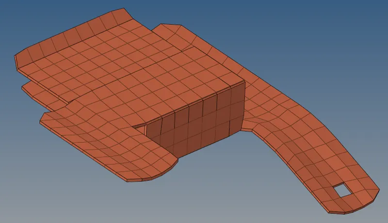
Fig 8.1 :- Property & Material added to Part 1
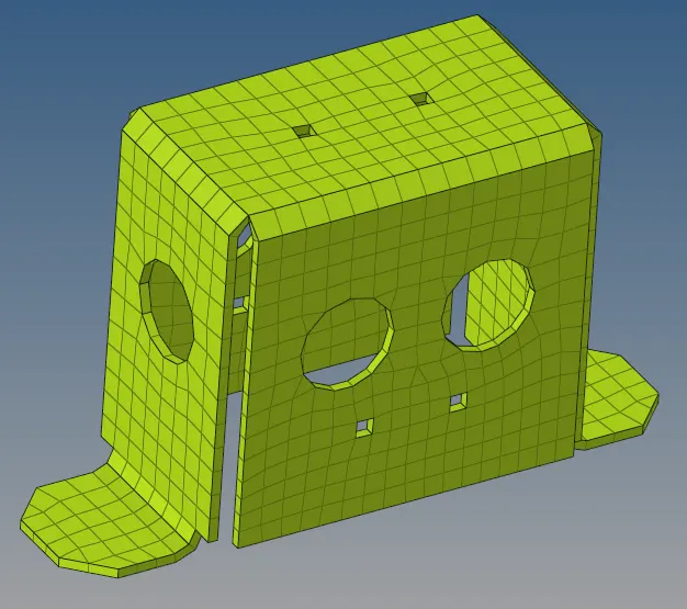
Fig 8.2 :- Property & Material added to Part 2
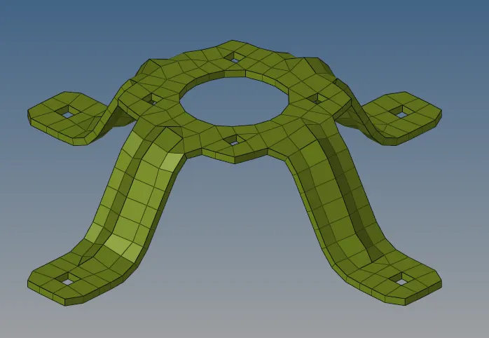
Fig 8.3 :- Property & Material added to Part 3
Result :-
The given 3 parts are processed and geometry clean-up, mid surface extraction, 2D emshing, Element quality, feature capturing, property & material assigning are done succesfully using Hypermesh tool.