Assignment 1-2D Meshing Challenge
OBJECTIVE:
- Clean the geometry.
- Extract midsurface.
- Clean midsurface geometry.
- Ignore holes less than dia 5mm.
- Create 2D mesh with target length 5mm, min 3.5mm max 7mm.
- And assign proper thickness, by creating a generic property.
PROCEDURE:
PART 1
Import the Given model to hypermesh using Import option.
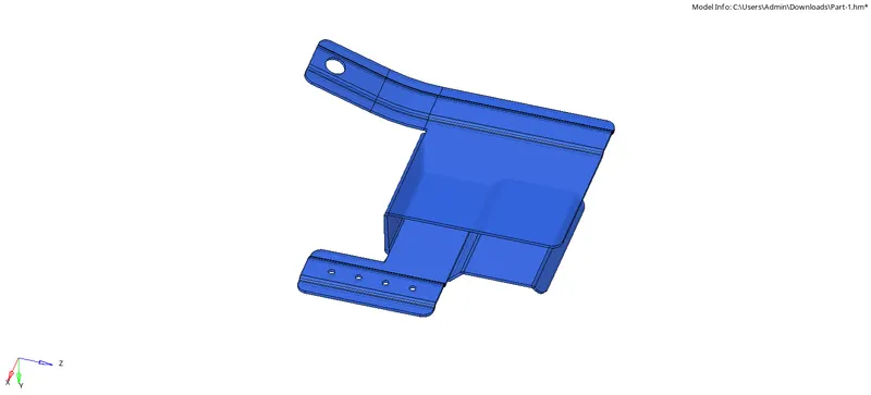
The model is viewed in topo mode to check for Geometry errors and free edges or any duplicate surface in the component.
Using the tools from the Geom menu the geometry of the model is cleaned up before extracting the midsurface.
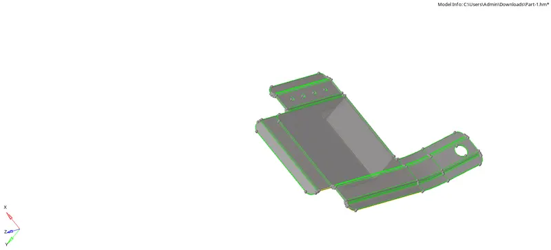
Filler surface is used to create any missing surfaces and fill holes that are not necessary.
Toggle option is used to clear disconnected edges and lines in surfaces that are small.
Replace point to retain a point in a surface to another point.
The midsurface is now extracted using either auto midsurface or the offset option in the surface edit menu.
The midsurface is extracted with offset+planes+sweeps and the surface is selected and midsurface is extracted from the model.
Next we need to findout if any surfaces will need to be defeatured to avoid minimum element error using defeature option in the geom menu
The holes having diameter less than 5mm are filled using filler surface and then the lines are toggled and suppressed.
To measure the diameter of the hole distance option from the Geom menu is used .
MESHING
After the midsurface is generated , we need to mesh the surface . Before meshing the quality criteria and paramters are filled in Preferences tool- Criteria file setting and parameter file settings.
The Automesh option under 2D is used to mesh the surface ad the element size is given as 5mm and the element type as mixed.
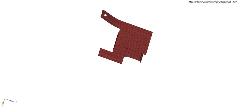
To obtain a finer meshflow and less trias the surface is split into smaller surfaces and then meshed.
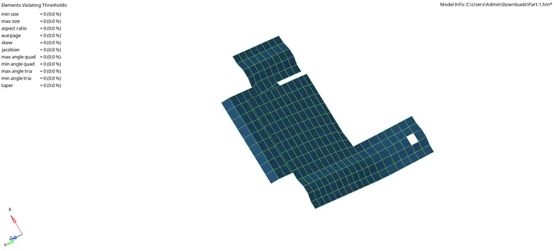
The meshed elements shoul satisfy the quality criteria. It is checked unded quality index option in 2D .
The elements violating the criteria is highlighted .Cleanup tools like drag tria elements, combine tria, Split squad, Optimize elements are used to cleanup the failed elements.
The automesh tool is also used to remesh the meshflow accordingly.
The above steps are followed until all the elements are satisfying quality criteria.
PROPERTY
After the component is meshed , we need to create a property and assign thickness. For that material should be created . right click on the tab bar and create-material.
Create -property and give thickness as necessary and assign material to the property. After that, right click on the midsurface and select assign and select property. Now the thickness is assigned.
PART 2
Import the Given model to hypermesh using Import option.
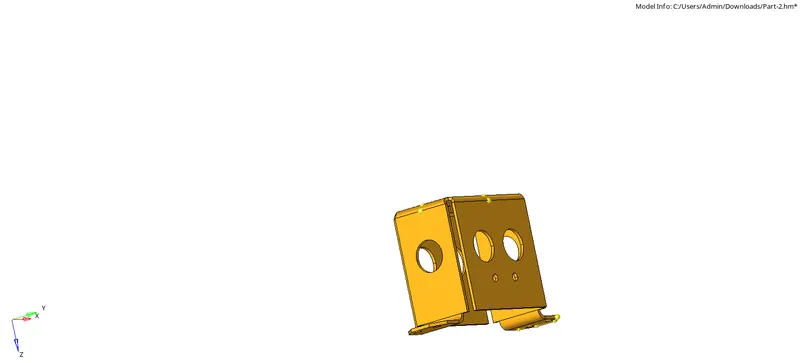
The model is viewed in topo mode to check for Geometry errors and free edges or any duplicate surface in the component.
Using the tools from the Geom menu the geometry of the model is cleaned up before extracting the midsurface.
Filler surface is used to create any missing surfaces and fill holes that are not necessary.
Toggle option is used to clear disconnected edges and lines in surfaces that are small.
Replace point to retain a point in a surface to another point.
The midsurface is now extracted using either auto midsurface or the offset option in the surface edit menu.
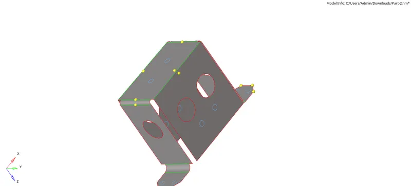
The midsurface is extracted with offset+planes+sweeps and the surface is selected and midsurface is extracted from the model.
Next we need to findout if any surfaces will need to be defeatured to avoid minimum element error using defeature option in the geom menu
The holes having diameter less than 5mm are filled using filler surface and then the lines are toggled and suppressed.
To measure the diameter of the hole distance option from the Geom menu is used .
MESHING
After the midsurface is generated , we need to mesh the surface . Before meshing the quality criteria and paramters are filled in Preferences tool- Criteria file setting and parameter file settings.
The Automesh option under 2D is used to mesh the surface ad the element size is given as 5mm and the element type as mixed.
To obtain a finer meshflow and less trias the surface is split into smaller surfaces and then meshed.
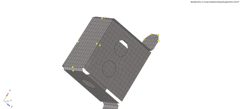
The meshed elements shoul satisfy the quality criteria. It is checked unded quality index option in 2D .
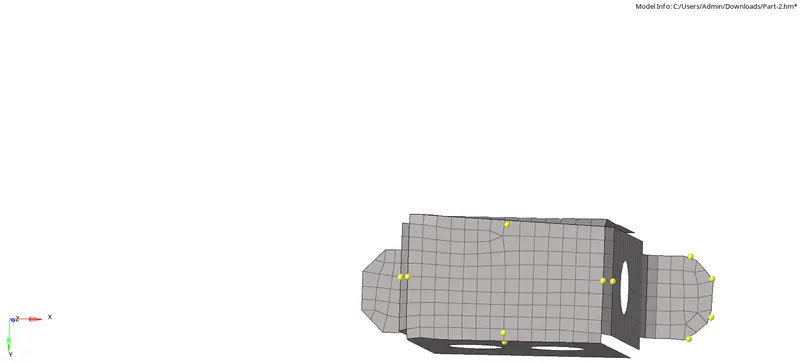
The elements violating the criteria is highlighted .Cleanup tools like drag tria elements, combine tria, Split squad, Optimize elements are used to cleanup the failed elements.
The automesh tool is also used to remesh the meshflow accordingly.
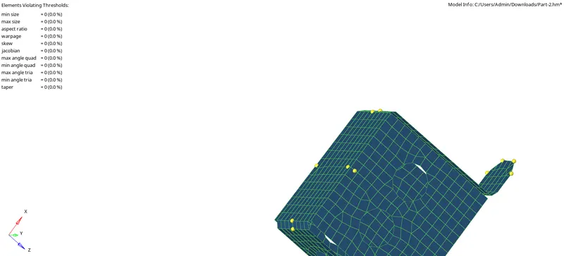
The above steps are followed until all the elements are satisfying quality criteria.
PROPERTY
After the component is meshed , we need to create a property and assign thickness. For that material should be created . right click on the tab bar and create-material.
Create -property and give thickness as necessary and assign material to the property. After that, right click on the midsurface and select assign and select property. Now the thickness is assigned.
PART-3
Import the Given model to hypermesh using Import option.
The model is viewed in topo mode to check for Geometry errors and free edges or any duplicate surface in the component.
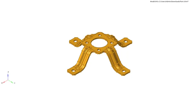
Using the tools from the Geom menu the geometry of the model is cleaned up before extracting the midsurface.
Filler surface is used to create any missing surfaces and fill holes that are not necessary.
Toggle option is used to clear disconnected edges and lines in surfaces that are small.
Replace point to retain a point in a surface to another point.
The midsurface is now extracted using either auto midsurface or the offset option in the surface edit menu.
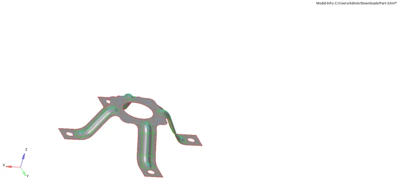
The midsurface is extracted with offset+planes+sweeps and the surface is selected and midsurface is extracted from the model.
Next we need to findout if any surfaces will need to be defeatured to avoid minimum element error using defeature option in the geom menu
The holes having diameter less than 5mm are filled using filler surface and then the lines are toggled and suppressed.
To measure the diameter of the hole distance option from the Geom menu is used .
MESHING
After the midsurface is generated , we need to mesh the surface . Before meshing the quality criteria and paramters are filled in Preferences tool- Criteria file setting and parameter file settings.
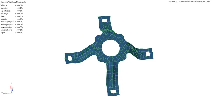
The Automesh option under 2D is used to mesh the surface ad the element size is given as 5mm and the element type as mixed.
To obtain a finer meshflow and less trias the surface is split into smaller surfaces and then meshed.
The meshed elements shoul satisfy the quality criteria. It is checked unded quality index option in 2D .
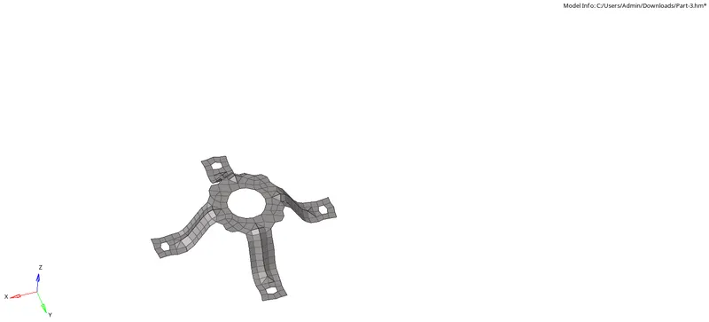
The elements violating the criteria is highlighted .Cleanup tools like drag tria elements, combine tria, Split squad, Optimize elements are used to cleanup the failed elements.
The automesh tool is also used to remesh the meshflow accordingly.
The above steps are followed until all the elements are satisfying quality criteria.
PROPERTY
After the component is meshed , we need to create a property and assign thickness. For that material should be created . right click on the tab bar and create-material.
Create -property and give thickness as necessary and assign material to the property. After that, right click on the midsurface and select assign and select property. Now the thickness is assigned.
CONCLUSION
Imported the Geometry and performed cleanup operations and midsurface is extracted and meshed with proper mesh flow and satisfying all the quality criteria and eloement quality and created property and assigned thickness.
LEARNING OUTCOMES
Midsurface extraction
Geometry cleanup
2D meshing
Maintaining element quality
Assigning thickness