Assignment 1-2D Meshing Challenge
2D Meshing
Aim -
- To perform pre-processing on the given three models according to the given requirements using hypermesh pre-processing software.
Objective -
- To do geometric clean-up on the given three models.
- To extract a mid surface for all the given three models.
- Defeaturing the edge fillets.
- To do geometric clean-up on the mid surface and eliminating the holes which are less than 5mm dia.
- Creating quality criteria for all three models.
- To do 2D meshing on all three models.
- Assigning thickness to all three models.
Procedure -
Model-1
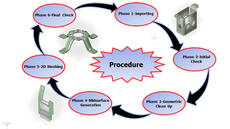
| Figure 1-Procedure. |
Phase 1-Importing
- Hence we are importing a given CAD geometry into hypermesh.
- There are file formats like IGES, STEP, Parasolid where we can import these file formats into any CAD, CAE Softwares.
- But in hypermesh student edition, we can only import three file formats like
- IGES [Initial Graphics Exchange Specification].
- STEP [Standard for the Exchange of Product Model Data].
- Solidworks.
- IGES, STEP, These two are standard file formats that are used most in industries. But nowadays in industries, they are also using Parasolid file format.
- While importing the file into the graphical user interface, Be sure whether the file is a .step or .iges file.
- File > Import > Import Model > File type > Open File > Import File.
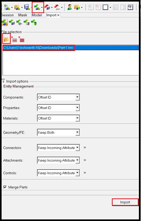
| Figure 2-Import Browser. |
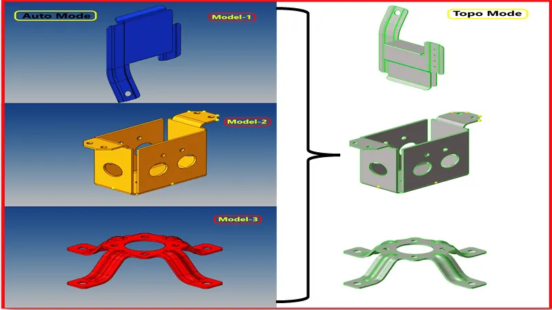
| Figure 3-Models Imported into GUI. |
- Switch to the topo mode and examine whether the solid exists in the component or not, If solids exist, Delete the solids cause we are doing 2d meshing on the component.
- You can find topo mode in the toolbar panel.
- Delete [F2] >> Solids >> Select by box selection >> Delete Entity.
- If solids exist, They will be highlighted in green color.
Example -
[Note: This Model is for only Example]
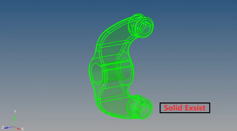
| Figure 4-Before Deleting the Solids |
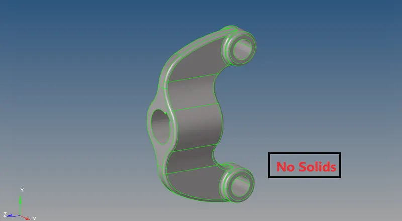
| Figure 5-After Deleting the solids |
Phase 2- Initial Check
- Before working on the model. We have to check the geometry if there are any errors like
- Damaged Geometry.
- Free edges in unnecessary areas.
- Unnecessary points on the lines.
- Unnecessary Connections and connectivity errors.
- By assessing model 1, There are some errors like
- Free Edges [Red Lines].
- T Junction Edges [Yellow Lines].
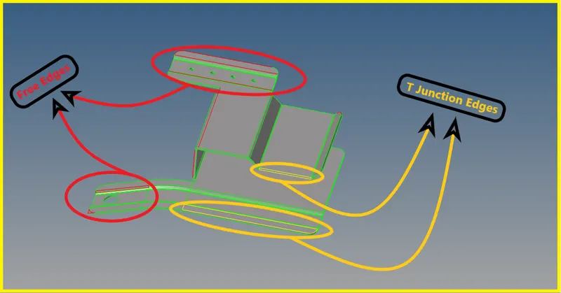
| Figure 6-Free and T Junction Edges. |
Phase 3-Geometric Clean Up
- There are some Free Edges and yellow T-Junction Edges in the model as shown in above figure 6, Fix them.
1) Use topology display tools to determine what needs to be fixed. For instance, to display the geometry by topo mode.
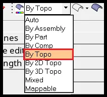
| Figure 7-Display Panel. |
2) Find duplicate surfaces and delete them.
- To delete duplicate surfaces, from the menu bar select Geometry >> Defeature >> Duplicates >> Select Surfaces >> By Displayed.
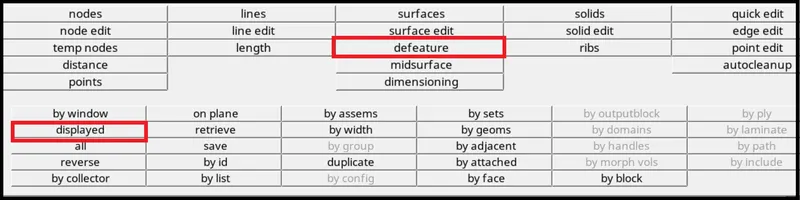
| Figure 8-Selecting the Surfaces by Displayed. |
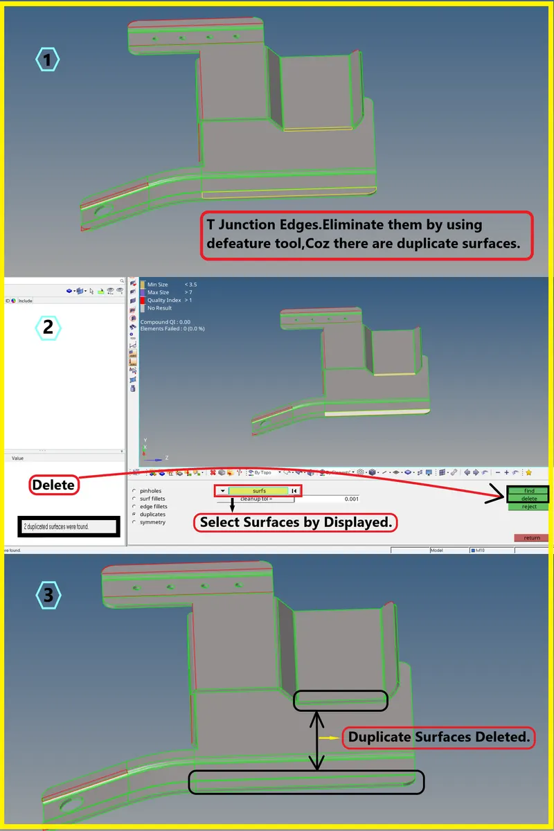
| Figure 9-Defeaturing Duplicate Surfaces. |
3) Use equivalence to combine as many free edge pairs as possible.
- Visually verify no surfaces were collapsed with this function.
4) Use the toggle to combine any remaining edges.
- Use replace if more control is needed.
5) Use a filler surface to fill in any missing surfaces.
6) The equivalence, toggle, and filler surface can be accessed within the Quick Edit panel.
- To access the Quick Edit panel, from the menu bar select Geometry >> Quick Edit.

| Figure 10-Quick Edit Panel. |
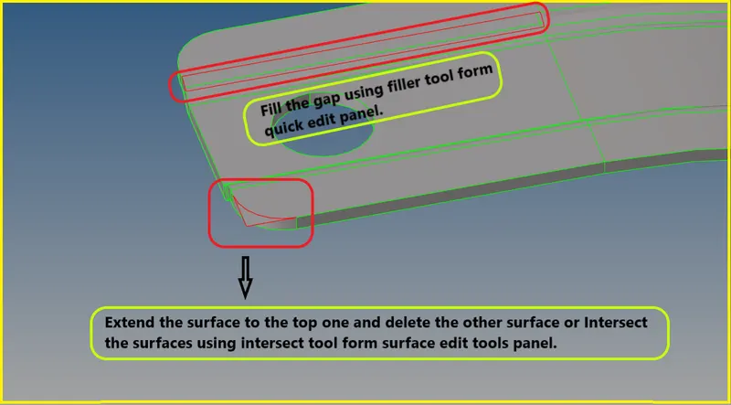
| Figure 11-Free Edges. |
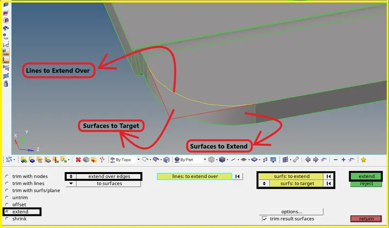
| Figure 12-Extending the Free Edges to Top Surface. |
- Here you can Self Intersect the surfaces by using Surface Edit Panel >> Trim with Surf/Plane >> Self Intersecting >> Select Surfaces.
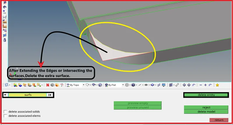
| Figure 13-Delete the Unwanted Surface. |
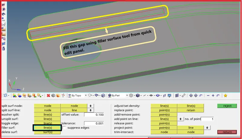
| Figure 14-Fill the Gap using Filler Surf Tool. |
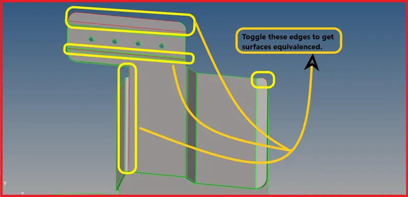
| Figure 15-Toggle these Edges to get Surface Equivalenced using Toggle Line from Quick Edit Panel. |
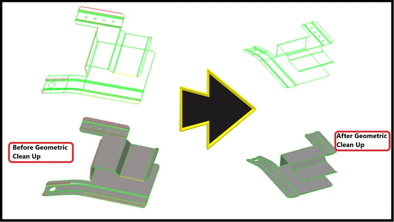
| Figure 16-Final Geometric Clean Up. |
Phase 4-Mid Surface Generation
- The mid surface has been extracted to the components which have less than 6mm thickness.
- We will be extracting mid-surface for the sheet metal and plastic components.
- This component's thickness is 0.91mm, So mid-surface extraction is needed for this component.
Why Extract Mid Surface?
- Before extracting the mid surface for every component, We should measure the thickness of the component, and then we have to proceed to extract the mid surface. If the component thickness is less than 6mm then we will come to know it is a sheet metal component or plastic Component.
- For sheet metal and plastic components, Mid Surface extraction is a must.
Midsurfacing: Process & Strategy-
1. Obtain a closed volume of surfaces or solids
- Midsurface: auto mid surface requires an enclosed volume.
- Use topology repair techniques if needed.
2. For complex parts, try defeaturing the surface defining the volume
- This simplifies the part and may give better results with creating solid.
3. Generate the mid surface using mid surface: auto mid surface
- Use surface pair for areas that need more control.
- Use mid surface: editing tools for mid surfaces that need fine-tuning.
4. View the mid surface and correct errors using the mid surface editing functionalities
- Can generally use quick edit.
4:1 Extract the Mid Surface
- For this component, I'm using auto extraction with the skin offset.
- In some cases, skin offset might work or might not work.
- For this component, I have used skin offset, Cozz is a sheet metal component.
- To Extract Mid Surface,Go to Geometry >> Mid Surface >> Auto Extraction >> Surface >> Extraction Option:Skin Offset >> Extract.

| Figure 17-Mid Surface Panel. |
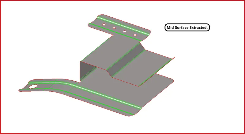
| Figure 18-Mid Surface Extracted. |
4:2 Geometric Clean Up on Mid Surface
- After extracting the mid surface, we have to do some manual clean-up before meshing.
- If your feature line is failing for the minimum length, then toggle that line or extract the midline to capture the feature line.
- If mid-line extraction doesn't work, then toggle that feature, coz there will be no options.
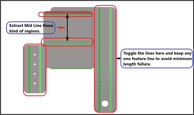
| Figure 19-Toggle the Lines and Extract the Mid Line in Appropriate Regions. |
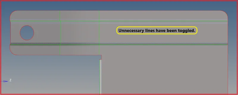
| Figure 20-Unnecessary Lines have been Toggled. |
- To Extract Mid Line,Go to
- Geometry >> Lines >> Midlines >> Line List 1,2 >> Create.
- We can use the Midline subpanel to create lines by interpolating between existing lines.

| Figure 21-Midline Sub Panel. |
- Now extract the midline for every region.
- And to project that lines to the mid surface.
- Use trim with lines tool to project on the mid surface.
- Make sure to set mid surface component as a current component, Then only the lines will exist in that component.
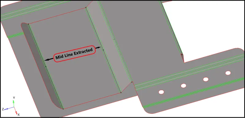
| Figure 22-Mid Line Extracted. |
- Now project the Midlines extracted to the surface using trim with lines from the surface edit tool.
- And toggle the other two lines and keep the midline only and go on.

| Figure 23-Surface Edit Panel. |
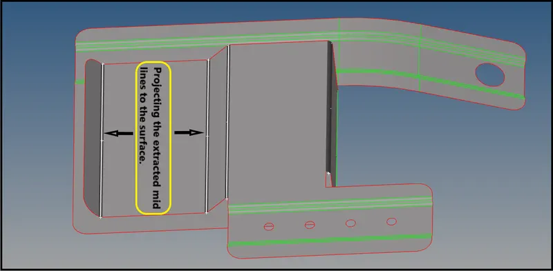
| Figure 24-Projecting the extracted midlines to the surface. |
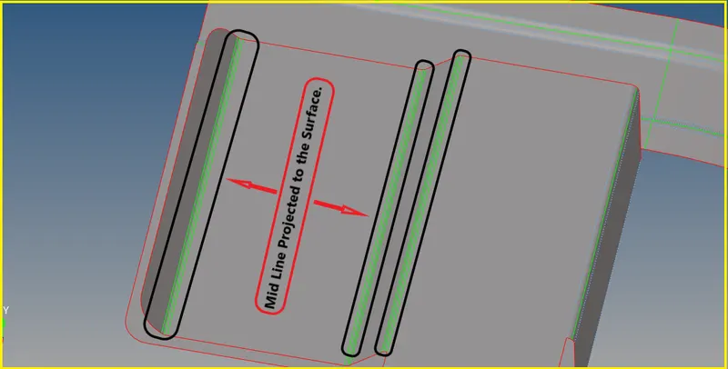
| Figure 25-Mid Line Projected to the Surface. |
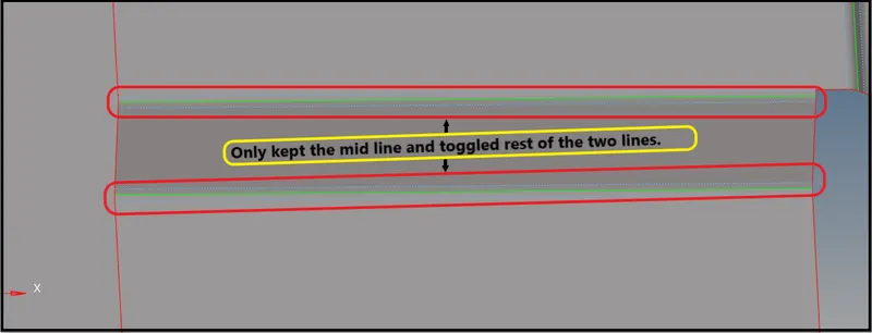
| Figure 26-Only Kept Mid Line and Toggled Rest of the Two Lines. |
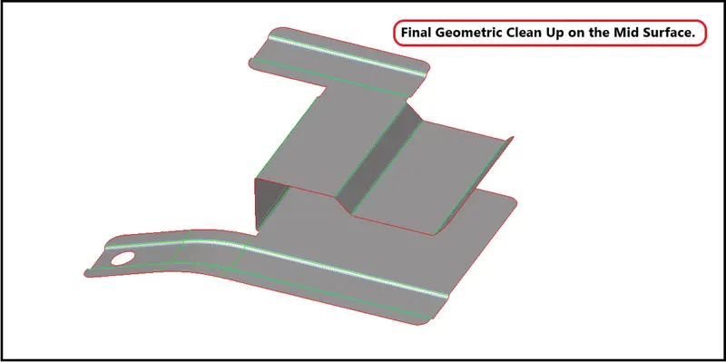
| Figure 27-Final Geometric Clean Up on the Mid Surface. |
Phase 5-2D Meshing
- Once geometry cleanup is completed (e.g. surfaces are stitched together — no unwanted free surface edges inside the geometry), meshing is next.
Some rules of thumb when meshing:
- The mesh should look rather smooth and regular (keep in mind that the analysis is based on your mesh and the mesh quality is key.
- Use the simplest element type suited for the problem.
- Start with a coarse mesh and understand the modeling results; then use a finer mesh if needed.
- Try to keep mesh-related uncertainties to a minimum if possible. Keep it simple as it can get more complicated on its own.
5:1 Enter the quality criteria that they given for the component's
- Toolbar → preferences → criteria file settings → checks for the element criteria →Enter values → apply → ok.
- Before generating a mesh on the surfaces. Enter the quality criteria given to us in the question.
- You can go and enter quality criteria in Toolbar → preferences → criteria file settings → checks for the element criteria →Enter values → apply → ok.
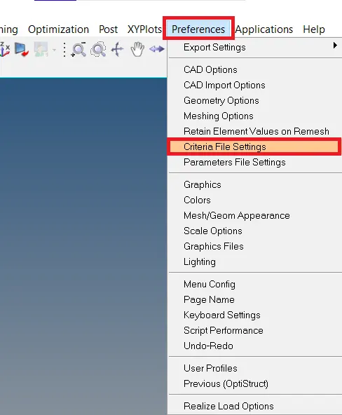
| Figure 28-Tool Bar Panel. |
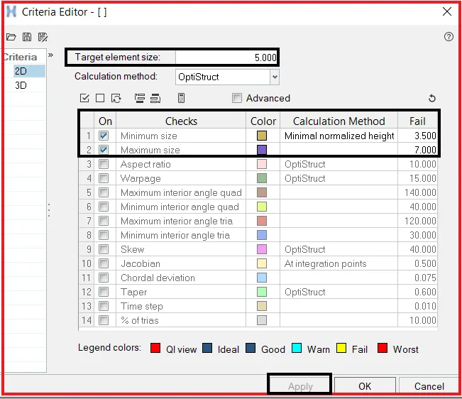
| Figure 29-Quality Criteria Panel. |
[Note: Save the criteria file settings for that component and save it any other drives, Cause whenever we open that component, we can open the element criteria file, and criteria will be applied habitually instead of entering again.]
Target Element Size - 5 Units
| S.No | Quality Criteria | Function/Definition | Value |
| 1 | Min Length | The shortest length of any given element | 3.5 |
| 2 | Max Length | The longest length of any given element | 7 |
5:2 Conditions to be followed while meshing
- Feature Capturing
- Feature capturing is a must while meshing. All the nodes must be connected to the shared edges.
- Tria Management
- Avoid a higher number of trias.
- Important Parameter's in tria management
- No trias in corners or edges.
- No opposite trias.
- No back-to-back trias.
- No trias in fillets or hemmings(We can have a minimum but anyhow try to avoid).
- No rotational quads.
- No trias should share a boundary with a feature line.
- Connectivity between elements.
- Split and perform the mesh.
- Use mixed type mesh for irregular-shaped surfaces and quads only for rectangular/square surfaces(Opposite sides should be parallel and equal).
5:3 Begin meshing the surfaces
- Start meshing from the center regions or from the least free edges. You will get proper mesh density and proper mesh flow.
Why Meshing is Needed?
- The finite Element Method reduces the degrees of freedom from infinite to finite with the help of discretization or meshing (nodes and elements). One of the purposes of meshing is to actually make the problem solvable using Finite Element. By meshing, you break up the domain into pieces, each piece representing an element.
How to Begin Mesh?
- Start meshing from the least free edges, Like start meshing from the center.
- It will be easy to get proper mesh flow and we will get uniform mesh density.
- Don't mesh from the edges, It will be difficult and you will get much error, So start meshing from the center.
- Choose the element type while meshing.
- For this component, we will be using mixed element type and working on it.
- We can also quad element type. This type can be used when we have a rectangular surface.
- We can use the Tria Element type. This type can be used for 3d tetra meshing.
Start Meshing
- Now start meshing on the surfaces,Go to 2D >> Automesh Panel >> Surfaces >> Element size = 4mm > Mesh Type : Quads or Mixed > Check for align and size > Mesh.

| Figure 30-Automesh Panel. |
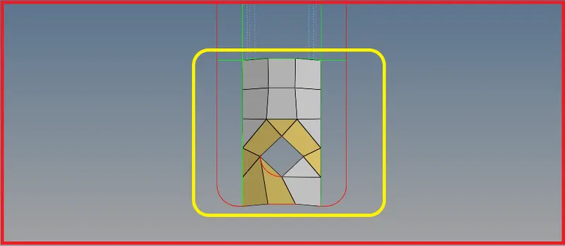
| Figure 31-Meshed Region with Element Failures. |
- Here to fix the mesh flow is not proper and elements are failing for the minimum length.
- To fix this failure, Use the rotate tool to face the element edge parallel to the free edge.
- To use rotate tool,Go to Tool >> Rotate >> Nodes >> Rotate +.
- Before using the rotate tool, Create a center node using the arc center tool from geometry, This node will be used as the base node while rotating.
- To create center node,Go to geometry >> Nodes >> Arc Center >> Lines >> Create.

| Figure 32-Rotate Tool. |
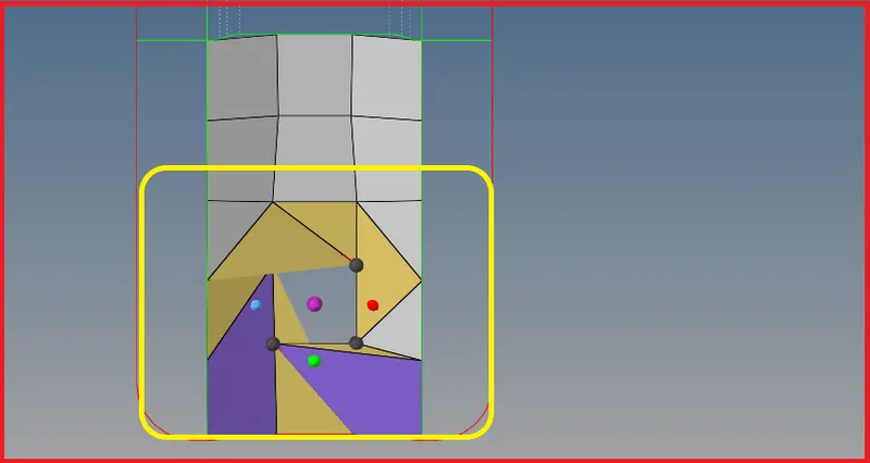
| Figure 33-Rotating the nodes to face element edge parallel to the free edge. |
- After rotating remesh the region.
- While meshing select the anchor nodes and mesh the region, Cozz if you select the anchor nodes and mesh, the nodes will be fixed and there will be no movement of nodes while meshing.
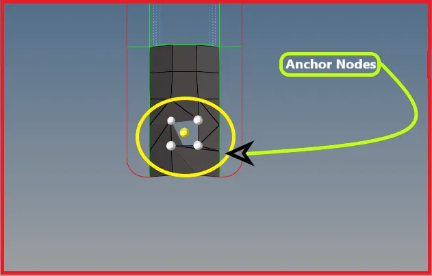
| Figure 34-Selected Anchor Nodes. |
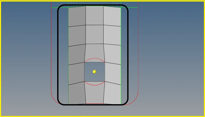
| Figure 35-After Rotating the Nodes and Remeshing the Elements. |
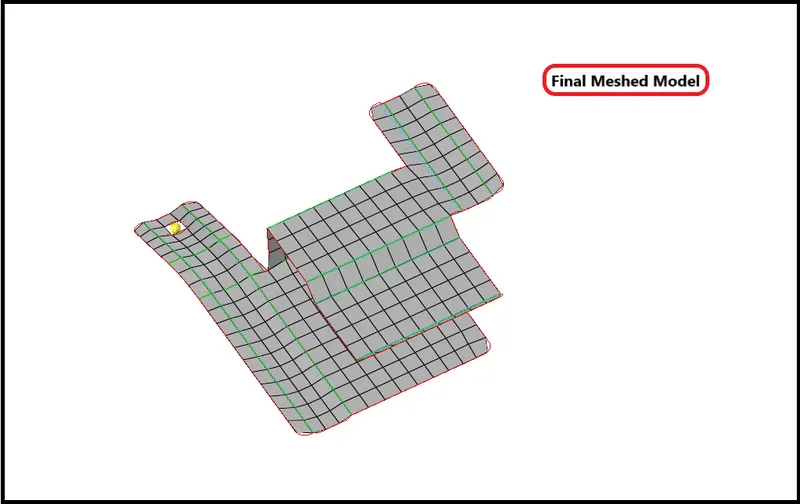
| Figure 36-Final Meshed Model. |
5:4 Assigning Thickness
- First Create a property on the browser.
- To create a property,Right click on browser >> Create >> Property.
- After Creating a property rename it and start assigning thickness to the component.
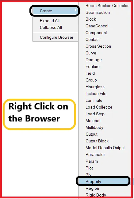
| Figure 37-Browser Panel. |
- After Creating the property, Give a thickness value in the thickness tab.
- And assign that property to the mid surface.
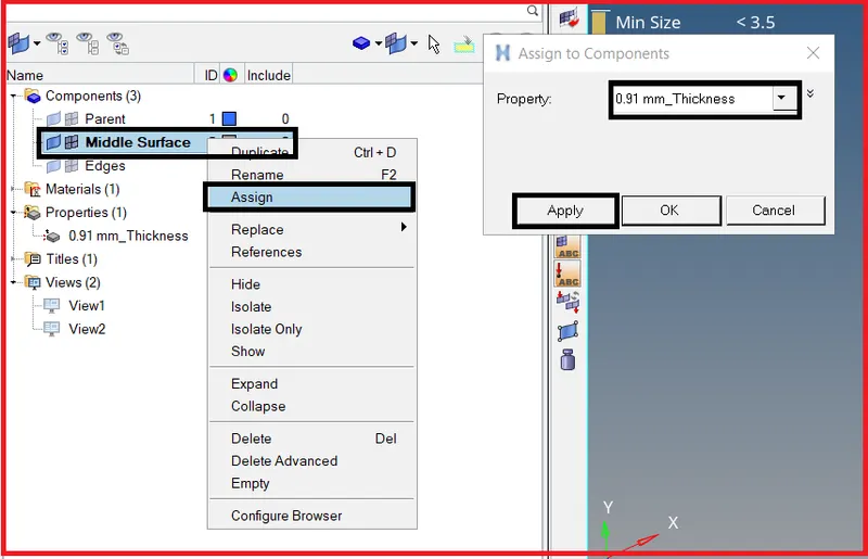
| Figure 38-Assigning Thickness. |
Phase 6-Final Checks
- Now after meshing the entire component and assigning the thickness to the component, Check for
i) Connectivity [Free Edges]
ii) Duplicates
iii) Normals
i) Check for Connectivity [Free Edges]
- Edge Tool will help us to find this error.
- Go to Too >> Edge >> Elements >> Find Edges.

| Figure 39-Edges Panel. |
- If we get the edges with connectivity, there is no problem, If you get edges without connectivity, then you have to manually connect them using replace tool.
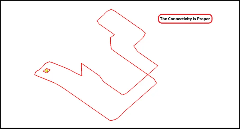
| Figure 40-Free Edges have been obtained to represent there is well connectivity. |
ii) Check for Duplicates
- Now check for the duplicate elements
- To check duplicates,Go to Tool >> Check Elements >> Duplicates.
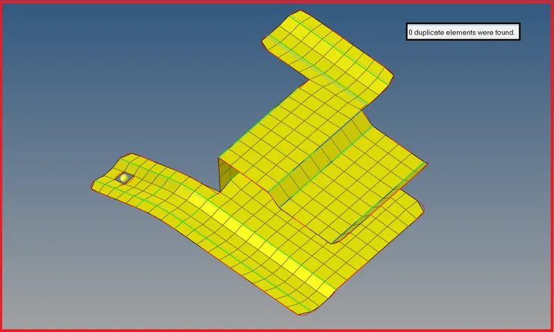
| Figure 41-0 Duplicate Elements. |
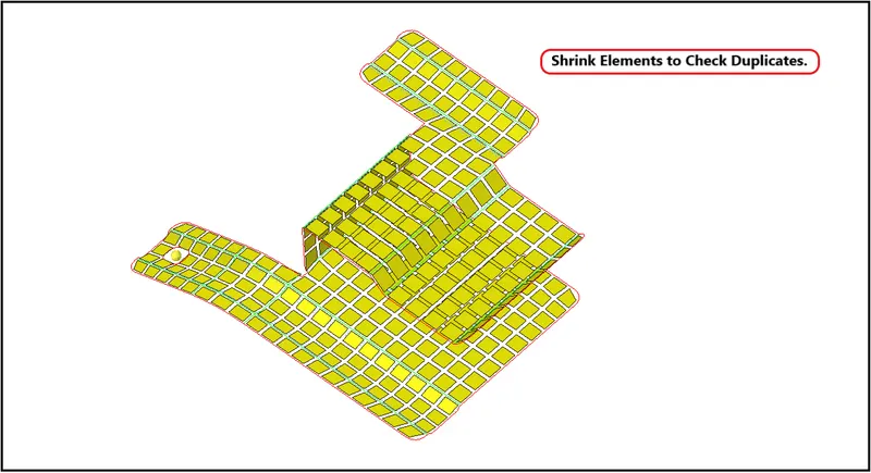
| Figure 42-Shrink Elements to Check Duplicates. |
iii) Check for Normals
- We can Use the Normals to display and reverse the normals of elements or surfaces. The orientation of element normals can also be adjusted. The normal of an element is determined by following the order of nodes of the element using the right-hand rule.
- Normals can be reviewed showing a vector or by colors. A vector shows in the positive normal direction, while the color mode shows the positive side of a shell or surface in red and the negative side in blue.
- To check normals go to Toolbar >> Mesh >> Check >> Elements >> Normals.
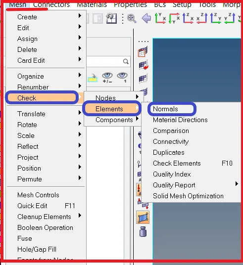
| Figure 43-Check for Normals. |

| Figure 44-Normals Panel. |
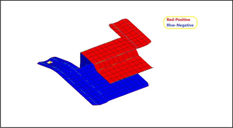
| Figure 45-Check for Normals. |
- Now Switch to the 2D Detailed Element Representation and check, Whether the thickness has been assigned to the component or not.
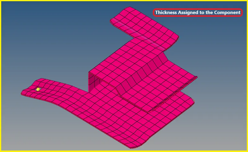
| Figure 46-Thickness Assigned to the Component. |
[Note: Similarly, the procedure is the same for the other two models, Do the same thing for the other two models also.]
Model-2
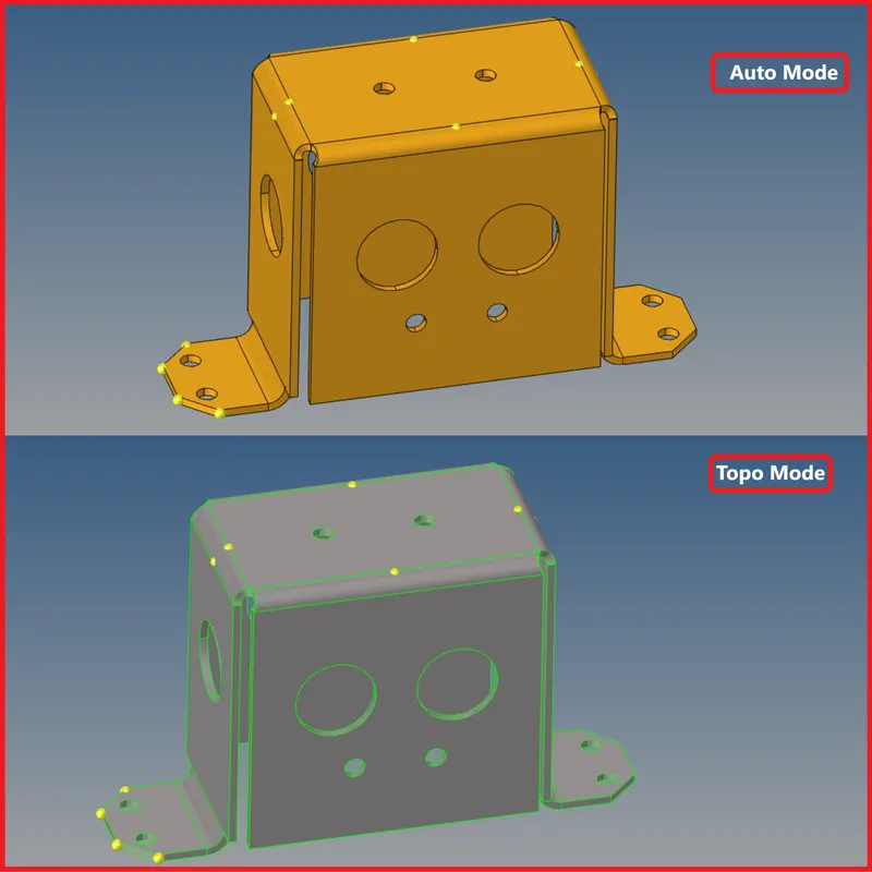
| Figure 47-Model Imported into GUI, Auto, and Topo Mode. |
Mid Surface Generation-
- Extract a mid surface for this model using skin offset in extraction options.
- Eliminate the holes which are less than 5mm dia.
- Eliminate the holes by using an unsplit surface.
- Replace the points which are very near to each other.
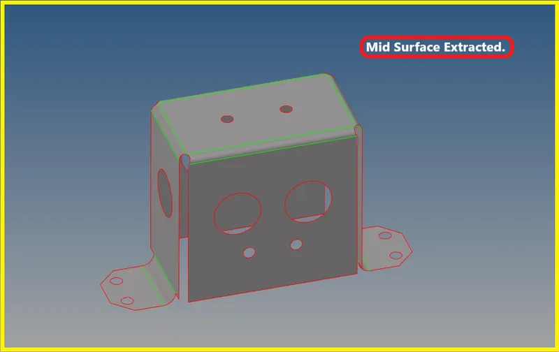
| Figure 48-Mid Surface Extracted. |
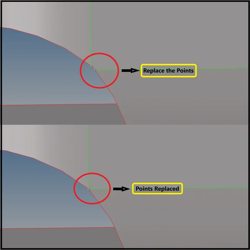
| Figure 49-Replacing the Points. |
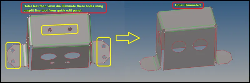
| Figure 50-Eliminating the Holes less than 5mm dia. |
Perform Mesh on the Surfaces
- Now after extracting the mid surface and performing geometric clean up on the mid surface, Mesh the surfaces according to the given quality criteria.
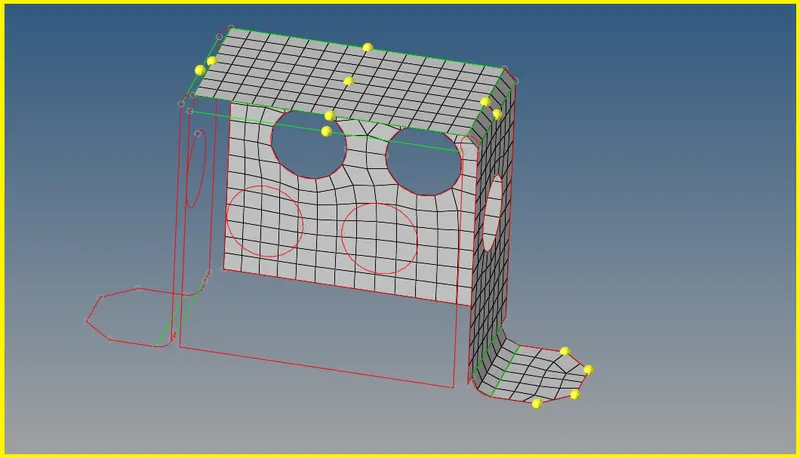
| Figure 51-Meshed Surfaces. |
- Now reflect the elements to the other side of surfaces using reflect from the tool panel.
- While reflecting make sure to make the elements duplicates and reflect them.

| Figure 52-Tool Panel. |
- While reflecting the elements select the base node and switch to the appropriate axis and then reflect the elements.
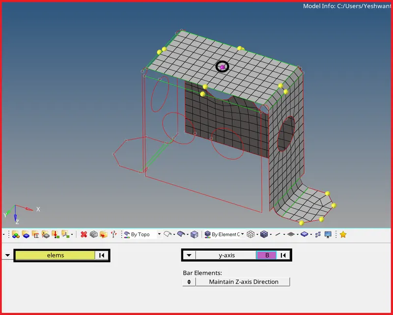
| Figure 53-Reflecting the Elements. |
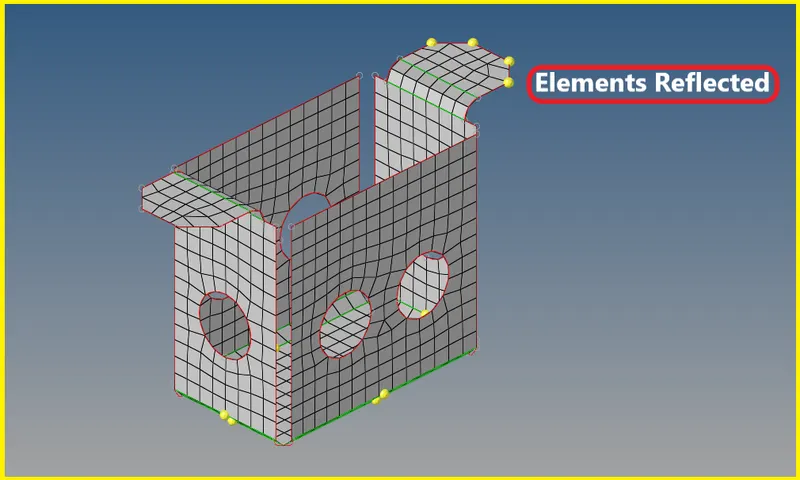
| Figure 54-Elements Reflected. |
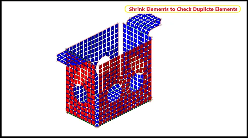
| Figure 55-Shrink Elements to Check Duplicates. |
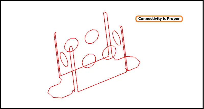
| Figure 56-Free Edges have been obtained to represent there is good connectivity. |
- Next check for the normals.
- To check normals go to Toolbar >> Mesh >> Check >> Elements >> Normals.
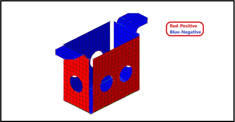
| Figure 57-Check for Normals. |
- Now Switch to the 2D Detailed Element Representation and check, Whether the thickness has been assigned to the component or not.
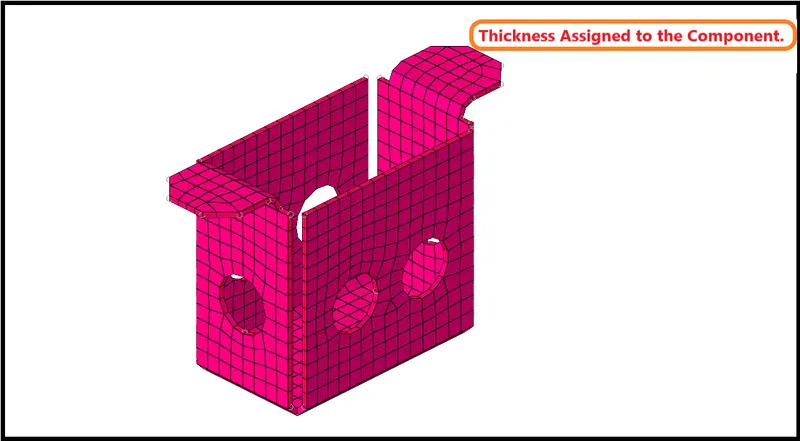
| Figure 58-Thickness Assigned to the Component. |
Model-3
- Hence the model is imported into the GUI.
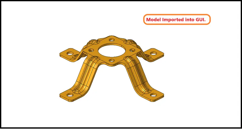
| Figure 59-Model Imported into GUI. |
- Now switch the topo mode and see whether there are any geometric errors or not, if not proceed with extracting mid surface.
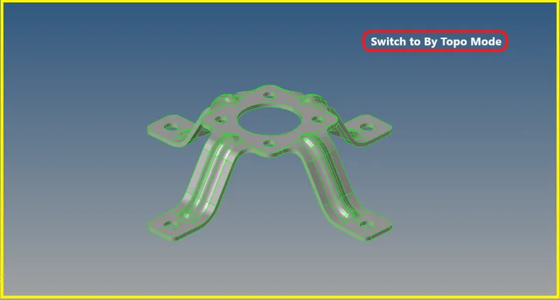
| Figure 60-By Topo Mode. |
Mid Surface Generation
- Extract a mid surface for this model using skin offset in extraction options.
- Eliminate the holes which are less than 5mm dia.
- Eliminate the holes by using an unsplit surface.
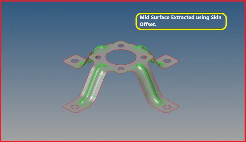
| Figure 61-Mid Surface Extracted. |
- Now after extracting the mid surface, Do a geometric clean-up on the mid surface.
- Eliminate the holes which are less than mm dia using the unsplit line tool from the quick edit panel.

| Figure 62-Eliminate the holes less than 5mm dia. |
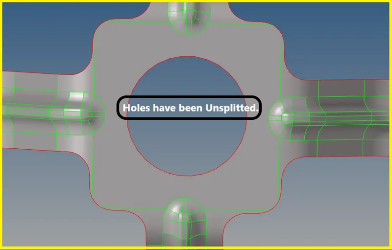
| Figure 63-Holes Unsplitted. |
- Now after eliminating the holes which are less than 5mm dia, Defeature the edge fillets to get the proper mesh flow.
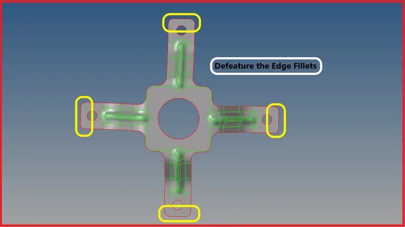
| Figure 64-Defeature the Edge Fillets. |
- To defeature the edge fillets.
- Go to Geometry Defeature >> Edge Fillets >> Select Surfaces By Displayed >> Give min and max radius >> Find >> Remove.

| Figure 65-Geometry Tool Panel. |

| Figure 66-Defeature Tool. |
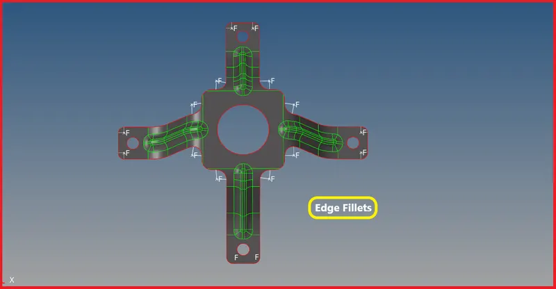
| Figure 67-Edge Fillets. |
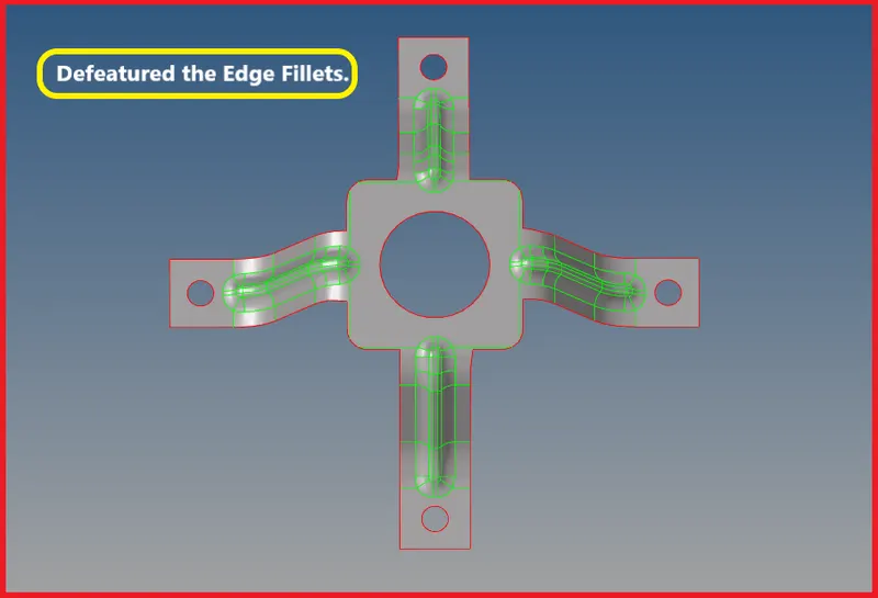
| Figure 68-Defeatured Edge Fillets. |
- After defeaturing the edge fillets, Extract the Mid Line on the top surface fillet regions to capture the feature properly.
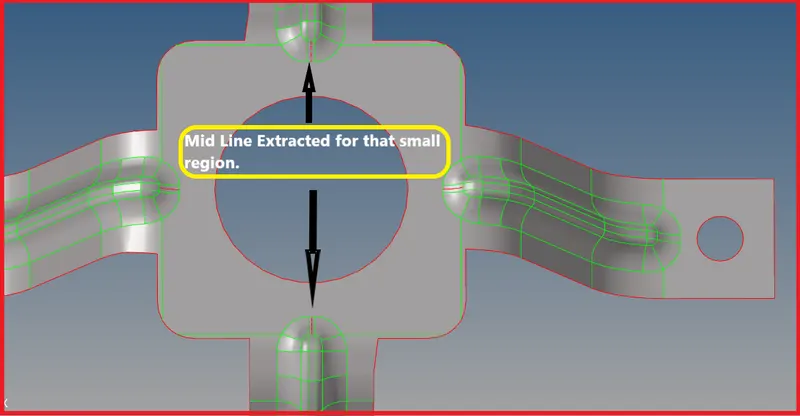
| Figure 69-Mid Line Extracted for the Small Region. |
- Here the midline has been extracted for only that small region, After projecting that midline to the surface, You can extract a midline completely for that fillet region using the split surface line.
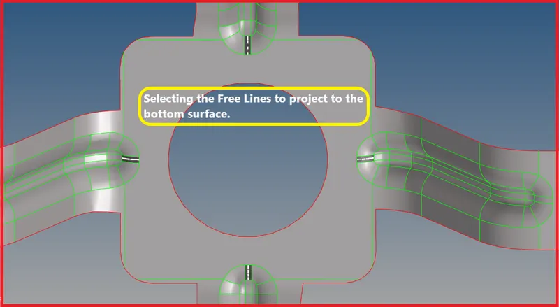
| Figure 70-Selecting the Free Lines to Project to the Bottom Surface. |
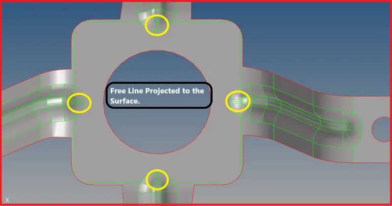
| Figure 71-Free Lines Projected to the Surface. |
- Now to extract a midline for the whole fillet region, Use Split Surface Line from the Quick Edit Panel.
- Select the Node and line, It will Split a surface from a selected node to a selected line, such that the resulting split is perpendicular to the line chosen.
- Node Line-Select a node and a line to split the surface. Additional splits require you to select a new node and line.
- Node Lines-Select a node and a line to split the surface, and select additional lines to continue to split surfaces based upon the split point (node) on the previously chosen line. Middle mouse click to finish this string of node selections.
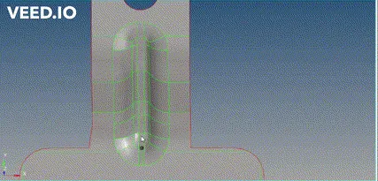
| Figure 72-Extracting the Mid Line using Split Surface Line. |
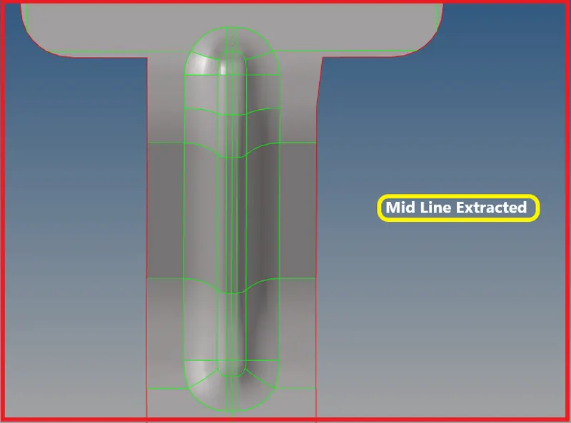
| Figure 73-Mid Line Extracted. |
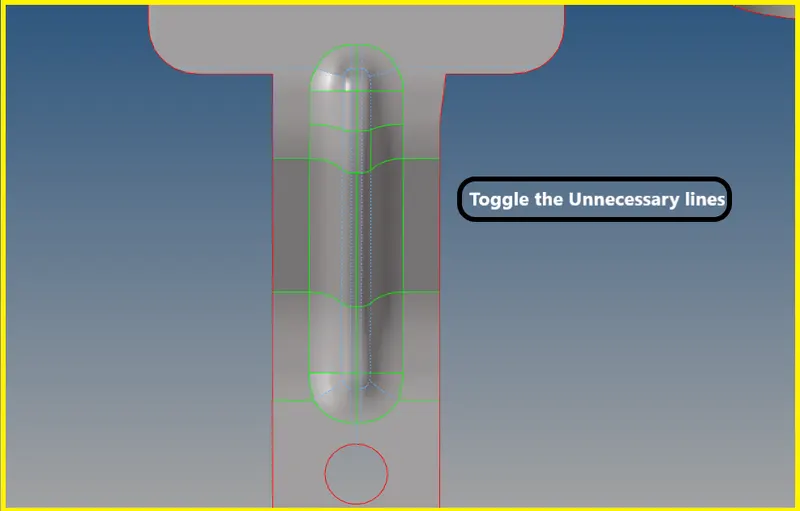
| Figure 74-Toggle the Unnecessary Lines. |
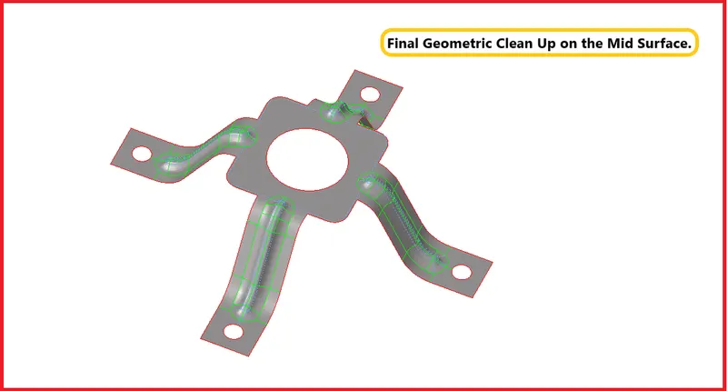
| Figure 75-Final Geometric Clean Up on the Mid Surface. |
Perform Mesh on the Surfaces
- Now after extracting the mid surface and performing geometric clean up on the mid surface, Mesh the surfaces according to the given quality criteria.

| Figure 76-2D Panel. |

| Figure 77-Automesh Panel. |
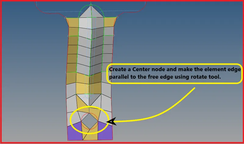
| Figure 78-Meshed region with Element Failures. |
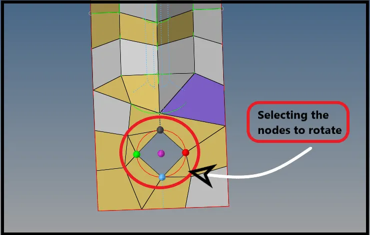
| Figure 79-Selecting the nodes to rotate. |
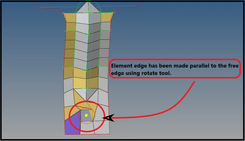
| Figure 80-Element Edge Made Parallel to Free Edge. |
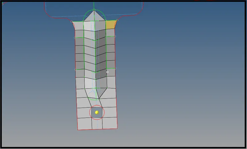
| Figure 82-Proper Mesh Flow. |
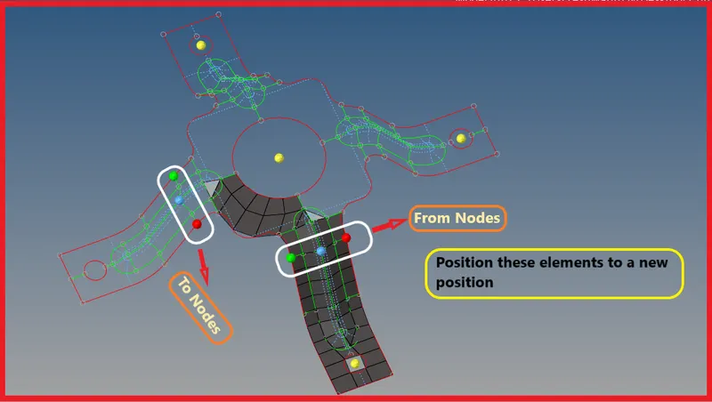
| Figure 83-Positioning the Elements to a New Position. |

| Figure 84-Position Tool Panel. |
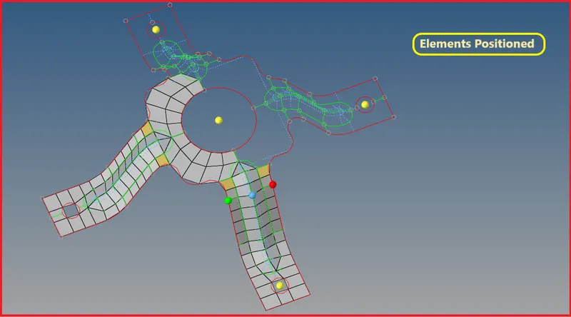
| Figure 85-Elements Positioned to a New Position. |
- Now reflect these elements to the other side using reflect from the tool panel.
- To Reflect,Go to Tool >> Reflect >> Elements >> Duplicate >> Define Appropriate Axis >> Base Point >> Reflect.

| Figure 86-Tool Panel. |
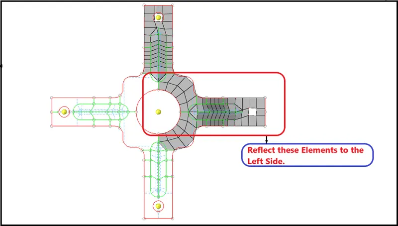
| Figure 87-Reflect the right side elements on the left side. |
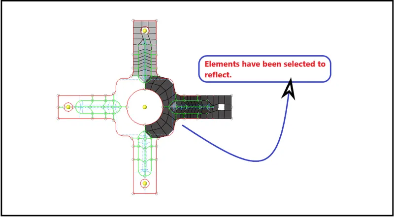
| Figure 88-Elements have been selected to reflect. |

| Figure 89-Reflect Tool. |
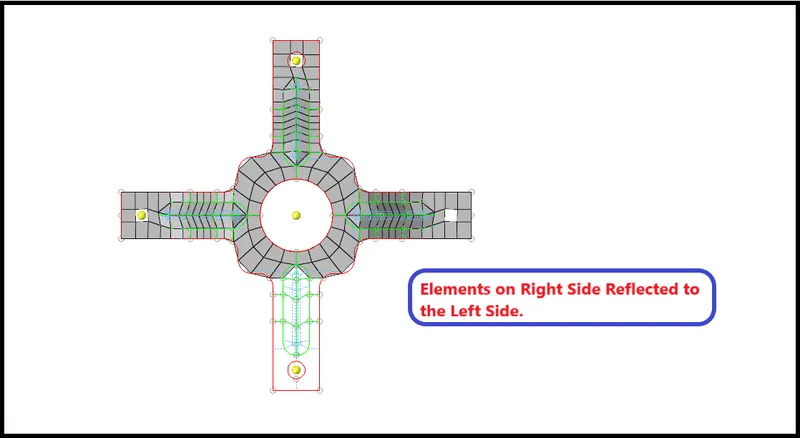
| Figure 90-Elements on Right Side Reflected the Left Side. |
- Now again position the elements which are on the top side to the bottom side.
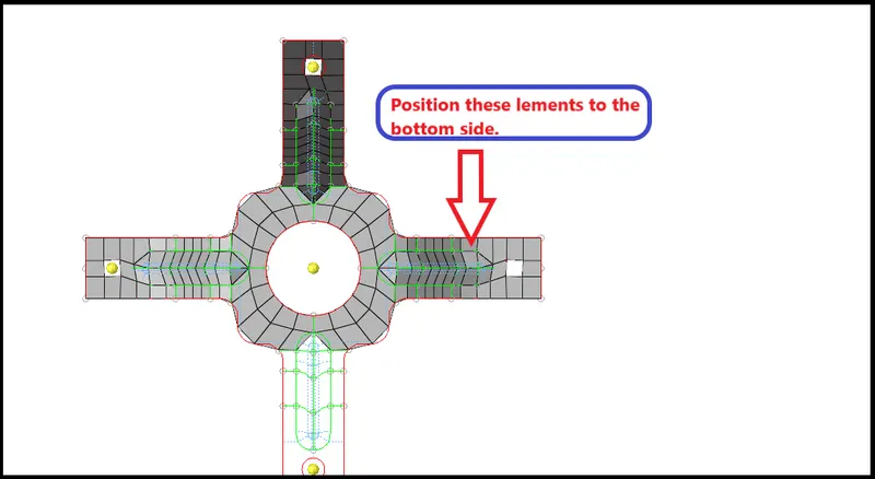
| Figure 91-Position the elements from the top side to the bottom side. |
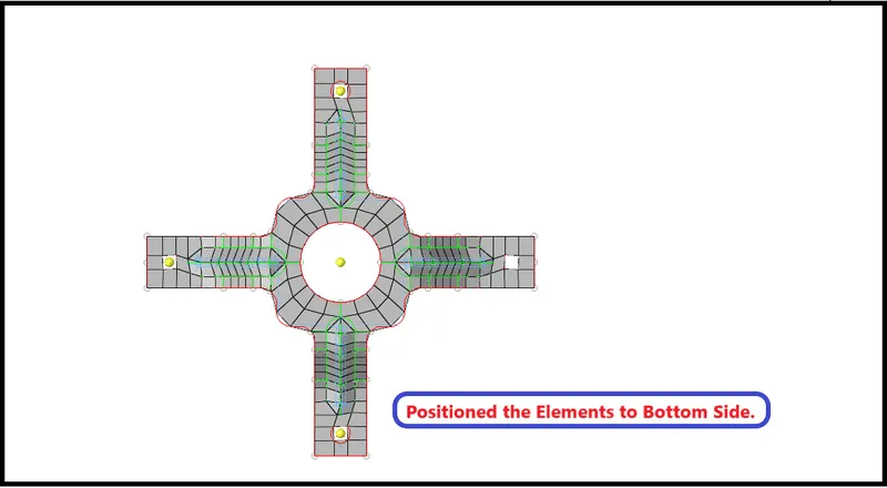
| Figure 92-Positioned the Elements to Bottom Side. |
- Now check for the connectivity, Whether all the elements have been equivalenced, If not Equivalence them.
- To check for the connectivity,Go to Tool >> Edges >> Elements >> Preview Equivalence >> Equivalence.

| Figure 93-Edges Panel. |
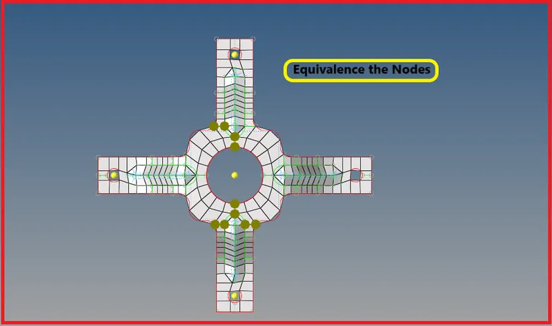
| Figure 94-Nodes that are not Equivalenced. |
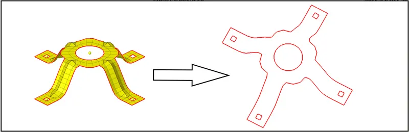
| Figure 95-A well connectivity has been established. |
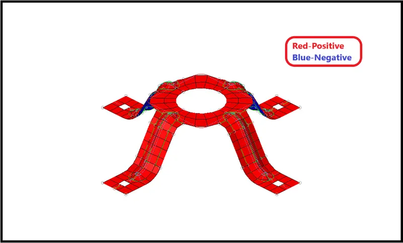
| Figure 96-Checks for Normals. |
- Now Switch to the 2D Detailed Element Representation and check, Whether the thickness has been assigned to the component or not.
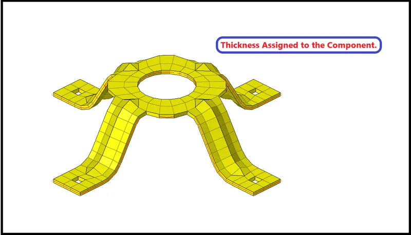
| Figure 97-Thickness Assigned to the Component. |
Final CAD Model Image -
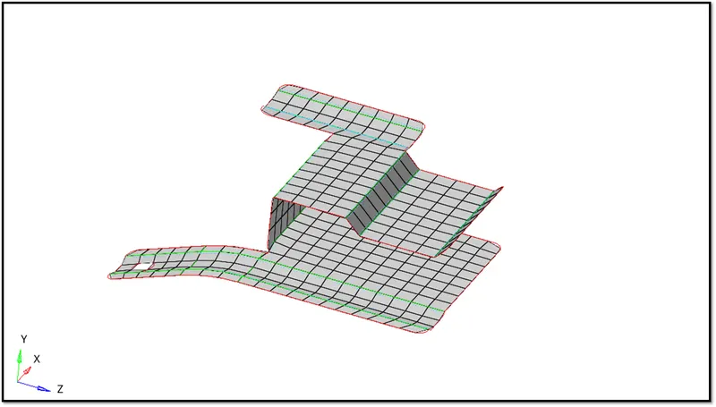
| Figure 98-Model_1 |
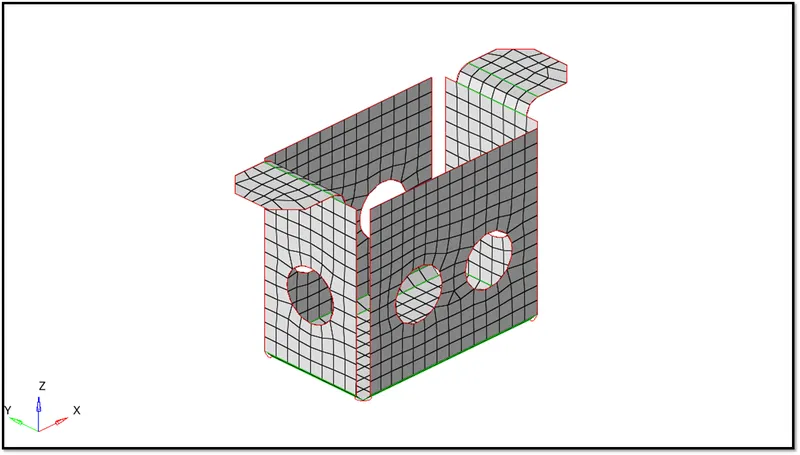
| Figure 99-Model_2 |
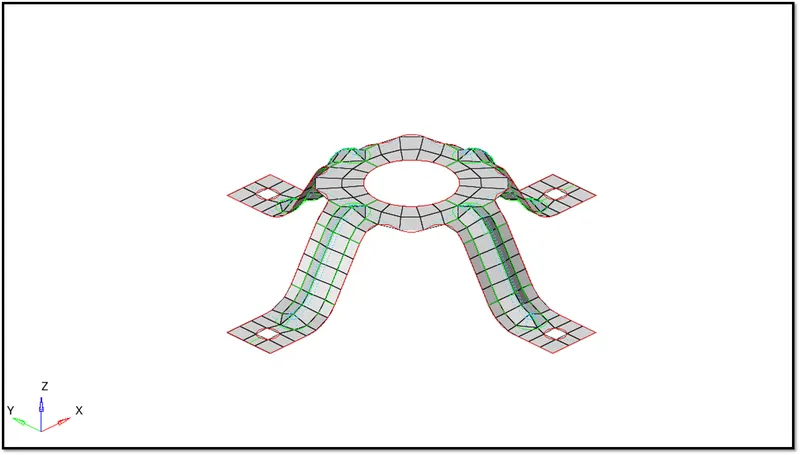
| Figure 100-Model_3 |
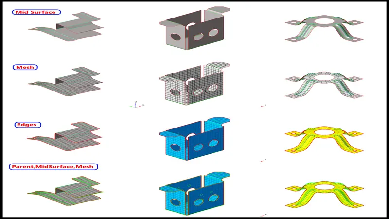
| Figure 101-Final CAD Model Image. |
Result -
- Mid Surface has been Extracted for all three models.
- Performed Geometric Clean Up on all three Models.
- Performed 2D Meshing for all three Models according to the given Quality Criteria.
- Assigned Thickness to all three Models.
Learning Outcome -
- In this 2D Meshing Challenge, I relearned and enhanced the things like
- Extracting the Mid Surface.
- Performing Geometric Clean Up on Parent and Mid Surface.
- 2D Meshing according to the given Quality Criteria.
- Maintaining the Element Quality.
- Assigning Thickness to the Components.