Assignment 1
1. Explore the GUI of GT SUITE and list down modules available with brief description. (15 marks)
GT-Suite includes some modules. I list down each module to the following.
| Engine Performance and Acoustics | This module includes some objects which are used for calulating engine perfomance and acoustics. The categories which this module include are General Engine, Diesel Engine, SI Engine Specifics, Turbocharging, Cylinder Pressure Analysis, Basic Exhaust After treatment, Acoustics, Mean-Value and Real-TIme, Two-Stroke Engines and Dyno and Vehicle Loading. |
| Exhaust Aftertreatment | This module only includes some objects regarding for Exhaust Aftertretment. |
| Cooling Systems and Thermal Management | This module includes some objects which are used for calulating cooling systems and thermal management. The categories where this module included are General Flow, Mapped Engines, Heat Exchangers, Pumps, Fans, Thermostats, General Thermal Analysis, Engine Structure Thermal Analysis. |
| Air Conditioning/Waste Heat Recovery | This module includes some objects which are used for calulating air conditioning and waste heat recovery. The categories where this module included are General Flow, General thermal analysis, Air Conditioning, Waste Heat Recovery and Controls. |
| Fuel Injection | This module includes some objects which are used for calulating fuel injection. The categories where this module are included are General Flow, General Mechanics, Detailed Injector, Injector On/Off Signal Generation, Detailed High Pressure Pump, Detailed Valve/Component Models, Controls, Simple Valve Actuation, Detailed Valve Actuation, Pump Line Nozzle Systems and General Mechanics. |
| Hydraulics and Pneumatics | This module includes some objects which are used for calulating parameters for Hydraulics and Pneumatics. The categories which this module are included are General Flow, Detailed Valve/Componet Models, Simple Valves Based On Supplier Data Sheets, Fluid Power Cylinders, Controls, Simple Valve Actuation, Detailed Valve Actuation, General Mechanics. |
| Lubrication Circuits | This module includes some objects which are used for calulating parameters for Lubrication. The categories where this module are included are General Flow Network, Predictive Bearing Model, Automatic Bearing Loads, Mean Value Bearing, Pumps, Predictive Pump Modeling, Detailed Valves Based On Geometry, Simple Valves Based On Supplier Data Sheets, Custom Oil Properties. |
| Vehicle and HEV Fuel Economy & Performance | This module includes some objects which are used for calulating parameters regarding for Vhecle and HEV Fuel Economy and Performance. The categories where this module are included are Vehicle Dynamics, Vehicle Controls, Hybrid and Electric Vehicles, Vehicle/HEV Controls and General Control. |
| Transmission and Shift Quality | This module includes some objects which are used for calulating parameters regarding for Transmission. The categories where this module are included are Transmission Hydraulics and Mechanics, Torsional Dynamics and Vehicle dynamics. |
| Cranktrain and Crankshaft Dynamics | This module includes some objects which are used for calulating parameters regarding for Cranktrain. The categories where this module are included Rigid Crank Dynamnics, Torsional Analysis, Bending Analysis, Block Vibration, FE Stress Recovery and General Mechanics. |
| ValveTrain Kinematics and Dynamics | This module includes some objects which are used for calulating parameters regarding for ValveTrain. The categories where this module are included are General Kinematics, Valvetrain Kinematics, Valvetrain Kinematics, Valvetrain Dynamics, Camshaft and General Mechanics. |
| Timing and Front End Drive Systems | This module includes some objects which are used for calulating parameters regarding for Drive Systems. The categories where this module are included are Helical or Spur Gear, Roller Chain, Silent Chain, Accessory Belt and Timing Belt. |
2. Locate following settings:
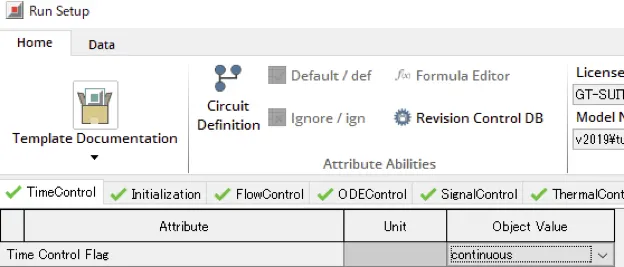
- Time control flag (5 Marks)
It is in TimeControl tab of the Run Setup. The place is shown in the Figure 2.1.
Figure 2.1 the position of Time control flag
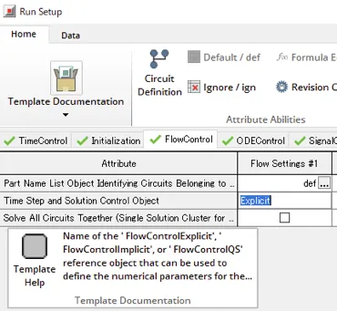
- Time step and solution control (5 Marks)
It is in FlowControl tab of the Run Setup. The place is shown in the Figure 2.2.
Figure 2.2 the position of Time step and solution control
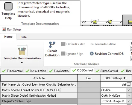
- Integrator/Solver type (5 Marks)
It is in ODEControl tab of the Run Setup. The place is shown in the Figure 2.3.
Figure 2.3 the position of Integrator/Solver type
3. Explore intercooler tutorial and note down all settings of:
- Run setup (5 Marks)
- Advanced setup (5 Marks)
- Plot setup (5 Marks)
- Output setup (5 Marks)
Intercooler tutorial has the following settings.
| Setup | Tab | Attribute | Unit | Object Value | |
| Run | Time Control Flag | FALSE | Maximum Simulation Duration (Cycles) | continuous | |
| FALSE | Minimum Simulation Duration (Cycles) | ||||
| TRUE | Maximum Simulation Duration (Time) | ign | |||
| FALSE | Minimum Simulation Duration (Time) | s | 0.5 | ||
| Automatic Shut-Off When Steady-State | s | ign | |||
| Main Driver (Defines Periodic Frequency) | on | ||||
| TRUE | Automatic | ||||
| FALSE | Part Name | ||||
| FALSE | Reference Object | ||||
| Improved Solution Sequence for Multi-Circuit Models | off | ||||
| Initialization | Initialization State | user_imposed | |||
| User Imposed Methods | |||||
| TRUE | Part Attributes | ||||
| FALSE | RLTs from Output File | ||||
| FALSE | Filename (.gdx or .gdt) for RLT Initialization | ||||
| FALSE | Case Number for RLT Initialization | ||||
| FlowControl | Part Name List Object Identifying Circuits Belonging to Column | def | |||
| Time Step and Solution Control Object | Explicit | ||||
| Solve All Circuits Together (Single Solution Cluster for the Column) | off | ||||
| ODEControl | Part Name List Object Identifying Circuits Belonging to Column | def | |||
| Matrix Sparse Format Solver (BETA for CSR) | Skyline | ||||
| Matrix (Node Order) Optimization Method | Cuthill-McKee | ||||
| Integrator/Solver Type | Explicit-Runge-Kutta | ||||
| Time Step and Solution Control Object | Explicit-def | ||||
| Time Step Output Frequency | def | ||||
| Solve All Circuits Together (Single Solution Cluster for the Column) | on | ||||
| Displacement SS Tolerance for Auto Shut-Off | ign | ||||
| Velocity Steady-State Tolerance for Auto Shut-Off | ign | ||||
| Torque Imbalance Tolerance for Auto Shut-Off | def | ||||
| Consecutive Cycles/RLT Update Intervals for Steady-State | 1 | ||||
| Modal Analysis Property Object | ign | ||||
| Matrix Inversion Scheme (electrical sol. only) | SVD | ||||
| SignalControl | Enhanced Controls Timestepping - BETA (Contact GT support) | ||||
| FALSE | Part Name List Object Identifying Circuits Belonging to Column | def | |||
| FALSE | TimeStep Size | use_physical_connected | |||
| FALSE | Fixed Time Step Size | s | ign | ||
| ThermalControl | Thermal Wall Calculation Interval | s | def | ||
| Thermal Wall Steady-State Tolerance for Auto Shut-off | K/s | ign | |||
| Convergence Threshold for Flow Solver Skipping | fraction | ign | |||
| Number of Thermal Calculation Intervals to Skip Flow Solver | ign | ||||
| Periods at Initial Wall Temperature (WallTempSolver only) | def | ||||
| ConvergenceRLT | RLT Convergence Checks for Steady-State Auto Shut-off | ||||
| FALSE | RLT Variable | ||||
| FALSE | Activate Convergence Criteria | on | |||
| FALSE | Type of Steady State Criterion | RLT_interval | |||
| FALSE | Target Value of RLT Variable | ign | |||
| FALSE | Multiplier to RLT Value (Prior to Comparing to Target) | def | |||
| FALSE | Type of Steady State Tolerance | fractional | |||
| FALSE | Steady State Tolerance | ||||
| FALSE | Consecutive Cycles/RLT Update Intervals for Steady-State | def | |||
| Advance | General | FALSE | Import Parameter Data from External File? | ||
| Fixed Time Step Size (Overrides Flow and Mech Step) | s | ign | |||
| Initial Seed for Random Number Generation | def | ||||
| Convergence Exclusion Part List | ign | ||||
| Flow | Bend Loss Table | ign | |||
| Gibbs Equilibrium Calculation | off | ||||
| Adjust Nitrogen Molecular Weight to Compensate For Argon | on | ||||
| Air Object for Ref Stoich AF Ratio (or value for multi-fuel models) | def | ||||
| Dump 2nd law output? | off | ||||
| Dead State for 2nd Law Output | ign | ||||
| More Conservative Timestep Limit for Single-Volume Pipes | off | ||||
| More Conservative Timestep Limit for Flowsplits with Small Holes | off | ||||
| More Conservative Timestep Limit for Absorbing Flowsplits (Wool) | off | ||||
| Stable Flow Through Cylinders at Large Timesteps | |||||
| TRUE | Improved Solution for Large Flow Through Cylinders | off | |||
| FALSE | More Conservative Timestep Limit for Large Flow Through Cylinders | on | |||
| FALSE | Small Mass Protection in Cylinder | off | |||
| Cylinder Efficiency Analysis | off | ||||
| Improved Stagnation Condition Calculation in Turbomachinery Templates | on | ||||
| Alternative Calculation of Laminar Flow Losses in FMTs | off | ||||
| Alternative Orifice Calibration Method for FlowPDropSimple Objects | on | ||||
| Improved Calculation of Default Pressure Loss Coefficient for Diffusers | on | ||||
| Improved Implicit Solver Global Residual Definition | on | ||||
| Improved FluidRefrigerant Properties Lookup | on | ||||
| Improved Scavenging Profiles Lookup | on | ||||
| PipeTable Treated as a Solver Compound | off | ||||
| Use Min/Max Temperature Limits when Evaluating Properties | off | ||||
| Use Faster Momentum Calculation | off | ||||
| Mass Fraction Threshold to avoid Underflow Slowdown | ign | ||||
| Transport Properties for Species without Data | always air | ||||
| Clausius-Clapeyron Based Saturation Curve Calculation for Water | off | ||||
| Alternate Solver for Improved Stability (Explicit Only) | off | ||||
| Alternate Implicit Solver for Faster Convergence of Multi-Fluid Flows | off | ||||
| Automatic Detection of IVC for Cylinder RLT Determination | off | ||||
| Mechanics | Gravitational Acceleration Vector | m/s^2 | ign | ||
| Restart | FALSE | Start Storing Data from Cycle or Time | def | ||
| FALSE | Restart File Storage Interval (Cycle or Time) | ||||
| FALSE | Number of Restart Files to Keep for Each Case | def | |||
| FALSE | Always Store Data at Each Case End | on | |||
| FALSE | Always Store Data at Simulation End | on | |||
| FALSE | Keep Restart Files When a Case Ends Normally | on | |||
| VersionChange | General | ||||
| Version Setting for Non-itemized Changes | v2019 | ||||
| Detailed Evolution Flags (GT Use Only) | ign | ||||
| Acoustics | |||||
| Improved Linear Analysis Calculation for Non-default Orifices Connected to Boundary Condition | on | ||||
| Improved Linear Analysis Calculation for PipeRoundFlexWall | on | ||||
| Corrected Resistance for Absorbing Flowsplits (Wool) | on | ||||
| Improved Steady Thermal Solution for Absorbing Flowsplits (Wool) | on | ||||
| Compressors, Turbines, Pumps | |||||
| Fix Turbine Template RLTs with more than 1 Inlet | on | ||||
| Improved Enthalpy Calculation for Pumps | on | ||||
| Improved Friction Calculation for Internal Turbine Wastegate | on | ||||
| Turbine/Compressor: Improved Temperature of Exiting Gas | on | ||||
| Controls | |||||
| Improved Initialization of Controls Components | v2019 | ||||
| Improved 'time' Variable for Controls Components Equations | on | ||||
| Fix Model Convergence Check if Controller Deactivation is Used | on | ||||
| Corrected Initialization for PIDController | on | ||||
| Corrected Indices for Product and PIDController Templates | on | ||||
| Corrected SignalGenPhaseFiringOrder for Main Driver with Non-Zero Start of Cycle | off | ||||
| Cranktrain | |||||
| Corrected Calculation of Avg. Engine Speed (when actuated) | on | ||||
| Improved Integration of EngineCrankTrain RLT's | on | ||||
| Improved Integration of EngineCrankTrain Cycle-Averaged Sensors | v2019 | ||||
| Corrected Actuation of Oil and Coolant Temperatures for EngFrictionSR | on | ||||
| Cylinders | |||||
| Fix Cylinder Heat Transfer Rate and CrankTrain Inst. Heat Rejection Rate Sensors (RT Solver) | on | ||||
| Corrected Valve Heat Transfer for Cylinder Pressure Analysis | on | ||||
| Improved EVO Detection for Cylinder Heat Transfer | on | ||||
| Fix EngCylinder Heat Transfer RLT | on | ||||
| Fix Maximum Temperature RLTs | on | ||||
| Correct Improper Disabling of In-Cylinder Radiation | on | ||||
| Corrected GTI_Cylinder Real Gas Option | on | ||||
| Improvements to EngCylFlame for Non-SITurb Use | on | ||||
| Corrected Knock Induction Time Integral RLT for SITurb | on | ||||
| Include Fresh H2O and CO2 in the Diluent Concentration for Kinetics-Fit-Gasoline Knock Model | on | ||||
| Fix Cylinder Slaving | v2019 | ||||
| Allow Actuation of Combustion Attributes Until Start of Combustion | v2019 | ||||
| Correction to non-standard MEP RLTs | v2019 | ||||
| Corrected Cylinder Emissions RLTs When Using Emissions Map | on | ||||
| Piston Pin Offset Correction | v2017 | ||||
| Corrected Shifting and Smoothing of Pressure for Multi-cycle TPA | on | ||||
| Enable Knock Calculations at Start of Cycle | v2018_b2 | ||||
| Improved Vol. Eff. for Cylinders in 2+4 Stroke Mode | on | ||||
| Improved Normalization of Combustion Quantities | v2018 | ||||
| Fix CCV calculations for the FVV model | off | ||||
| Corrected FluidMixture handling in EngCylInit for non Fuel Species | on | ||||
| Fixed Initialization of some Cylinder Heat Transfer Models | off | ||||
| Allow Radiation Heat Transfer for SI Combustion | on | ||||
| Fix Dynamic Compression Ratio RLT for Piston Position Actuation | on | ||||
| Fix Calculations for EngCylCombDualFuel | v2017 | ||||
| Rebalance Species Mass Fractions when Using Soot Model | on | ||||
| Fix PreChamber Calculations | v2019 | ||||
| Data | |||||
| Corrected XYZPoints Behavior when Upper/Lower Boundaries Intersect | v2018 | ||||
| Corrected Non-Default Units for Excel Array Data | on | ||||
| Improved Truncation of Data in XYTable | on | ||||
| Improved Moving Average Algorithm | on | ||||
| Use Correct Driver for ProfileAngles when in Load Mode | off | ||||
| Correct ProfilePeriod Lookup when TimeControl is 'Continuous' | off | ||||
| Corrected Conversion of Non-Defaults Units in XYZFunction | on | ||||
| Corrected RLTDependenceMulti Lookup | on | ||||
| Corrected Conversion of Non-Default Units in RLTDependenceMulti | on | ||||
| Friction & Tribology | |||||
| Composite Surface Roughness Calculation Method | Old | ||||
| Corrected Mean Surface for Roughness Parameter Extraction (Tomanik/McCool) | off | ||||
| Corrected Effect of Lubricated Pad Position on Piston Friction | on | ||||
| Corrected Impedance Maps for Side-pressurized Bearing | on | ||||
| Electrical | |||||
| Improved Initialization of Electromagnetics Components | on | ||||
| Corrected Stator Motion when Incoming | on | ||||
| Improved Explicit Electromagnetics Solution | on | ||||
| Fix Fuel Cell Calculations | v2019 | ||||
| Flow, Other | |||||
| Improved Solution for EndEnvironmentTPA | v2018 | ||||
| FlowPDropTableRef and FlowPDropLossCoef: Improved Handling of Low Flow Data | on | ||||
| Fix Altitude Correction with Previous Case Initialization | on | ||||
| Improved FluidReservoir Solution if Liquid/Gas Interface Crosses a Port | v2019 | ||||
| Improved Tank3D Solution if Liquid/Gas Interface Crosses a Port | on | ||||
| Fluid Properties | |||||
| Improved Evaluation of Fluid Properties | v2018 | ||||
| Improved Combustion Calculations | on | ||||
| Improved Calculation of Latent Heat when Condensing Using "on_wall" | on | ||||
| Improved Run-time Evaluation of Fluid Properties | on | ||||
| Improved Enthalpy for FluidNASA-LiqGas below Minimum Temperature of Fitting Range | on | ||||
| Heat Exchangers | |||||
| Corrected Heat Transfer Area When Scaling MatrixHA | on | ||||
| Corrected Volume Calculation for Multi-Pass HXs | on | ||||
| Improved Pressure Drop Correlation for Refrigerant HXs | on | ||||
| Improved HxNuMap(Refrig) Correlation | on | ||||
| Improved FlowPDrop Regression with Humid Air Condensation | on | ||||
| Improved HxNuMap* Preprocessing | v2018 | ||||
| Corrected Louver-Fin Correlation | on | ||||
| Improved Results for HxGeomGeneral with Single Volume | on | ||||
| Hydraulic | |||||
| Improved Jet Force Calculation for Spools | on | ||||
| Corrected Maximum Area for SpoolNotchGeometry(MH) | on | ||||
| Corrected Non-Linear Spring for FluidPistonAndSpring | on | ||||
| Injectors | |||||
| Improved Solution for GT-POWER Injectors | v2019 | ||||
| Improved Handling of Transient Injector Quantities | v2016_b2 | ||||
| Correct Calculation of Global CA for valves and injectors | on | ||||
| Improved Solution when Injecting into Burner | v2019 | ||||
| Miscellaneous | |||||
| Corrected Explicit Euler ODE Integration | on | ||||
| Corrected End of Cycle Detection for ODE Circuits using ISS | on | ||||
| Alternative Maximum Timestep for Models Without Thermal Parts | off | ||||
| Remove 0.0008 sec Cylinder Timestep Restriction | on | ||||
| Parallel Processing Fixes | v2016 | ||||
| Improved Driver Angle Sync. for Multi-Circuits Models using ISS | on | ||||
| Improved Consistency of Part Order Read by Solver | off | ||||
| Improved Unit Handling for Arrays | off | ||||
| Improved Unit Handling for Temperature Shift Attributes | on | ||||
| Orifices, Valves, Throttles | |||||
| Improved Flow Calculation in Valves, Throttles | v72_b2 | ||||
| Update Valve Lift Profile at Local Start of Cycle | on | ||||
| Improved Logic for Valve Type Detection | on | ||||
| Corrected Valve RLTs | V2018 | ||||
| Enable Part Override for Valve Reference Diameter | on | ||||
| Allocate Valve Lift Profiles per Parts | on | ||||
| Improved Solution for Orifices with Thickness | v72 | ||||
| Apply Laminar Face Friction Multiplier in Orifices | on | ||||
| Improved Discharge Coefficient Calculation for Contractions | on | ||||
| Corrected Flow Area for Multiple Holes in Orifice (Implicit Solver) | on | ||||
| Allow Valve*Conn to Use Driver from Adjacent EngCrankcase Part | off | ||||
| Corrected Area for Select Valves in Hydraulics/Pneumatics (Simple) Library | on | ||||
| Corrected XYTable Usage for CD in ValveActuLiftAreaCon | on | ||||
| Pipes, FlowSplits | |||||
| Improved Solution for FlowSplitTRight | on | ||||
| Use Geometric Area for Pipe and FlowSplit Friction Loss | on | ||||
| Fix Non-Circular Pipe improved_friction_bend Flow Loss Model | on | ||||
| Enable transient profile in puddle fuel fraction in port | on | ||||
| Fix for switching condense/evaporate option case by case | on | ||||
| Thermal | |||||
| Always Model Liner Inlay as Separate FE Structure | on | ||||
| Improved Lookup Accuracy for F.E. Cylinder Structure Gas Boundary Conditions | on | ||||
| Improved Laminar Heat Transfer Model | on | ||||
| Improved Thermal-Flow Solution Method | on | ||||
| Corrected Conduction for PipeCrossSection and PipeRectangle | on | ||||
| Improved Thermal Solution For FlowSplitNode | on | ||||
| Fix EngCylTWallSoln Time Step for Multiple ODE Circuits | on | ||||
| Fix Effective Gas Temperature for Calculated Wall Temperature | on | ||||
| Fix Port to Head Conduction Heat Trans. Area | off | ||||
| Improved Thermal Wool Solution for Continuous Simulations | on | ||||
| Fix Flowsplit and FluidMachineChamber Heat Transfer Coefficient If Port Area is 0 | on | ||||
| Fix RLT for Piston Skirt Net Heat Transfer Rate | on | ||||
| Fix def Piston/Bore Area Ratio for Custom FE Cylinder | on | ||||
| Improved Execution Sequence for Thermal Solution | on | ||||
| Corrected Thermocouple Solution When the Same Thermocouple is Used in Multiple Parts | on | ||||
| Corrected Expansion Diameter Calculation in FluidMachineChamber | on | ||||
| Corrected Thermal Solution Initialization | on | ||||
| Fix External HTC behavior in Temperature parts | on | ||||
| Corrected Thermocouple Temperature Initialization | on | ||||
| Uncategorized | |||||
| Enable Mass & Energy Balance Correction in CFDFieldImport | on | ||||
| Fix Detection of Refrigerant Circuits | on | ||||
| Paths | TRUE | Paths Specified Explicitly Below | |||
| FALSE | Paths Array Reference Object | ||||
| MiscFiles | Additional Files to Send (Distributed Runs) | ign | |||
| File Type | ASCII | ||||
| Output | Data_Storage | RLT (Result) Data Storage Settings | |||
| RLT Calculation Interval (Continuous Circuits) | s | 0.05 | |||
| TRUE | Store Case RLT Results? | ||||
| FALSE | Storage Level for All Parts NOT Listed Below | All | |||
| FALSE | Storage Level for "Exception" Parts Listed Below | All | |||
| FALSE | Exception Parts List | ign | |||
| FALSE | Store Time RLT Results? | ||||
| List of RLT's to store (ALWAYS) | ign | ||||
| Plots and Table Data Storage Settings | |||||
| Time Shift on X-Axis for EntireRun and TimeRLT Plots | s | ign | |||
| Data Suppression for EntireRun Plots and TimeRLTs: Threshold Time | s | ign | |||
| Suppress Storage of Instantaneous Plots | off | ||||
| Suppress Storage of Pre-Processed Plots | off | ||||
| Suppress Storage of Tables (except EndOfRun Tables) | off | ||||
| General | |||||
| Thinning Method for Limiting Large Arrays to Maximum Point Limit | Automatic | ||||
| Do Not Show Warning Dialog for Large Result Sets | off | ||||
| General | Legend for Plot Header (OBSOLETE) | def | |||
| Timestep Plot | on | ||||
| Store RLTs for Tracking Memory (RAM) Consumption | off | ||||
| Vehicle Energy Use and Loss Plots | off | ||||
| Suppress .brf file (file not available in future) | on | ||||
| GT-POST_Setup | Setup for RLTs (These settings can be changed in GT-POST) | ||||
| X-Axis RLT for Case Sweep Plots | def | ||||
| X-Axis RLT for Time RLT Plots (only used in Periodic Circuits) | time | ||||
| Automatically Compare RLT Results with External Data | |||||
| FALSE | External Data File for Comparison | ||||
| FALSE | Worksheet Name for Excel File | def | |||
| FALSE | Associated Formatting File | ||||
| Plot Formatting File | def | ||||
| Add Companion GU to this Model for Automatic Report Creation | |||||
| FALSE | Companion GU File | ign | |||
| Flow | Data Storage | ||||
| FALSE | Number of Flow Animation Points | ign | |||
| FALSE | Store Microphone Data | Automatic | |||
| FALSE | Order/Mode Storage Object for Acoustic/Frequency Analysis | ign | |||
| FALSE | Number of Order Storage Points | 720 | |||
| Maximum Harmonics Stored for Acoustic/Frequency Analysis | def | ||||
| Miscellaneous Flow Options | |||||
| Calculate Water Saturation (Dew) Temperature RLT | LastRLTInterval | ||||
| Store Flow and Engine Results Summary in .out File? | no | ||||
| ODE-Mech | ODE Solver Numerics Results | off | |||
| Mechanical Model 2-D Plot and Animation Object | ign | ||||
| Kinematic Model 2-D Plot and Animation Object | ign | ||||
| Frequency Analysis 2-D Plot and Animation Object | ign | ||||
| Mechanical Model 3-D Plot and Animation Object | ign | ||||
| ScoreboardRLTs | Cranktrain | ||||
| Cylinder | |||||
| Turbo | |||||
| Lubrication | |||||
| Detailed Injector | |||||
| Vehicle | |||||
| Heat Exchanger | |||||
| Refrigerant Flow Machinery | |||||
| Battery | |||||
| EndOfRunTables | EndOfRunTables are designed for displaying RLTs from single or mlutiple test cases vs. Model Configurations | ||||
| Location of Model Configuration Sweep | Case_Setup | ||||
| Parameter Defining Configurations | ign | ||||
| Results for each Model Configuration in Column or Row | Column | ||||
| EndOfRunTable Object 1 | ign | ||||
| EndOfRunTable Object 2 | ign | ||||
| EndOfRunTable Object 3 | ign | ||||
| EndOfRunTable Object 4 | ign | ||||
| EndOfRunTable Object 5 | ign | ||||
| Plot | Default Values | Max Plot Points | 1500 | ||
| X-Axis | Automatic | ||||
| Plot Range | Automatic | ||||
| Sampling Type | Timestep | ||||
| Sampling Interval | 1 | ||||
| 0.0 time reference for X=Time when LastCycle | FALSE | ||||
| Location | 0.5 | ||||
| Interpolation Option | use_nearrest_volume | ||||
4. Problem: (50 Marks)
Given
- Diameter of cooler inlet and outlet pipe= 50 mm
- Length of the CAC= 1000 mm
- Inlet mass flow rate = 1200 kg/ h at 100 degC
- Outlet pressure 2 bar at 30 deg C
- Calculate the total heat transfer at Charge air cooler (CAC)
- Calculate pressure drop across CAC
(Setting simulation condition)
I used intercooler-final.gtm which are provided in GT tutorial as base model.
The model map is shown in the following figure 4.1.
Figure 4.1 Map of intercooler-final.gtm

First, I set given condition to the model.
・Diameter of cooler inlet and outlet pipe= 50 mm
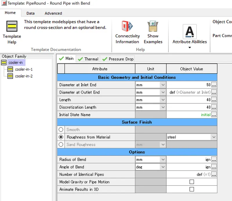
I changed setting of some objects which are cooler-in and cooler for diameter of cooler inlet and outlet pipe.
1. In the cooler-in, diameter at Inlet End is set to 50mm. Diameter at Outlet End is same setting as Inlet. So, it is set to def.
The settings are shown in the Figure 4.2.
Figure 4.2 Setting of cooler-in objects about diameter.
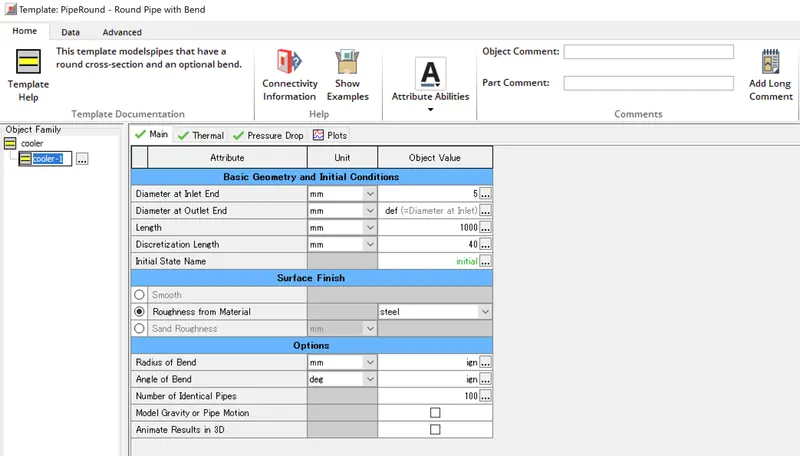
2. In the cooler, diameter at Inlet End is set to 5mm for modeling heat exhanger.
This object models a lot of pipe for heat exchanger. The setting is Number of Identical Pipes which is set to 100.
So, diameter at Inlet End means a diameter of a pipe. Diameter at Outlet End is same setting as Inlet. So, it is set to def.
The settings are shown in the Figure 4.3.
Figure 4.3 Setting of cooler object about diameter.
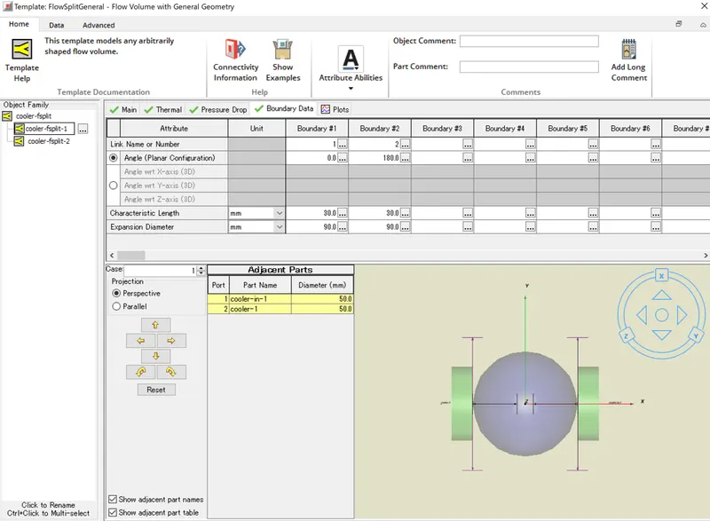
3. In the cooler-fsplit, I confirmed diameters of cooler inlet and outlet pipe.
In the boundary data tab, I checked adjacent part diameters are 50mm.
The settings are shown in the Figure 4.4.
Figure 4.4 Setting of cooler-fsplit objects about diameter.
・Length of the CAC= 1000 mm
I changed setting of cooler object . In the main tab, I set 1000mm to Length.
The settings are shown in the Figure 4.5.
Figure 4.5 Setting of cooler object about Length.
・Inlet mass flow rate = 1200 kg/ h at 100 degC
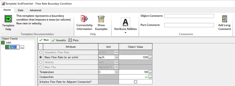
I changed setting of Inlet object.
In the main tab, I set 1200kg/h to Mass Flow Rate(or air scfm) and 100 ℃ to Temperature.
The settings are shown in the Figure 4.6.
Figure 4.6 Setting of Inlet object about Inlet mass flow rate.
・Outlet pressure 2 bar at 30 deg C
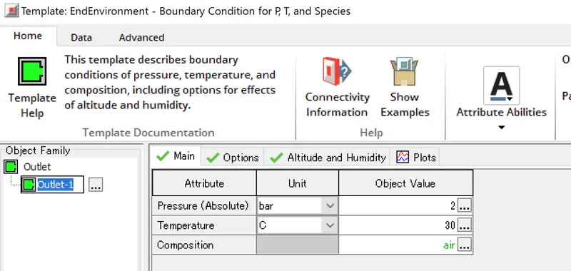
I changed setting of Outlet object.
In the main tab, I set 2 bar to Pressure(Absolute) and 30℃ to Temparature.
The settings are shown in the Figure 4.7.
Figure 4.7 Setting of Outlet object about Outlet pressure and temperature.
(Run simulation and confirm result)
After the settings, I ran the simulatiom and confirmed the result by using RLT contour map in the GT post.
・Calculate the total heat transfer at Charge air cooler (CAC)
I checked Average Convective Heat Transfer Rate of CAC by using RLT contour map.
The total heat transfer a Charge air cooler is 7.55kW. The result is shown in the Figure 4.8.
Figure 4.8 Result of the total heat transfer

・Calculate pressure drop across CAC
I checked Pressure drop by using RLT contour map.
The pressure drop is 0.482bar. The result is shown in the Figure 4.9.
Figure 4.9 Result of the pressure drop of CAC.

・Check result
In the result, I checked wheather the simulaiton is right or not by comfirming given condition parameter.
・Inlet mass flow rate = 1200 kg/ h at 100 degC
・Outlet pressure 2 bar at 30 deg C
I checked Average mass flow rate for checking Inlet mass flow rate by using RLT contour map.
The value is 1200 kg/h. So, the condition is OK. The result is shown in the Figure 4.10.
Figure 4.10 Result of the average mass flow rate

And I checked temperature for checking Inlet and Outlet temperature by using RLT contour map.
The values are 100℃ at Inlet and 30℃ at Outlet. So, the conditions are OK. The result is shown in the Figure 4.11.
Figure 4.11 Result of the temperature

Finaly, I checked pressure for checking Outlet pressure by using RLT contour map.
The value is 2 bar at Outlet. So, the condition is OK. The result is shown in the Figure 4.12.
Figure 4.12 Result of the pressure
