Assignment 1
AIM:
To carry out Geometry clean up, Extract mid surface and to do 2D meshing on mid surface of the following given Components:
1) Practice component.
2) Clip repair component.
3) Mounting Bracket.
OBJECTIVE:
To,
1) Clean the geometry.
2) Extract midsurface.
3) Clean midsurface geometry.
4) Ignore holes less than dia 5mm.
5) Create 2D mesh with target length 5mm, min:3.5mm, max:7mm.
6) And assign proper thickness by creating a generic property.
PROCEDURE:
A] PRACTICE MODEL:
1) First we have to open the given practice model which is in ".hm" file in Hyperworks
2) This above model has to be checked for geometry, that is if there are any "free edges" or "multiple surfaces" or "Unwanted extra surfaces" etc... these has to be cleaned up before extracting the mid surface of this component, these Geometrical errors can be found by changing "Geometry color mode" to "Mixed" and we also have to change the whole Geometry to "Wireframe Geometry", all the "Geometry errors" are recognised by "RED" lines and "yellow lines" as shown in the below snap.
Here if there is any geometric errors we have to goto: 'Geom' > 'Quick edit' > 'Toggle edge'
but here we don't see any Geometrical errors, so we can move to the next step, that is "MIDSURFACING"
3) To extract the "MIDSURFACE" of any component we have to do the following steps which is for "AUTO MESHING"
'Geom' > 'Midsurface' and then select the whole component and then hit 'Extract' button, now Midsurface will be created for the whole component, but here when we try to extract the "MIDSURFACE" of this practice model, BUT we didn't get the perfect midsurface of this model, the midsurface which we extracted is bit Distorted, so we have to extract Midsurface of this component "Manually", for this we have to follow the steps as shown below:
'Geom' > 'Surface edit' > 'offset' > 'click on the surface which needs to be offseted' > 'click on the surface block and select "DUPLICATE" to retain the original surface' > 'then hit "offset -1" so thet the surface gets offseted invard'. This is how " MANUAL MIDSURFACE" can be done if "AUTO MIDSURFACE" doesn't work.
Now the midsurface is created as shown below:
4) If this component is having holes which are of dia 5mm, they all are neglected, and these holes are filled by doing these steps:
'Geom' > 'Quickedit' > 'Fillersurface' , then click on the holes which needs to be filled and then 'toggle' those circles by doing 'Geom' > 'Quickedit' > 'toggle' , then click on the circles then this would be toggled.
5) After all these steps we have to "MESH" the whole midsurface, this can be efficiently done by splitting the surface to our requirement, this can be done by using the tools like 'split surf node' which splits the surface using 'two nodes' and 'split surf line' which splits the surface using 'node to line' , this tool can be found in 'Geom' > 'Quickedit'.
Now "2D-MESHING" is done by going to '2D' > 'Automesh', then start doing the mesh from the middle of the midsurface for better mesh continuity. And one by one all the surface should be Meshed separately.
Min element size:3.5mm, Max element size:7mm and Target size:5mm are all set in 'Tools' > 'Check elements' > 'Edit criteria', here we can set all the required standards required.
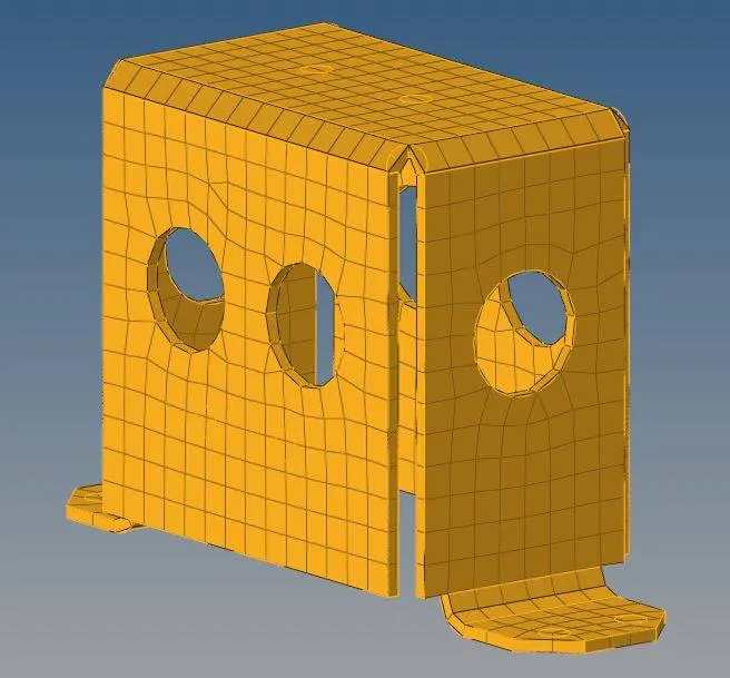
In the below figure, the whole midsurface has been meshed.
If the mesh created is not having proper mesh flow, we have to select only those elements and "re-mesh" them using "Automesh" in "2D" or we can use "Smooth" tool by going to 'Tool' > 'Smooth', click the elements seperately and then hit "Smooth", this will increase the mesh flow quality.
After meshing this whole midsurface, we have to check for Minimum size and Maximum size criteria, this can be done by 2 methods, they are:
a) 'Tools' > 'Check elements' > 'Click on the min size or max size', the failed element will be highlighted and this failed element can be be made right by changing the element size manually by using: 'Geom' > 'distance' or we can use F4 as short cut.
b) Goto '2D' > 'Quality index', here the failed element will be highlighted by another color, here use "Optimize element" and click on the failed element, the element will automatically adjust not to be failed. By doing this for each and every failed element, all the element can be made to follow the maximum size and minimum size criteria.
After all the quality checks, there will be a message in the bottom left corner indicating Zero elements failed.
6) Now we have to assign proper thickness "NEAR BROWSER", here we should first check the thickness of the given component by using "F4", then the final mesh for this 2mm thickness component is as shown below:
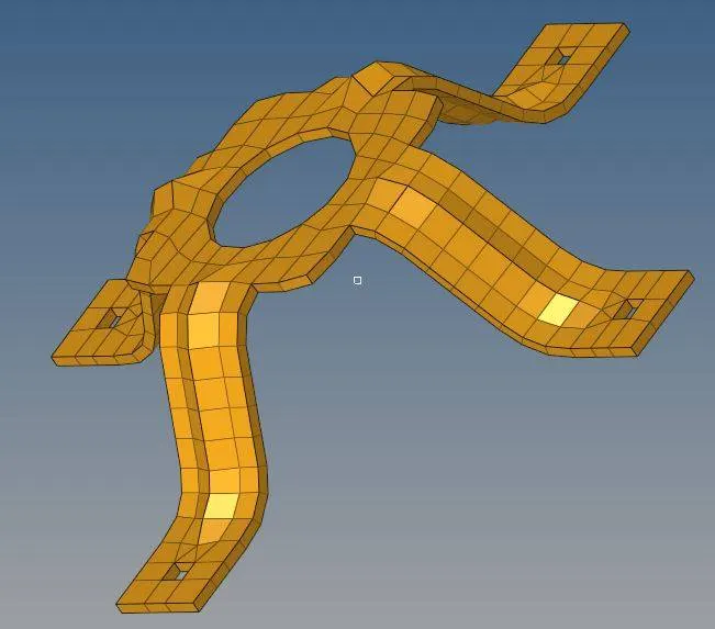
B] CLIP REPAIR:
Same methods and procedures are used to obtain "GEOMETRY CLEANUP", "TO EXTRACTING MIDSURFACE", "FOR 2D MESHING" AND "TO ASSIGN PROPER THICKNESS" as explained for the above "PRACTICE COMPONENT".
1) GIVEN MODEL:
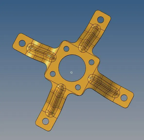
2) MODEL IN WIRE FRAME FOR ANY GEOMETRY CLEAN UP: "None found".
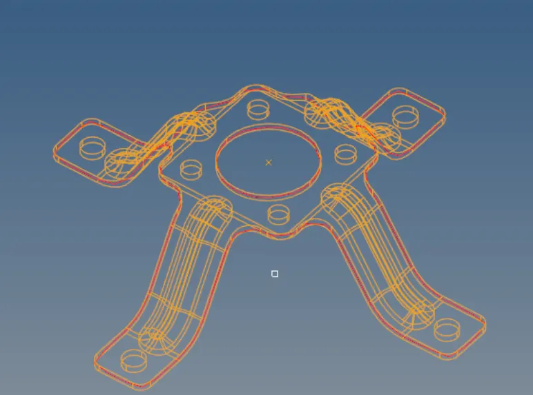
3) EXTRACTED MIDSURFACE: "Here holes below 5mm are removed for better mesh quality".
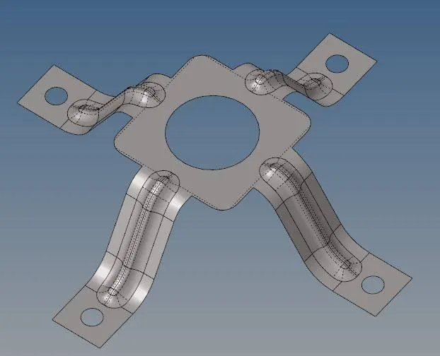
4) MESHED MIDSURFACE:

5) FINAL COMPONENT MESH: "After assigning Thickness in Properties"
C] MOUNTING BRACKET:
Same methods and procedures are used to obtain "GEOMETRY CLEANUP", "TO EXTRACTING MIDSURFACE", "FOR 2D MESHING" AND "TO ASSIGN PROPER THICKNESS" as explained for the above "PRACTICE COMPONENT".
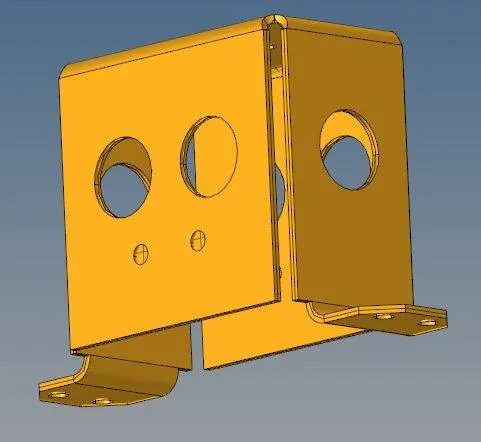
1) GIVEN MODEL:
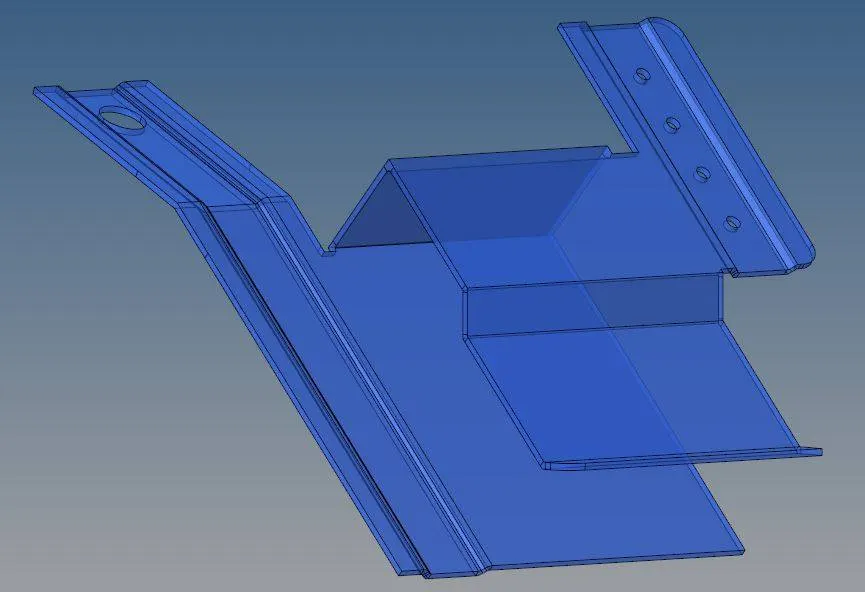
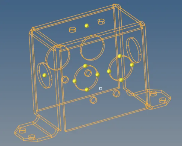
2) MODEL IN WIRE FRAME FOR ANY GEOMETRY CLEAN UP: " Many geometrical errors are found as shown below".
.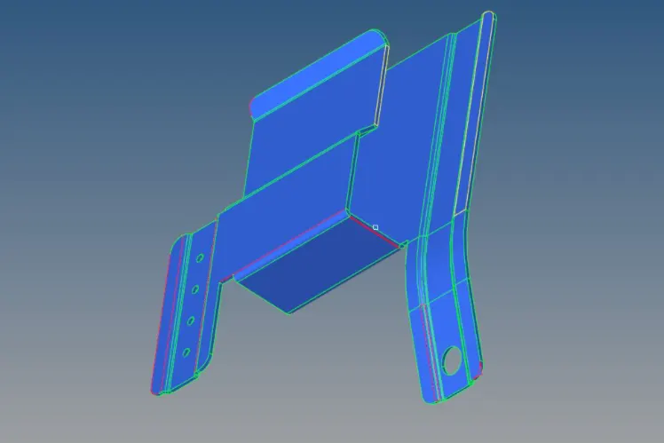
Now we have to clear all these errors and then extract " MIDSURFACE".
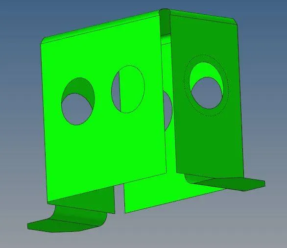
4) EXTRACTED MIDSURFACE: "Here holes below 5mm are removed for better mesh quality".
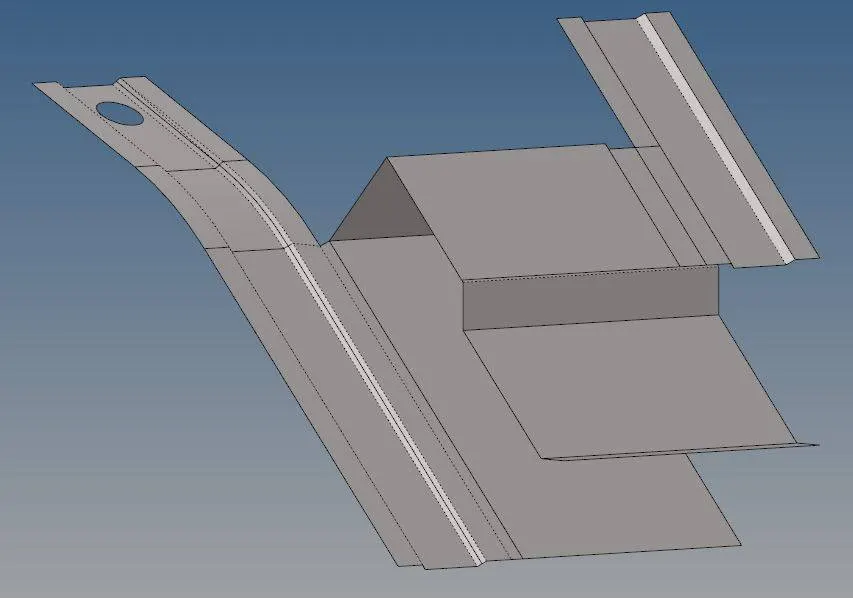
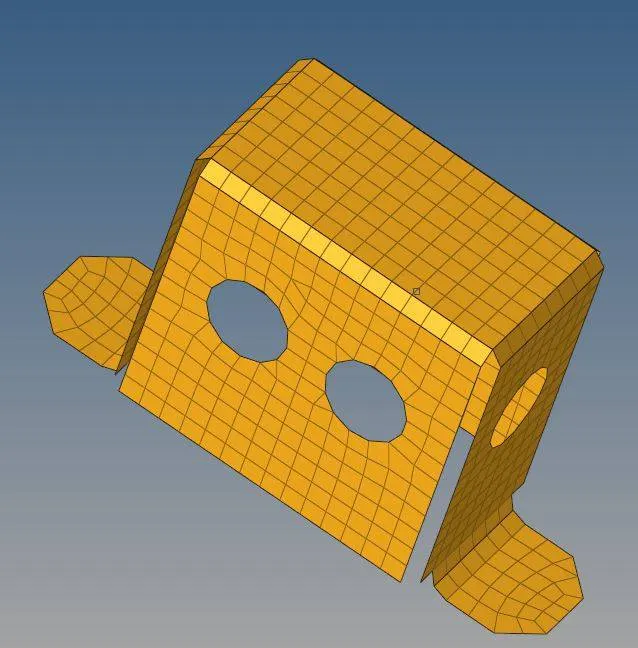
5) MESHED MIDSURFACE:
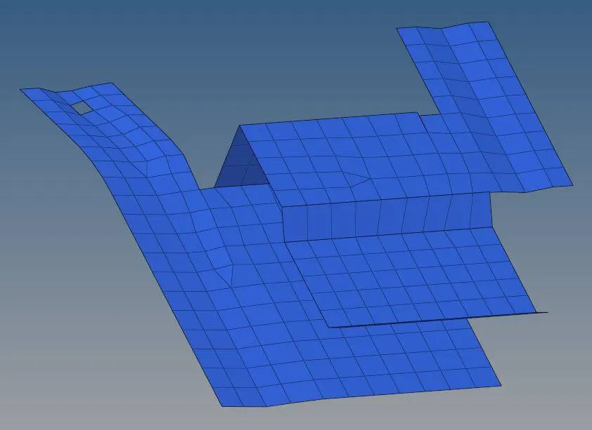
6) FINAL COMPONENT MESH: "After assigning Thickness in Properties"
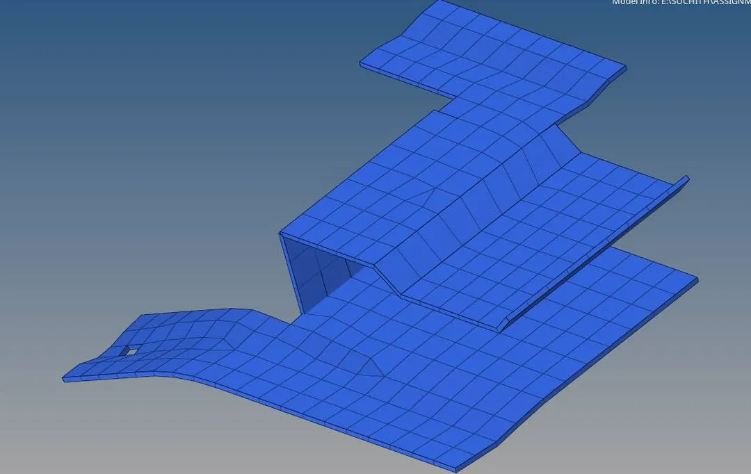
CONCLUSION:
Hence for all the given components, we have done:
- Geometry Clean up.
- Extracted Midsurface Geometry.
- Cleaned Midsurface Geometry.
- Created 2D Mesh With Target Length:5mm, Min element size:3.5mm and Max element size:7mm.
- And we have Assigned Proper Thickness to all the above given components.