Assignment 1
Objective:
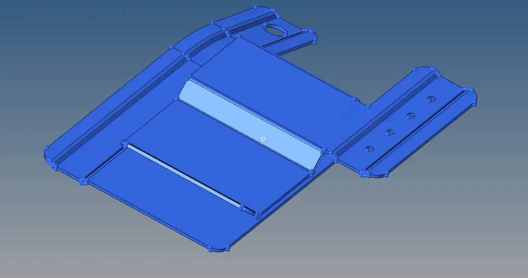
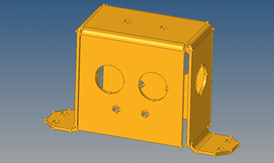
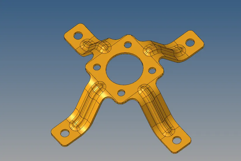
Carry out the geometry cleanup operation on the given 3 files which are as:
- Practice
- Clip Repair
- Mounting Bracket
There should not be any free edges, convert all of them into refine geometry.
- Clean the geometry.
- Extract midsurface.
- Clean midsurface geometry.
- Ignore holes less than dia 5mm.
- Create 2D mesh with target length 5mm, min 3.5mm max 7mm.
- And assign proper thickness, by creating a generic property.
- Then Save in .hm format.
Procedure:
1. Import the model to hypermesh.
2. Delete the solid in the model (Delete - Solid - Select Solids - Click delete entity)
3. Defeature the model using defeature tab and also remove surface fillets using surface edit option.
4. Clean the Geometry for free edges using the edit tools (i.e. filler surface, toggle edge)
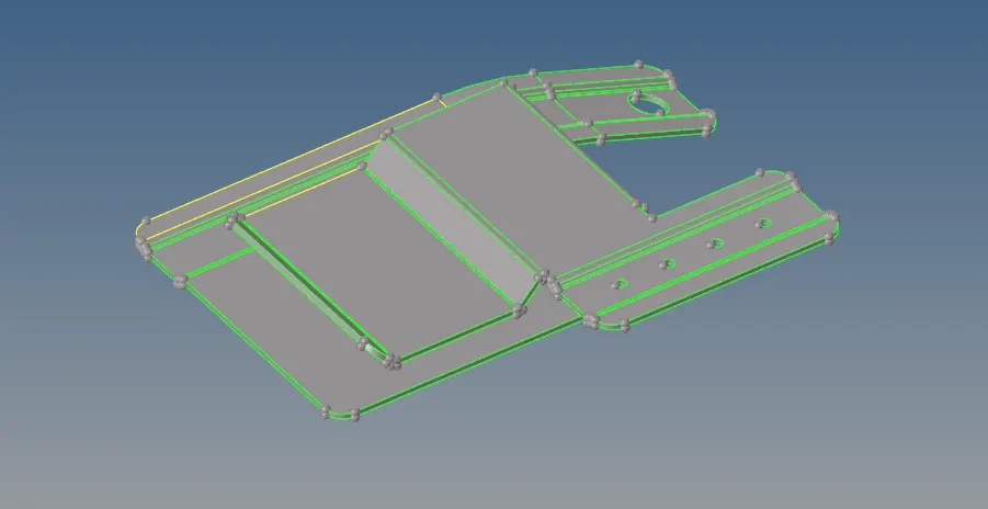
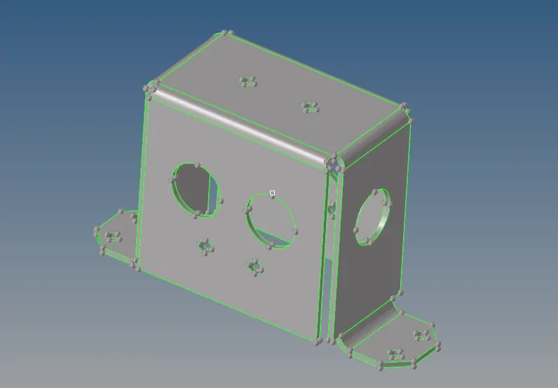
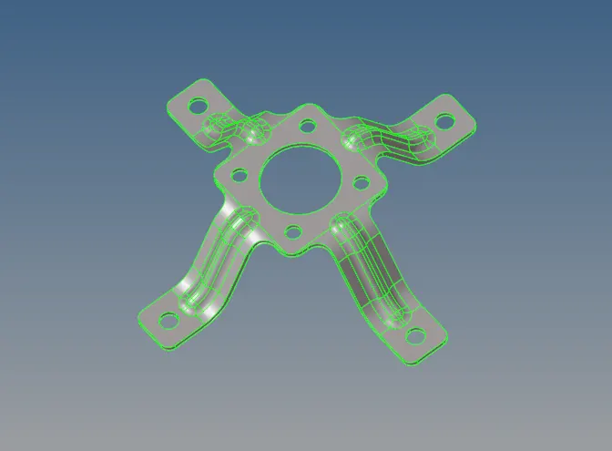
5.Create midsurface of component (Geometry - Midsurface - Extraction - Automidsurface - Select the surface - Click Extract).
Also, surface offset option is used in the complex model to create the manual midsurface by first calculating the distance between the inner and outer surface and further offsetting surface in between them. (Geometry - Surface edit - offset)
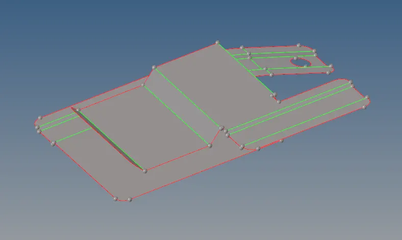
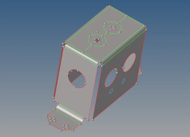
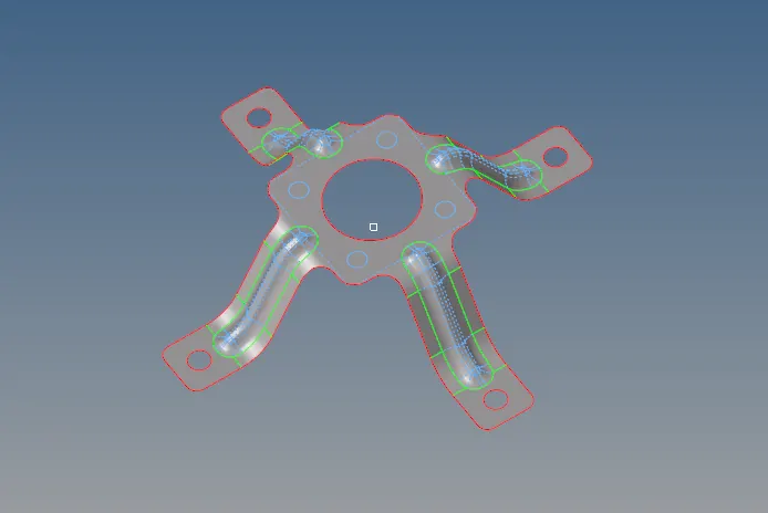
6. Cleanup the midsurface (Geometry - autocleanup - Select surface - create)
7. Make washer split for the internal holes and empty areas if its not created through Autocleanup (Geometry - quick edit - washer split - select offset value 5 - slect the line - Create). Fill the holes of less than 5 mm dia. and toggle the lines . Also remove the unecessary nodes and points using remove points drom dit tool
8. In case we have similar surface on both the ends the, it would be easy if the component is being trimmed into two halves and then work on one half of the component.
9. Mesh the 2-D component (2D - Automesh -Select the surface - Target size 5 - Create Mesh with type Mixed).
Note: Mesh all the surfaces one by one to get proper flow of mesh with minimum tria elements, Split the surfaces if required.
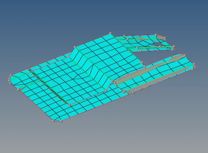
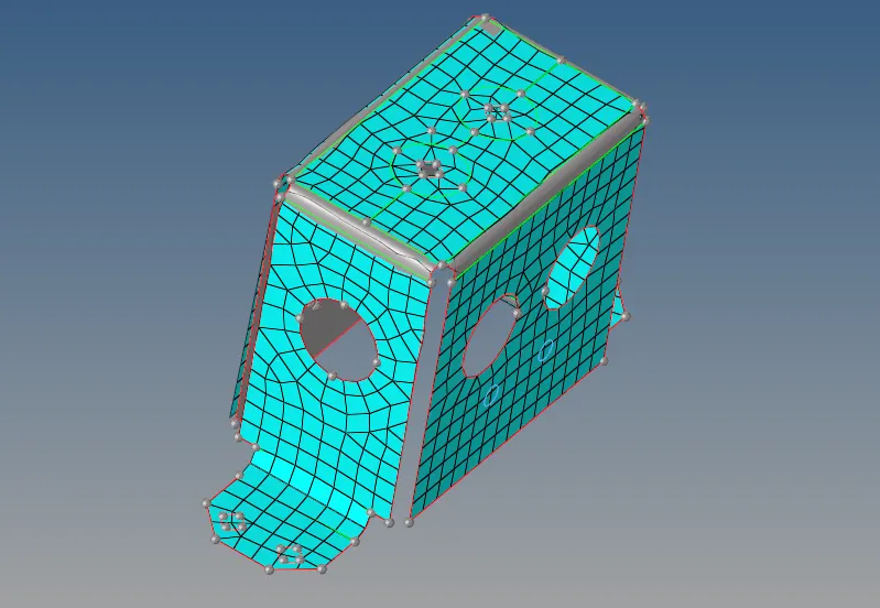
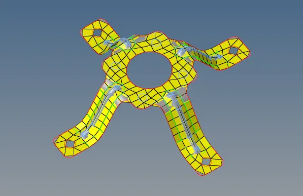
10. Edit the quality criteria values of minimum and maximum size as provided (Tool - Check element)
Also, Meshing criteria could be edited. (Preferences in toolbar - Meshing Criteria)
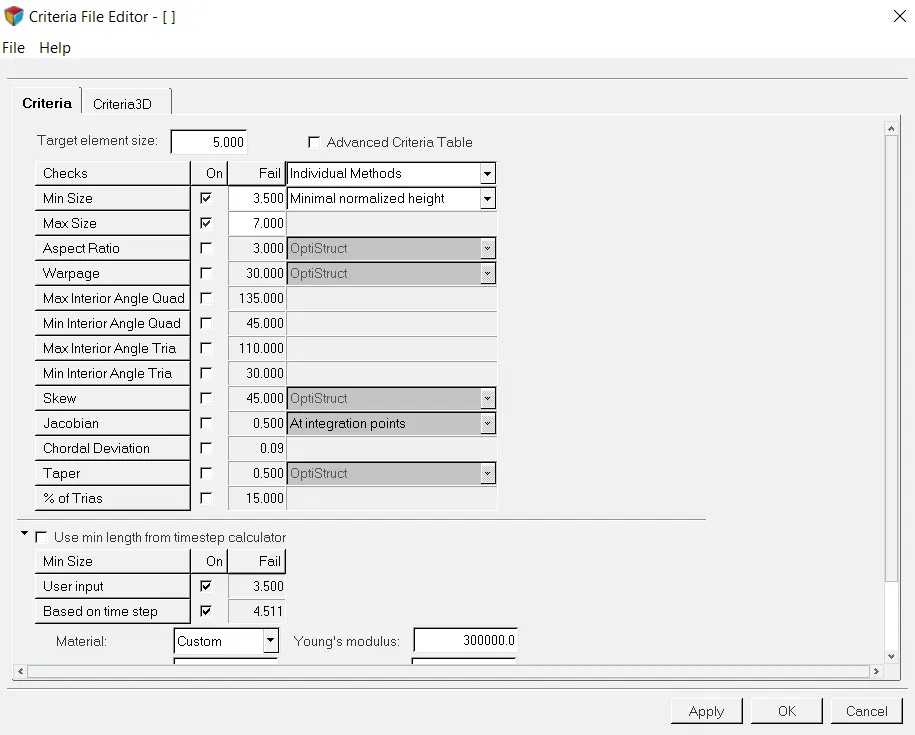
10. Tools used to meet quality criteria are as following to the failed elements as seen in the component in different color (red/yellow) :
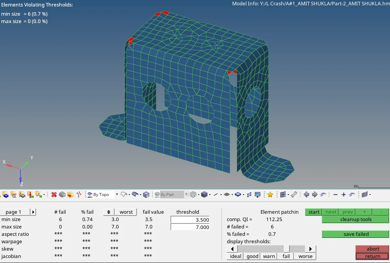
- Place node is used to move the nodes.
- Node/Element Optimize are used to optimize the respective Node/Element automatically.
- Smooth is used to smooth the curvatures.
- Drag tria element is used to drag out irrelevant trias.
- Split quad is used to split the quad into respective tria or quad.
- Combine tria is use to combine tria elemts to make a quad.
11. Some other Tools to meet quality criteria are as:
- Mask is used to mask failure elements so that they could be meshed and edited without disturbing complete mesh.
- Edit elements is used to Create, Split and Combine elements.
- Replace is used to replace the nodes
12.Also, reflect the elements (if the surface was disected because of symmetry) by duplicating elements and then using reflect tab from Tools option.
Further check for the edges and remove the eqivalence after refelcting. (First preview the equivalence in the component and the click equivalence tab.)
Also equivalence could be done wirh the shortcut key of F3

Repeat the above steps for each component seperately till there are no failing components and also there are no components failing in tool option check element. Also, we can provide material and the property such as thickness to our mesh by creating new property and Material in the Model tab.
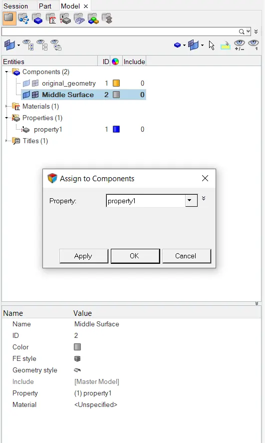
13. Save the model using save option which makes the model save in (.hm) file.
Result:
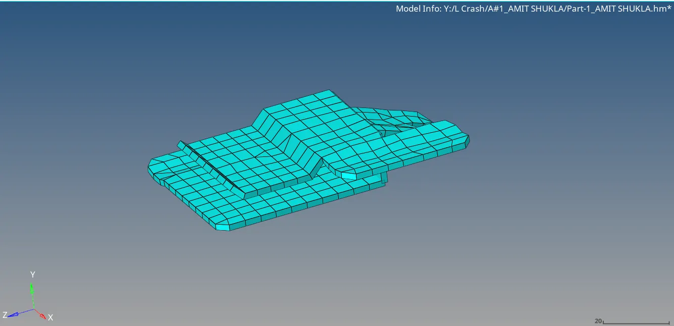
We have meshed and assigned thickness to the given models according to the specified instructions.
Component 1:
Component 2:
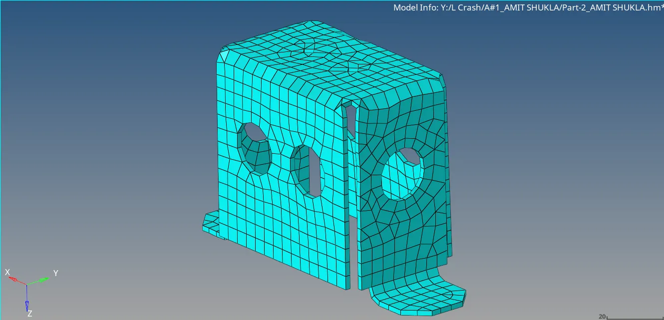
Component 3:
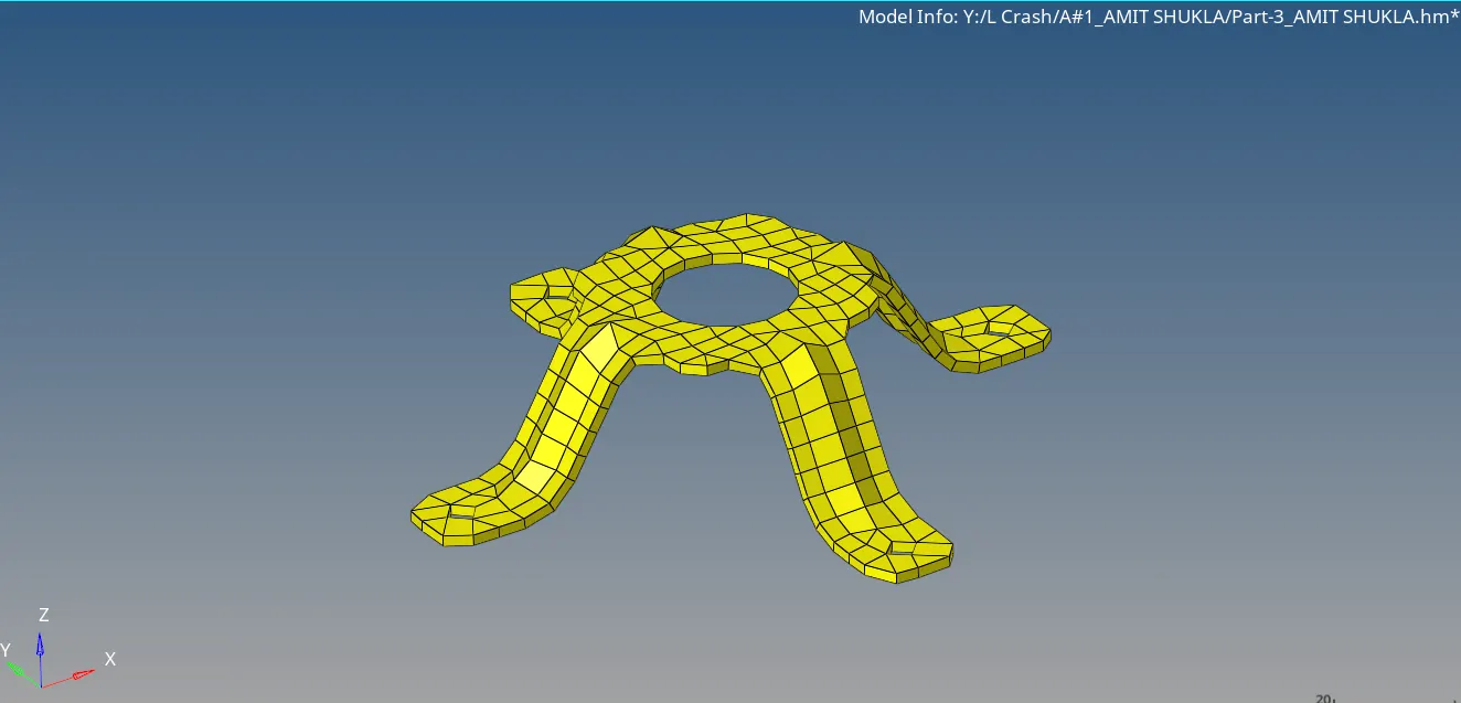
Conclusion:
We have learned to mesh and assign thickness given model using different tools.