Assignment 1
1. Explore the GUI of GT SUITE and list down modules available with brief description.
GT-SUITE is a product of Gamma Technologies (GTI), a specialist software company which is solely focused on the Engine and Vehicle Industry. GT-SUITE handles, in a single software tool, a wide variety of vehicle and engine technical applications. It contains all GT libraries and capabilities. The ideal choice for full vehicle design and analysis, GT-SUITE offers an all-inclusive package that provides an important cost advantage to users.
Modules under GT suite:
- Engine Performance and Acoustics.
- Exhaust Aftertreatment.
- Cooling Systems and Thermal Management.
- Air Conditioning/Waste heat recovery.
- Fuel injection.
- Hydraulics and Pneumatics.
- Lubrication Circuits.
- Vehicle and HEV Fuel economy & Performance.
- Transmission and shift quality.
- Crank train and Crankshaft dynamics.
- Valvetrain Kinematics and dynamics.
- Timing and Front-end drive systems.
- Engine Real-time.
- Aerospace Systems
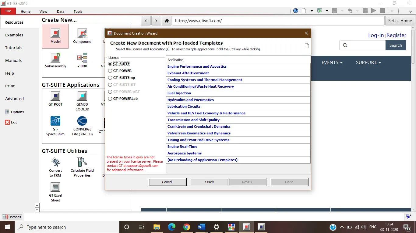
GT power: The industry-leading software for engine simulation with a detailed cylinder model and combustion analysis.
It has the following applications:
- Engine performance and Acoustic.
- Exhaust after-treatment.
- Evaporative emission.
GT suiteEmp: It serves as a multi-physics platform to construct models in a wide range of applications including Cooling Systems and Thermal Management, Vehicle and HEV Fuel Economy, Hydraulics and Pneumatics, and many more.
It has the following application:
- Cooling system and thermal management.
- Air conditioning.
- Fuel injection.
- Hydraulics and Pneumatics.
- Lubrication circuits.
- Crank train and crankshaft dynamics etc;
2. Locate following settings:
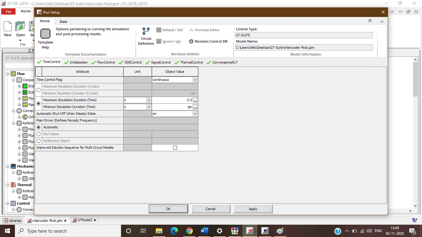
- Time control flag
In flow control tab> home tab> Run setup> Time control > in the table below the attribute Time control flag is given:
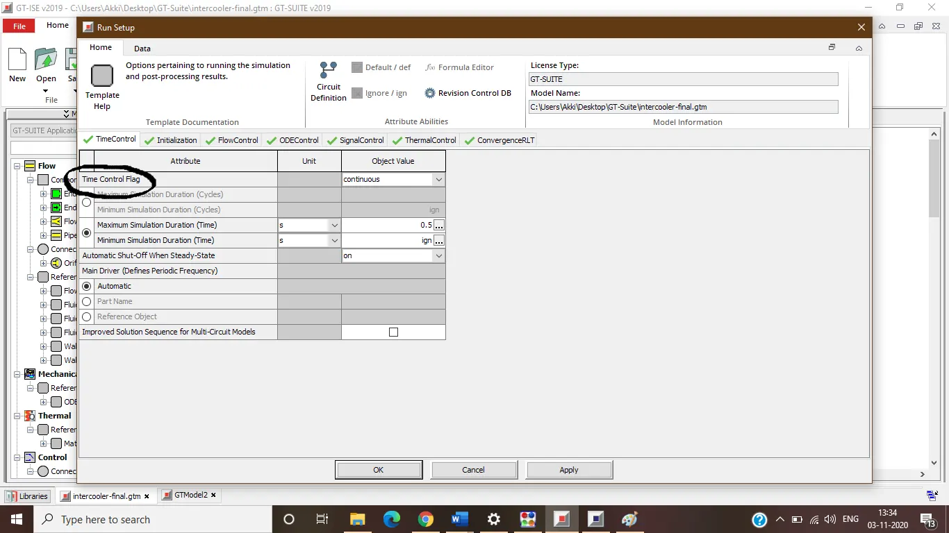
Defines the global simulation type with regard to time. One of the following options can be used: periodic indicates that the model contains at least one circuit which contains a periodic event (i.e. engine cylinder “cycle”) and therefore requires tracking of results with respect to angle over each cycle. Any model that includes an ' EngineCrankTrain', ' Crank Analysis’, or ' Engine Crankshaft' part should use the periodic option. Note that the simulation duration for a periodic simulation can be specified in cycles or in time, whichever is most convenient.
continuous indicates that the simulation includes no periodic event, and therefore has no need to track results with respect to a cyclic angle. This is the typical setting for models that contain only quasi-steady fluid circuits such as coolant air. The simulation duration for a continuous simulation is typically specified in time
- Time step and solution control
this is also found under run setup and under flow control inside attributes column, second cell is Time Step and Solution Control Object.
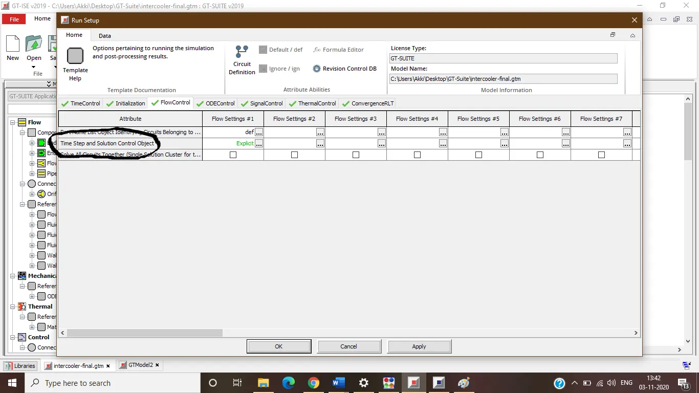
It gives us different explicit options to set for flow.
- Integrator/Solver type
this is also found under Run Setup and under ODE Control inside attributes column, fourth cell is Time Step and Solution Control Object;
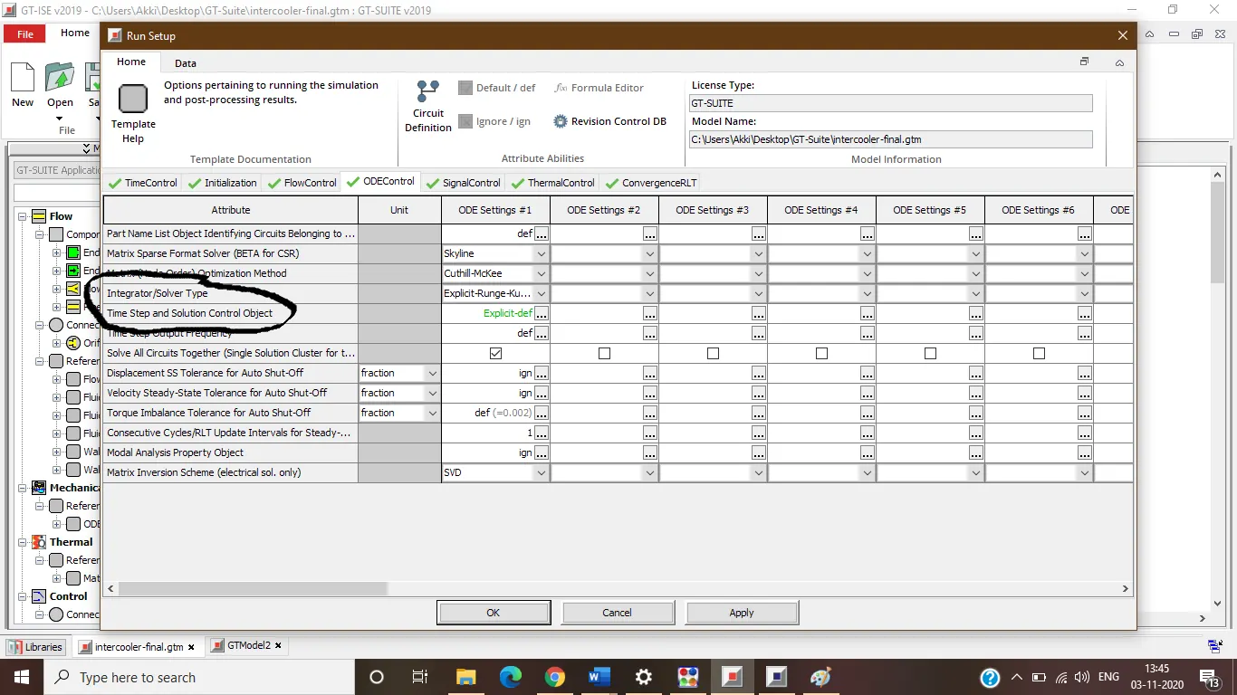
3. Explore intercooler tutorial and note down all settings of
- Run setup
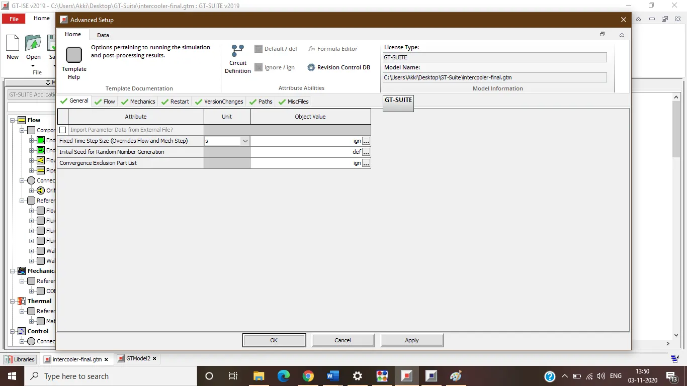
- Advanced setup
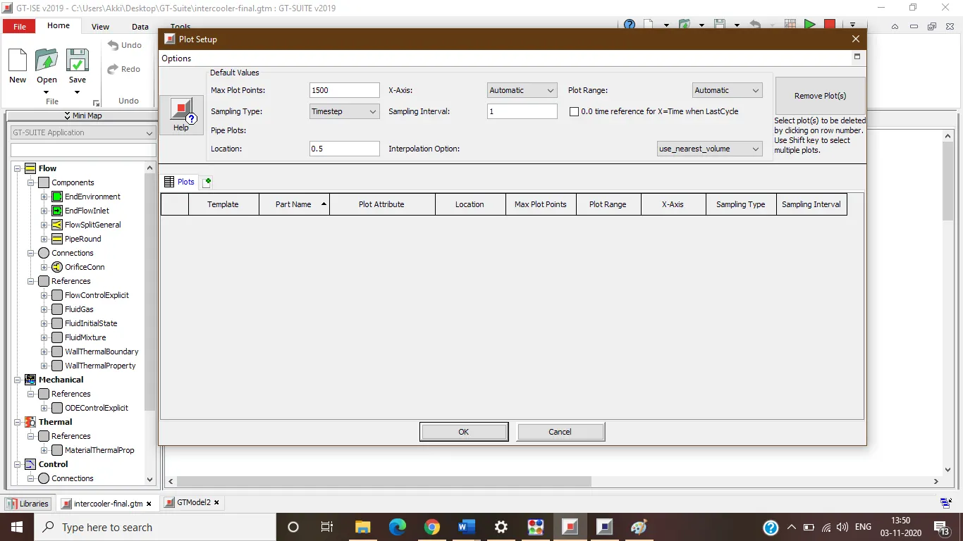
- Plot setup
- Output setup
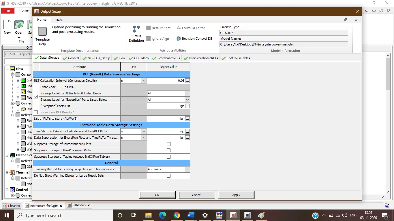
File>Tutorials>Modelling Apllications>Engine Performance>06-6cylDlturbo>intercooler-final.gtm. Also, you can use the search bar under tutorials section to get the required file directly:
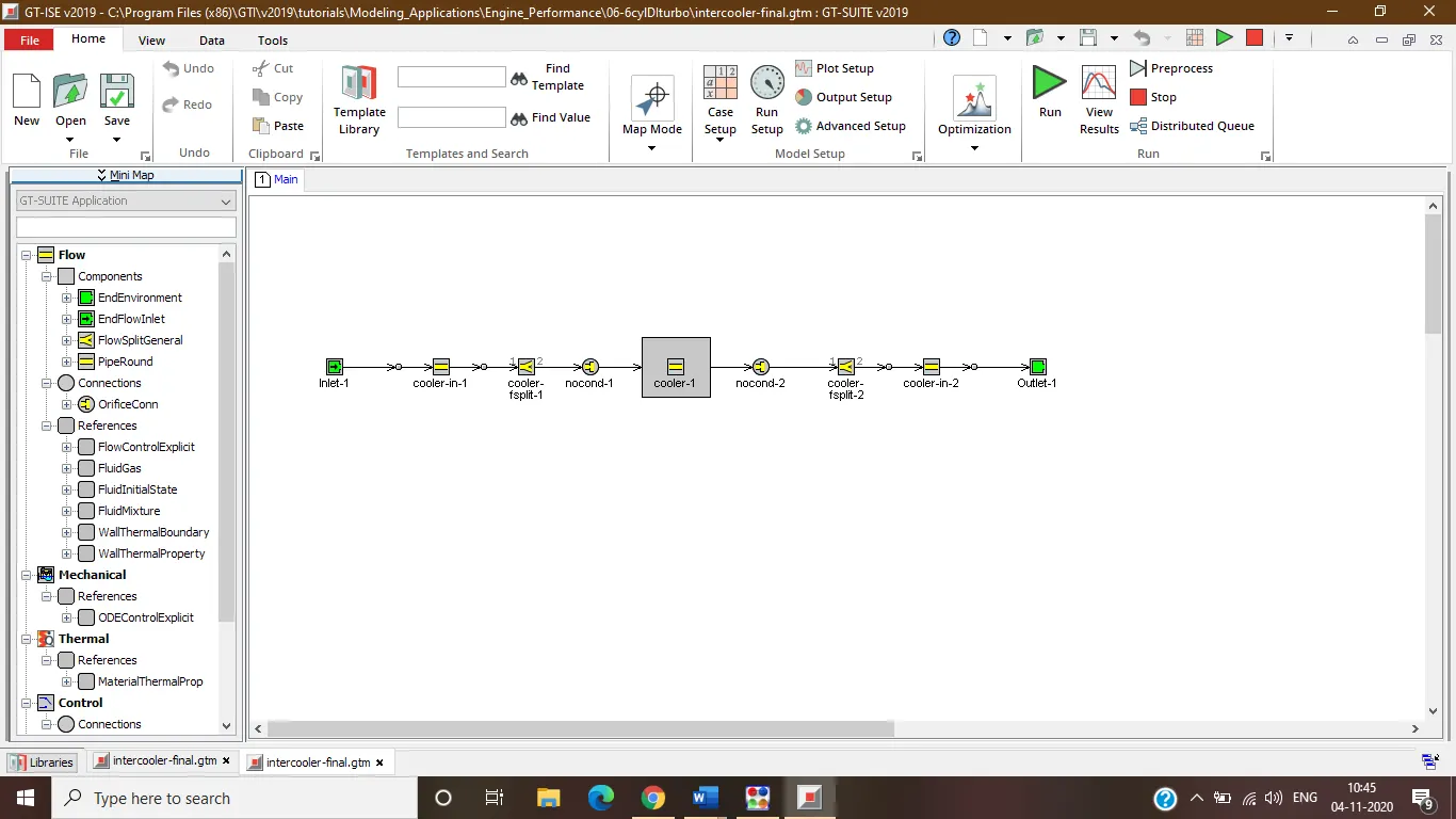
4. Problem
Given:
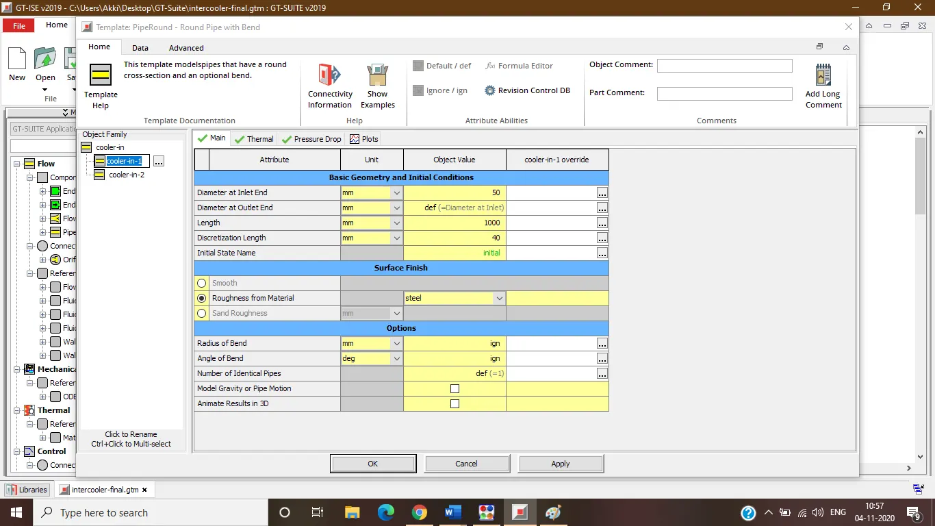
Diameter of cooler inlet and outlet pipe= 50 mm
Length of the CAC= 1000 mm
Inlet mass flow rate = 1200 kg/h at 100 degC
Outlet pressure 2 bar at 30 degC
Exploring GT SUITE and Intercooler Simulation:
Solution
Using the Inter-cooler Tutorial (File>Tutorials>Modelling Apllications>Engine Performance>06-6cylDlturbo>intercooler-nal.gtm) the problem is solved.
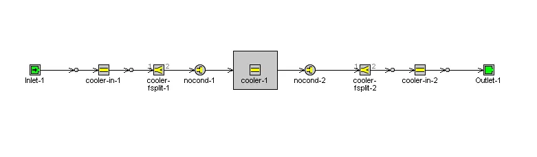
Diameter of cooler inlet and outlet pipe= 50 mm and Length of the CAC= 1000 mm is set by double clicking the cooler-1 from above flow plan which is shown below:
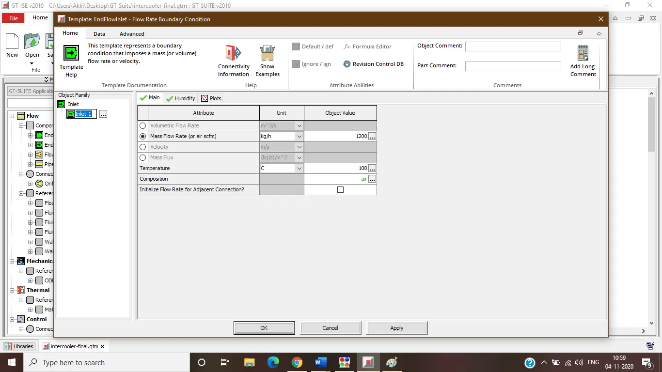
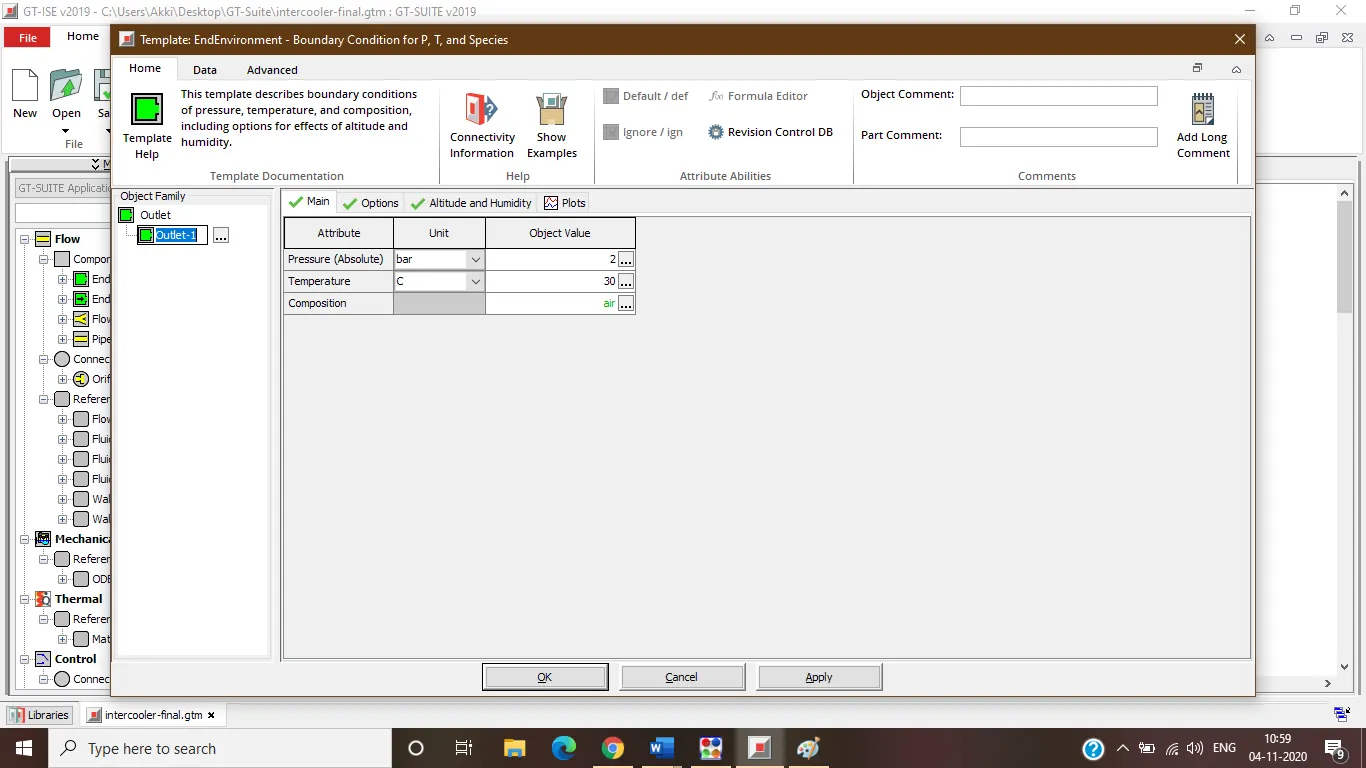
By clicking on Inlet-1, Inlet mass ow rate = 1200 kg/h at 100 degC and Outlet pressure 2 bar at 30 degC is set:
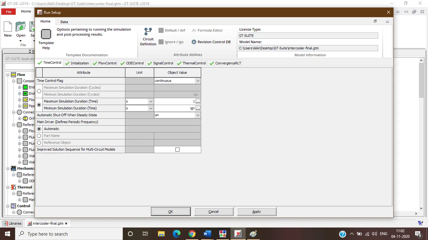
In the run setup change maximum simulation duration to 1 sec
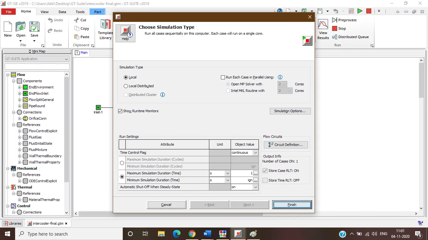
And give a run to simulation.
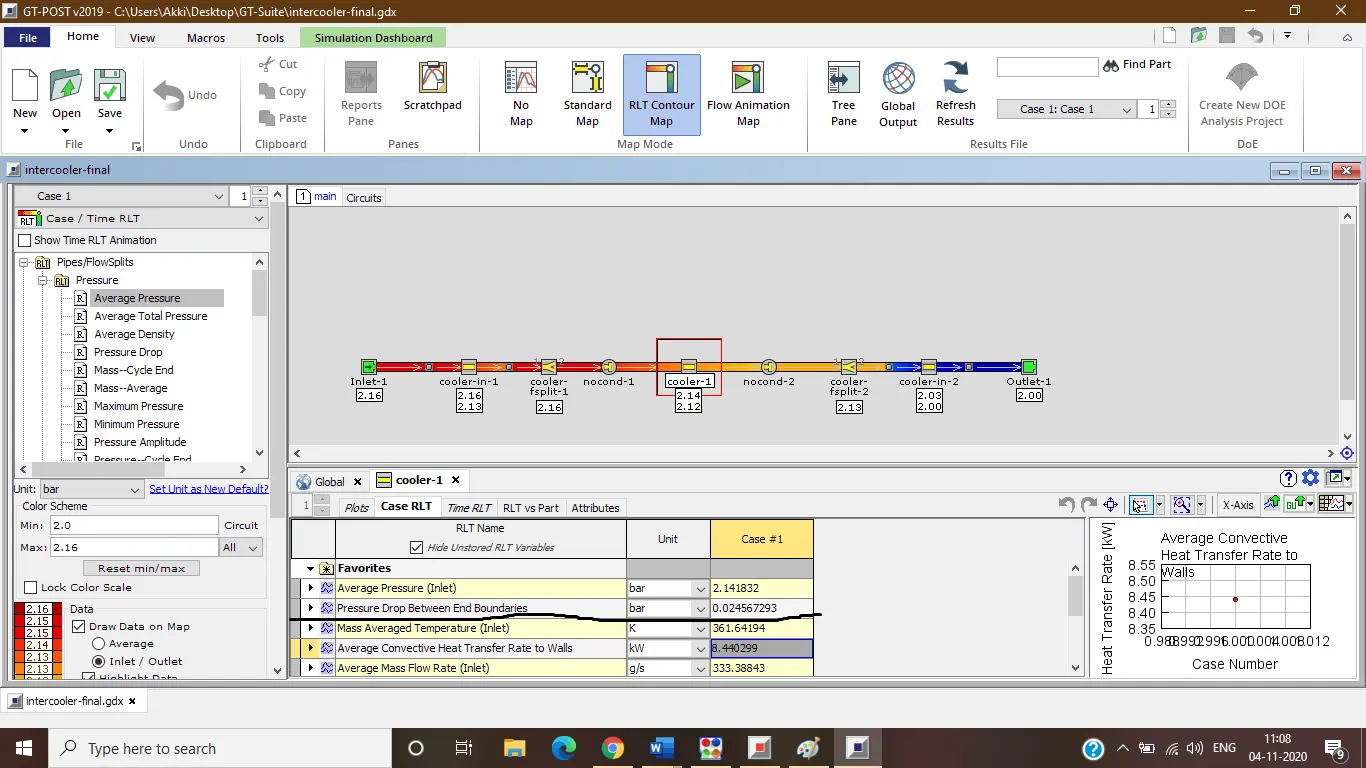
The total heat transfer at Charge air cooler (CAC) = 8.440299 KW
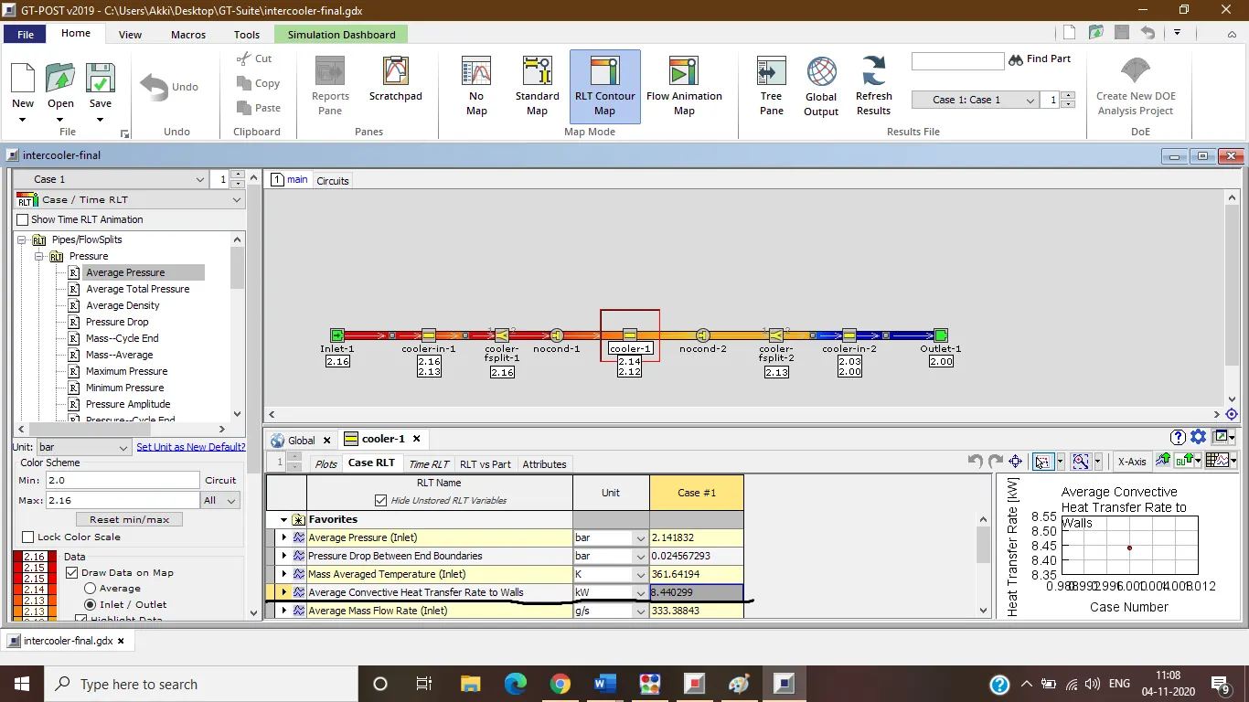
Calculate pressure drop across CAC = 0.024567296 bar