2D Meshing with Geometry clean up and Extracting Midsurface operation using Hypermesh
AIM :
To carry out the geometry cleanup operation on the given 3 files.
- Practice
- Clip Repair
- Mounting Bracket
There should not be any free edges, convert all of them into rerfine geometry.
- To Clean the geometry
- To Extract midsurface and to Clean Midsurface geometry and ignore holes less than dia 5mm.
- To create 2D mesh with target length 5mm, min 3.5mm, max 7mm.
- To assign proper thickness, by creating a generic property.
PROCEDURE :
Importing CAD Model and Geometry Cleanup :
1. Import the given model in Hypermesh by using File --> Open --> Model.
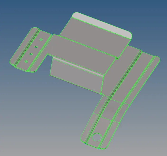
Fig : Part-1
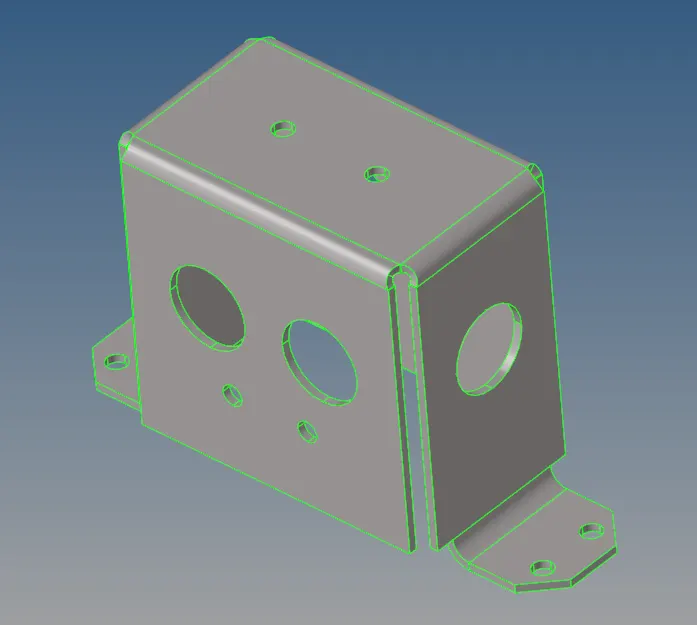
Fig : Part-2
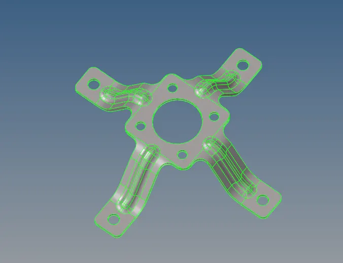
Fig : Part-3
2. After Importing the given Model and Clean up the Geometrical errors by checking visually.
3. For Cleaing the above geometrical error, Go to Geom-->quick edit
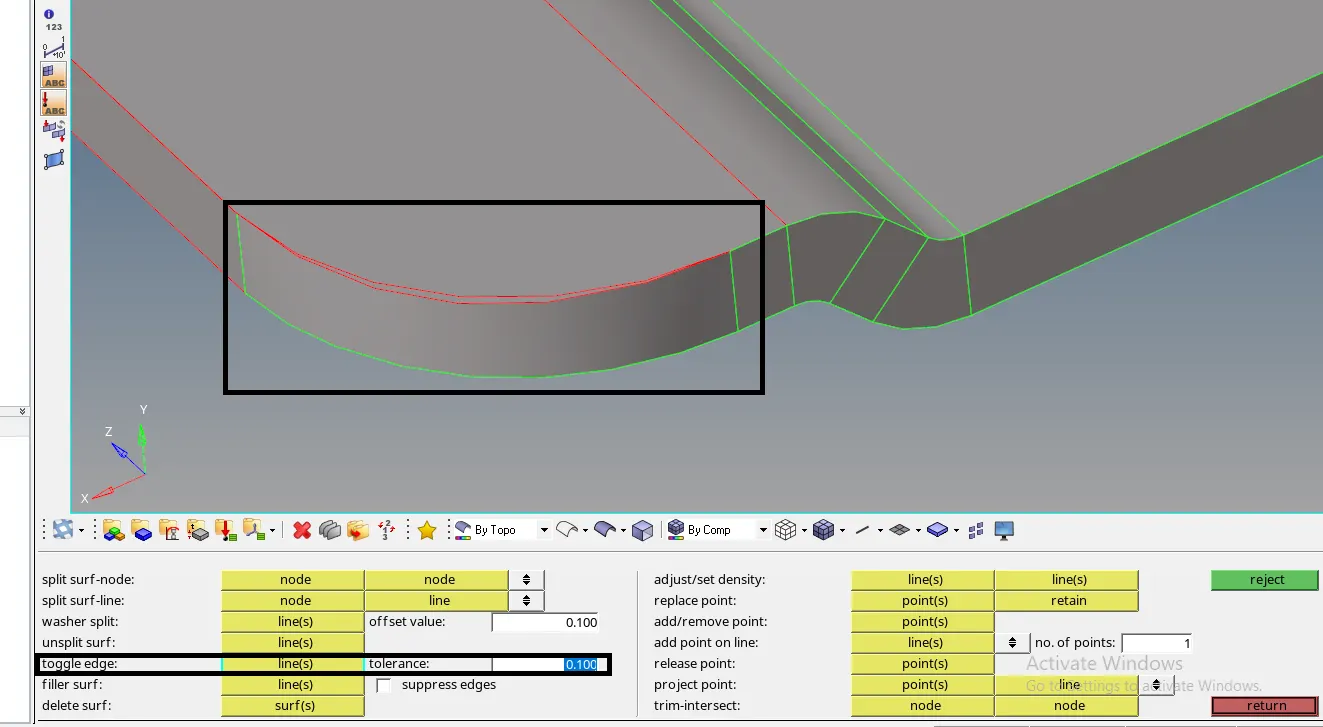
Fig : Geometrical Error -1
4. Use toggle edge option and Click on the red line. If the error is not cleared, increase the tolerance and clear the error.
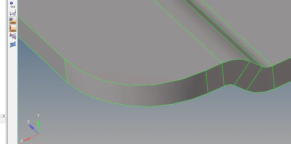
Fig : Cleanup -1
5. After Clearing the above error, check the model to find other geometrical errors.
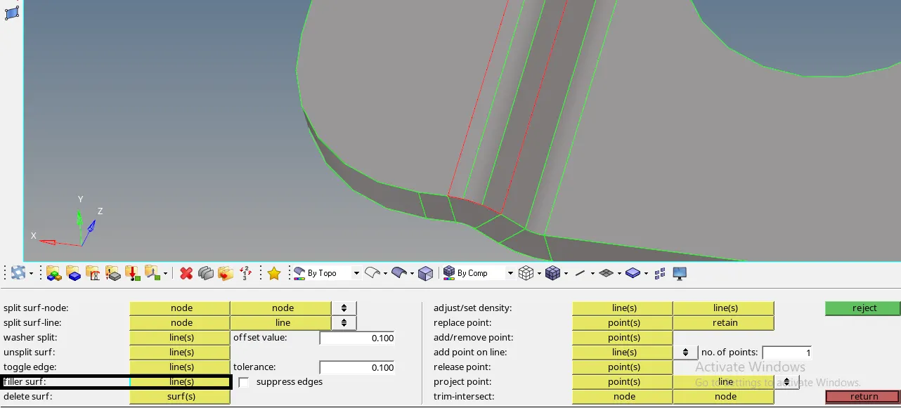
Fig : Geometrical error - 2
6. Use filler surf option to clear the above geometrical error.
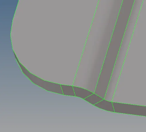
Fig : Cleanup-2
7. Trim the excess geometry in the given model and Go to Geom-->surface edit
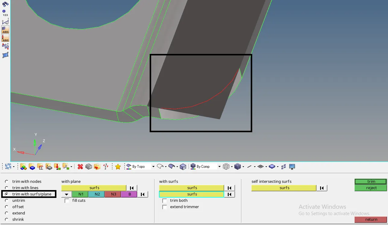
Fig : Geometrical error - 3
8. Use trim with surfs/plane option and select the two surfaces and trim it.
9. After using trim option, Delete the excess surface using Delete-->Surfs option.
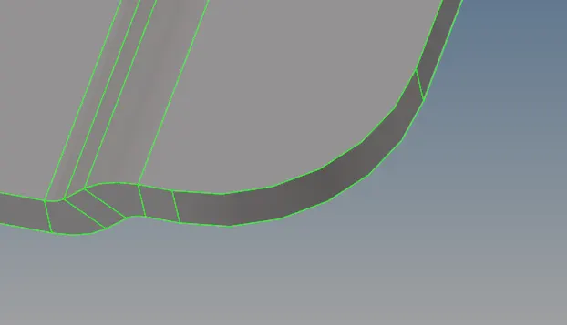
Fig : Cleanup - 3
10. After Clearing the Geometrical error, extract the midsurface.
Extracting Midsurface :
1. For extrcating Midsurface for the given model, Go to Geom-->midsurface.
2. Use autoextraction option and select the all Surfaces and extract the midsurface.
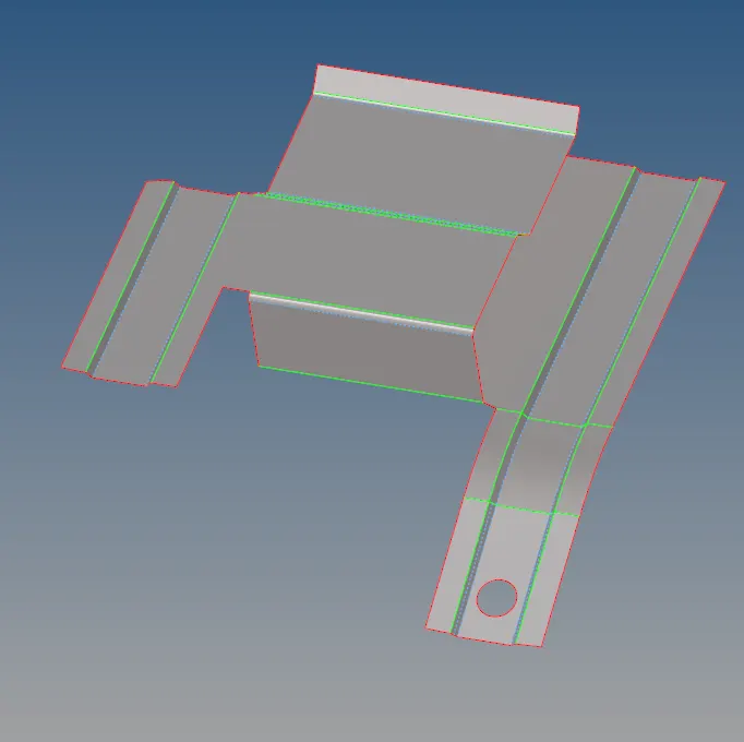
Fig : Part-1 Midsurface
3. If the auto midsurface option is not extracting the proper midsurface, Use offset method.
4. Go to Geom-->surface edit-->offset option and select the surface to offset.
5. After selecting the surfaces and give offset value and make duplicate the original component and click offset.

Fig : offset method to extract midsurface
6. After giving offset, Midsurface will be created for the CAD geometry.
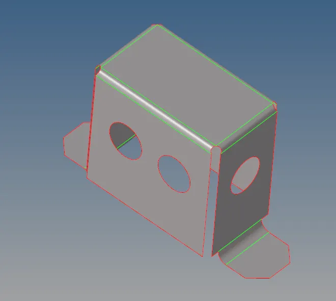
Fig : Part-2 Midsurface
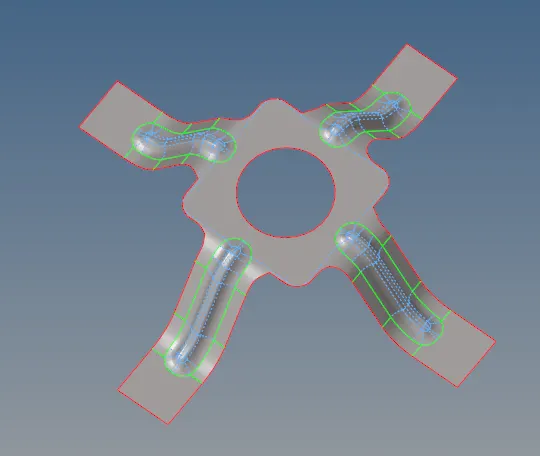
Fig : Part-3 Midsurface
MESHING :
1. After creating a Midsurface of the component, Assign the given Quality criteria of the component.
2. Go to 2D-->elem cleanup option and select edit criteria to assign the given Quality criteria.
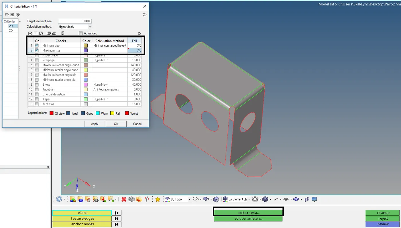
Fig : Assigning Quality criteria
3. After assigning Quality criteria, start Meshing for the Midsurface component.
4. Go to 2D-->automesh option and select surface to mesh and set target length in element size column and click mesh.
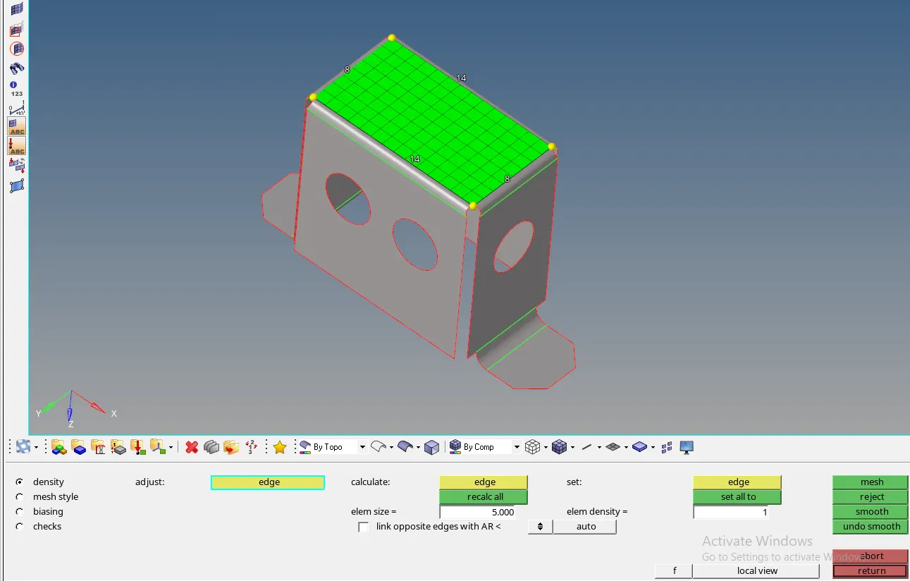
Fig : Meshing Operation
5. If the two surfaces are similar, mesh one side of the surtface and reflect to other side of the surface by using tools-->reflect or tools-->position option.
6. After meshing the Component, check the quality and clear the errors.
7. Go to 2D-->qualityindex and Cleanup the quality error using cleanup tools.
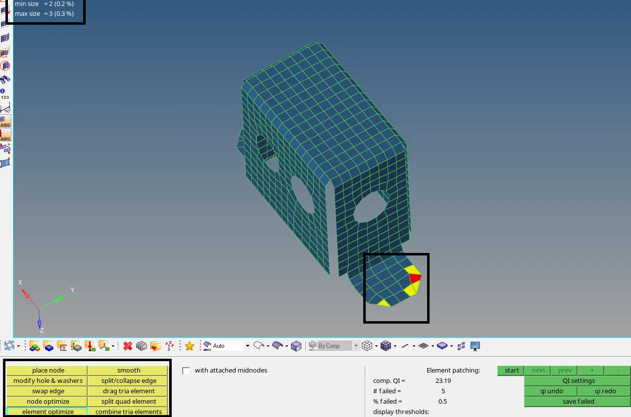
Fig : Element Cleanup
8. After clearing quality errors and also clear trias, quads in the meshing.
9. Final assign the thickness for the meshing component.
10. Go to Tools-->Organize option to move the mesh part to the original geometry.
11. After moving mesh part to the original geometry, assign thickness in the property id.
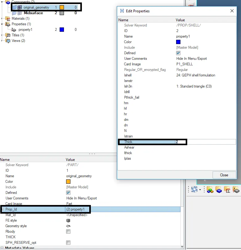
Fig : Assigning thickness by creating a generic property
12. After assigning Thickness, Select 2D Detailed Element Representation Option to display thickness assigned to the component.
RESULT :
2D Meshing has been created with target length 5mm, min 3.5mm, max 7mm and assigned proper thickness, by creating a generic property for the given CAD models.
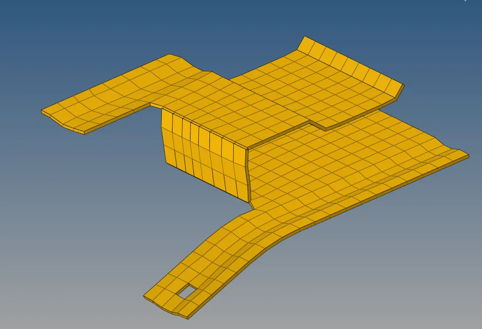
Fig : Practice Model
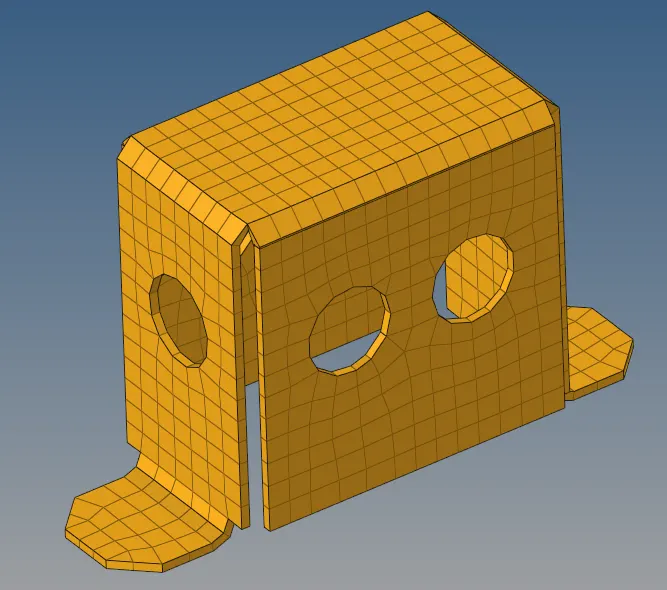
Fig : Clip Repair Model
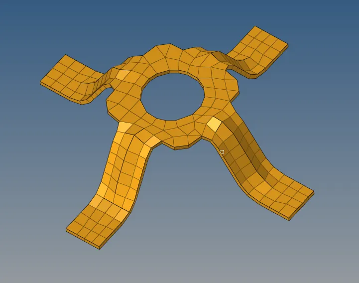
Fig : Mounting Bracket Model