Assembly of Yacht
Radar_Mast_Amir: -
https://drive.google.com/file/d/1LlZzAg3GasLZ1HO1pR3jwa2V9O8zmhZB/view?usp=sharing
radar mast images: -
https://drive.google.com/drive/folders/1QHIHlD_XvBQgetUMnh9VyuyLGGhtaf1q?usp=sharing
Yacht_Assembly_Amir: -
https://drive.google.com/file/d/16PQR2x2_-a2597NZlYfh0_wS0sxutVGl/view?usp=sharing
Yacht images: -
https://drive.google.com/drive/folders/1xiFCwyTz7A0zcWPGLo1E4q3Fz2LEXaa3?usp=sharing
YACHT ASSEMBLY
Objective: - The main objective of this project is to design and model Yacht by using different tools and commands in solidworks, to assemble different parts of Yacht and to create photo realistic view of the Yacht by rendering the model in photo view 360.
Part Modelling: - In part modelling different parts of an item are sketched and then these are modelled using various graphical visualisation.
Features Description:-
Sketch: - sketch is used to represent the two dimensional state of the model. Solidworks includes different types of sketches such as line, circle, spline etcetera.
Offset: - Offset one or more sketch entities, selected model edges, or model faces by a specified distance.
Extrude Boss/base: - An Extruded Boss/Base feature will allow you to take a 2D sketch and add thickness to it in the third dimension.
Fillet: - Fillet/Round creates a rounded internal or external face on the part.
Loft: - Loft creates a feature by making transitions between profiles. A loft can be a base, boss, cut, or surface. You create a loft using two or more profiles. For a solid loft, the first and last profiles must be model faces or faces created by split lines, planar profiles, or surfaces.
Dome: - select one or more planar or non planar faces. You can apply domes to faces whose centroid lies outside the face. This allows you to apply domes to irregularly shaped contours.
Extrude cut: - The Extruded cut operation allows you to easily remove material from a solid by extruding a profile along the normal to its plane.
Split: - The SOLIDWORKS Split Line tool is used to project an entity (sketch, solid, surface, face, plane, or surface spline) onto other surfaces or curved/planar faces. You are also able to split faces on multiple bodies with one command.
Trim entities: - Select the trim type based on the entities you want to trim or extend. All trim types are available with 2D sketches and 2D sketches on 3D planes. You can use any of the following trim options: Power trim.
Revolve: - Revolves add or remove material by revolving one or more profiles around a centreline. Create revolved boss/bases, revolved cuts, or revolved surfaces. The revolve feature can be a solid, a thin feature, or a surface.
Dynamic mirror: - Dynamic Mirror Entity works by automating the mirror entities tool while you are sketching. When this tool is activated, SOLIDWORKS will automatically create a symmetric relation between the original sketch, the copied sketch, and the line that the sketch is being mirrored over.
Appearances: - An appearance defines the visual properties of the model. It does not affect physical properties, which are defined by material.
Combine: - Combine feature uses multi bodies to create a single body.
Shell: - The shell tool hollows out a part, leaves open the faces you select, and creates thin-walled features on the remaining faces.
Chamfer: - The chamfer tool creates a bevelled feature on selected edges, faces, or a vertex.
Circular pattern: - circular patterns create multiple instances of one or more features that you can space uniformly around an axis.
Linear pattern: - linear pattern creates multiple instances of one or more features that you can space linearly.
Surface modelling: - surface modelling gives you the ability to built out a visual representation of an object’s exterior and its contours.
Features description:-
Lofted surface: - loft surfaces are 3D surfaces generated by multiple 3d curves or existing edges creating a smooth tangency between the selected curves.
Swept surfaces: - sweep surfaces are surfaces that are generated from a section curve positioned along a path.
Filled surfaces: - the filled surface feature constructs a surface patch with any number of sides within a boundary defined by existing model edges including composite curves.
Surface trim: - surface trim tool is used to trim intersecting surfaces.
Extend surface: - extend surface is used to extend a surface by selecting an edge, multiple edges, or a face. For edges, the surface extends along the plane of the edge.
Surface knit: - Knit Surface is used to combine two or more faces and surfaces into one. Knit surfaces absorb the surface bodies you used to create them.
Parts modelled for Yatch:-
Propeller
Radar
Hull
Garage Door
Front Seat
Middle Seat
Rear Seat
Superstructure
Radar Mast
Description of parts used: -
- Propeller: - A propelleris a rotating fan-like structure which is used to propel the ship by using the power generated and transmitted by the main engine of the ship.
Features used: -
Revolve
Loft
Extrude Cut
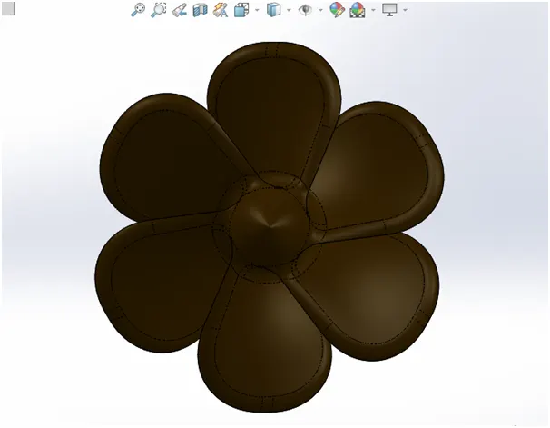
- Radar: - radars on ships, usedto detect other ships and land obstacles, to provide bearing and distance for collision avoidance and navigation at sea. Radar is a vital navigation component for safety at sea and near the shore.
Features used: -
Extrude
Extrude cut
Split Line
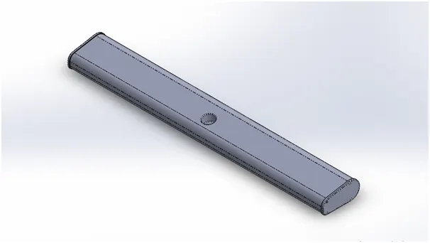
- Hull: - The hullof a ship is the most notable structural entity of the ship. To define the hull, it can be said that it is the watertight enclosure of the ship, which protects the cargo, machinery, and accommodation spaces of the ship from the weather, flooding, and structural damage.
Features used: -
Surface loft
Projected curve
Surface trim
Extrude
Knit
Surface Fill
Shell
Extrude cut
Sweep
Revolve
Dome
Spiral Curves
Plane
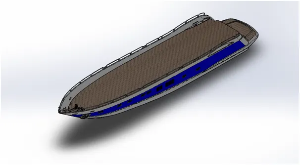
- Garage Door: - Garage doors in a shipare frequently large enough to accommodate automobiles and other stuff. Small garage doors may be made in a single panel that tilts up and back across the garage
Features Used: -
Extrude cut
Shell
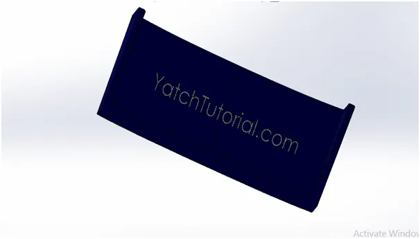
- Front Seat: - Seatsand chairs can be used on the fast ferry, high-speed passenger ship, cruise ship, catamaran, crew boat,, cargo ship, the sightseeing ships for sitting purposes.
Features Used: -
Sweep
Surface Extrude
Surface Trim
Surface fill
Loft
Knit
Revolve
Extrude cut
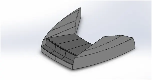
- Middle Seat: - Seatsand chairs can be used on the fast ferry, high-speed passenger ship, cruise ship, catamaran, crew boat,, cargo ship, the sightseeing ships for sitting purposes.
Features Used: -
Extrude
Chamfer
Cut Extrude
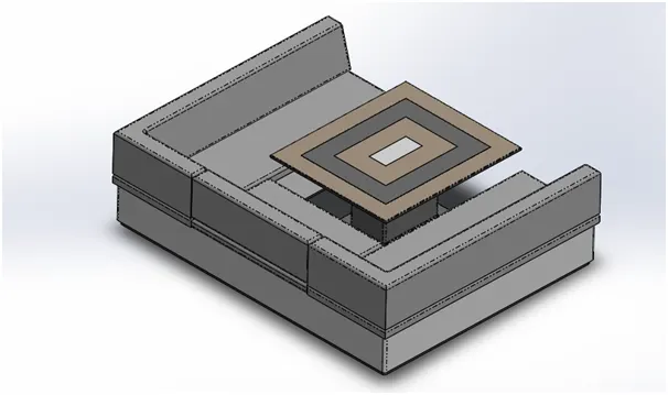
- Rear Seat: - Seatsand chairs can be used on the fast ferry, high-speed passenger ship, cruise ship, catamaran, crew boat,, cargo ship, the sightseeing ships for sitting purposes.
Features Used: -
Surface sweep
Surface offset
Surface trim
Ruled surface
Surface knit
Extend Surface
Surface Extrude
Loft
Extrude
Extrude Cut
Chamfer
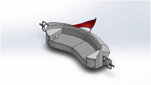
- Superstructure: - A superstructureis an extended construction of any building or platform that rises above the rest of the building or platform in a distinct manner. ... Thus, superstructure means to add a construction to an already existing structure. In ships this is the name given to the part of the ship that emerges from the deck.
Features Used: -
Surface Extrude
Sweep
Knit
Ruled Surface
Surface trim
Surface Loft
Surface Fill
Extrude
Cut Extrude
Dome
Plane
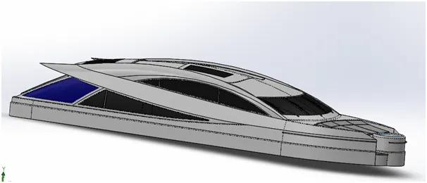
- Radar Mast: - Radar Mast is pole on which radar stand is created and radar is mounted upon it.
Features Used: -
Extrude
Revolve
Plane
Sweep
Chamfer
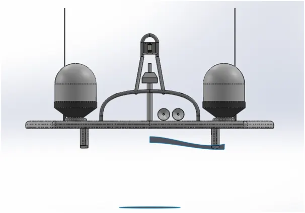
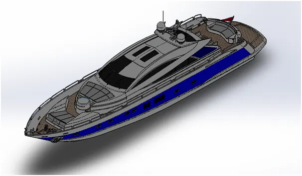
Assembly of Yacht: - - at first the Hull part is inserted in the assembly by using insert parts in the option. After that the part is inserted in the assembly environment and clicked ok to fix the Hull. After that the other parts of the Yacht are inserted into the assembly and given possible mate conditions.
Features used to assemble American chopper:-
Mates
Insert part
Mates: - mates create geometric relationships between assembly components. As we add mates, we define the allowable directions of linear or rotational motion of the components. We can move a component within its degree of freedom, visualising the assembly behaviour.
Insert parts: - we can insert the other components which need to be mated with the prime fixed component.
RENDERING :-
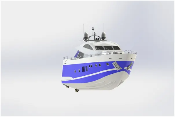
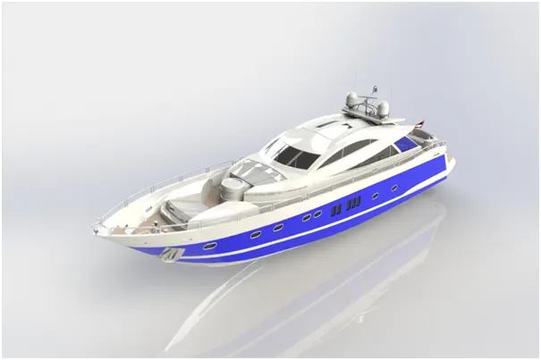
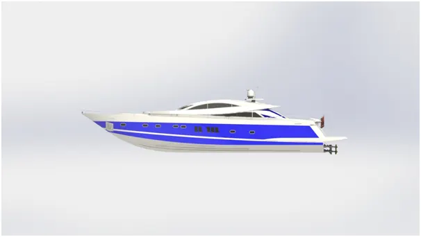
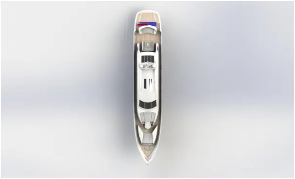
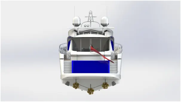
Rendering is the process of creating realistic images of photorealistic model with the environment.
Rendering is done in photo view 360 in solidworks.
In photo realistic model some of the mate conditions and positions are changed to render realistic model.
Then the photo realistic model is rendered into realistic images with different views.
Here i have assembled American chopper using photo view 360 for rendering.
CONCLUSION:-
- The parts of Yacht are modelled.
- The parts inserted into the assembly environment and Yacht is assembled.
- The photo realistic image was rendered using photo view 360.
I would like to thanks my mentor Mr. Soundar Rajan for helping me with the challenges I faced while modelling this Yacht.