Assembly of Yacht
google drive link: https://drive.google.com/drive/folders/1SrhRbTvL_IT5ZafJ3pB7QOAi2QuPEqu_?usp=sharing
SURFACE AND SOLID MODELLING OF SUNSEEKER PREDATOR YACHT WITH ASSEMBLY
ABSTRACT
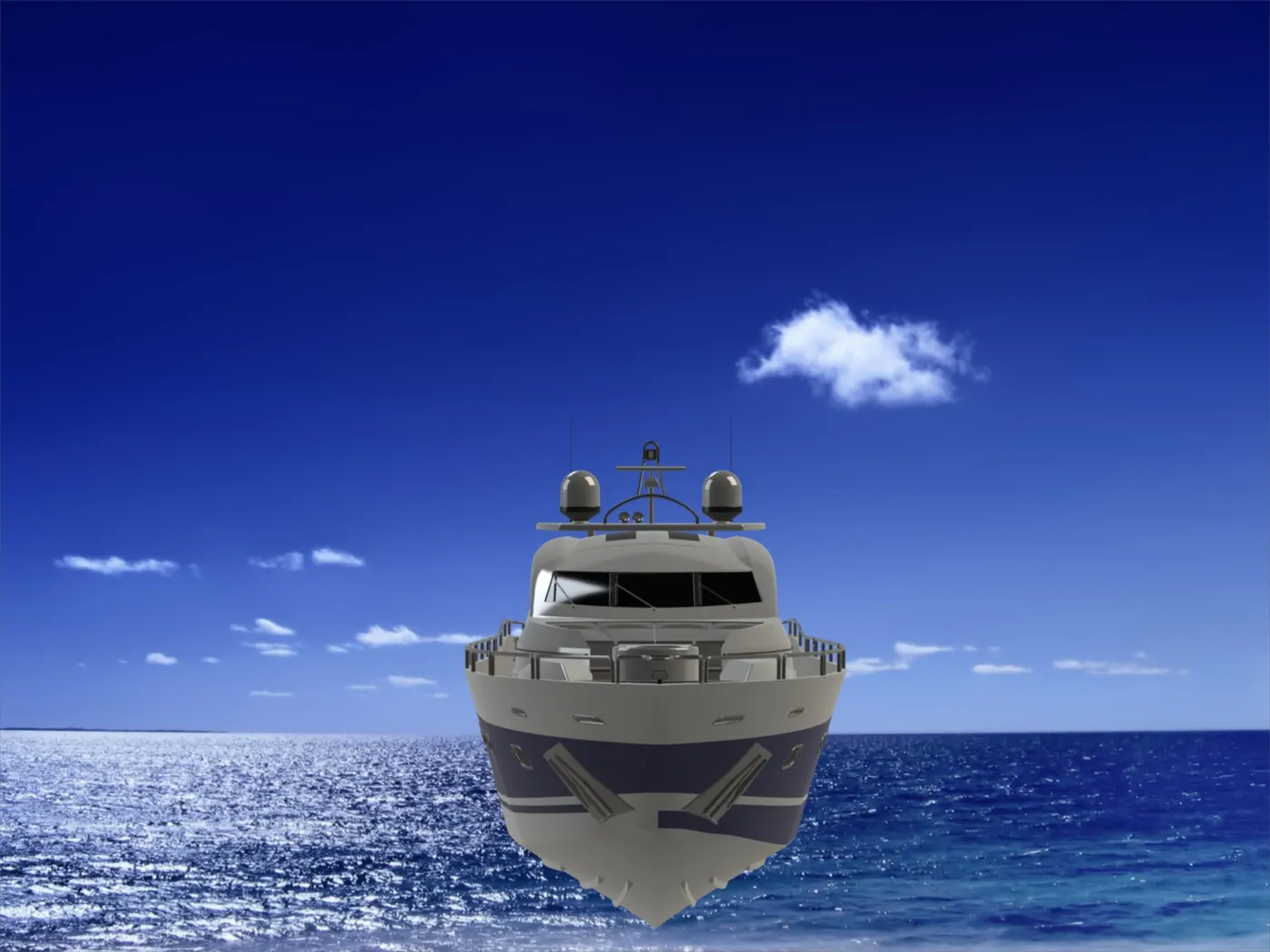
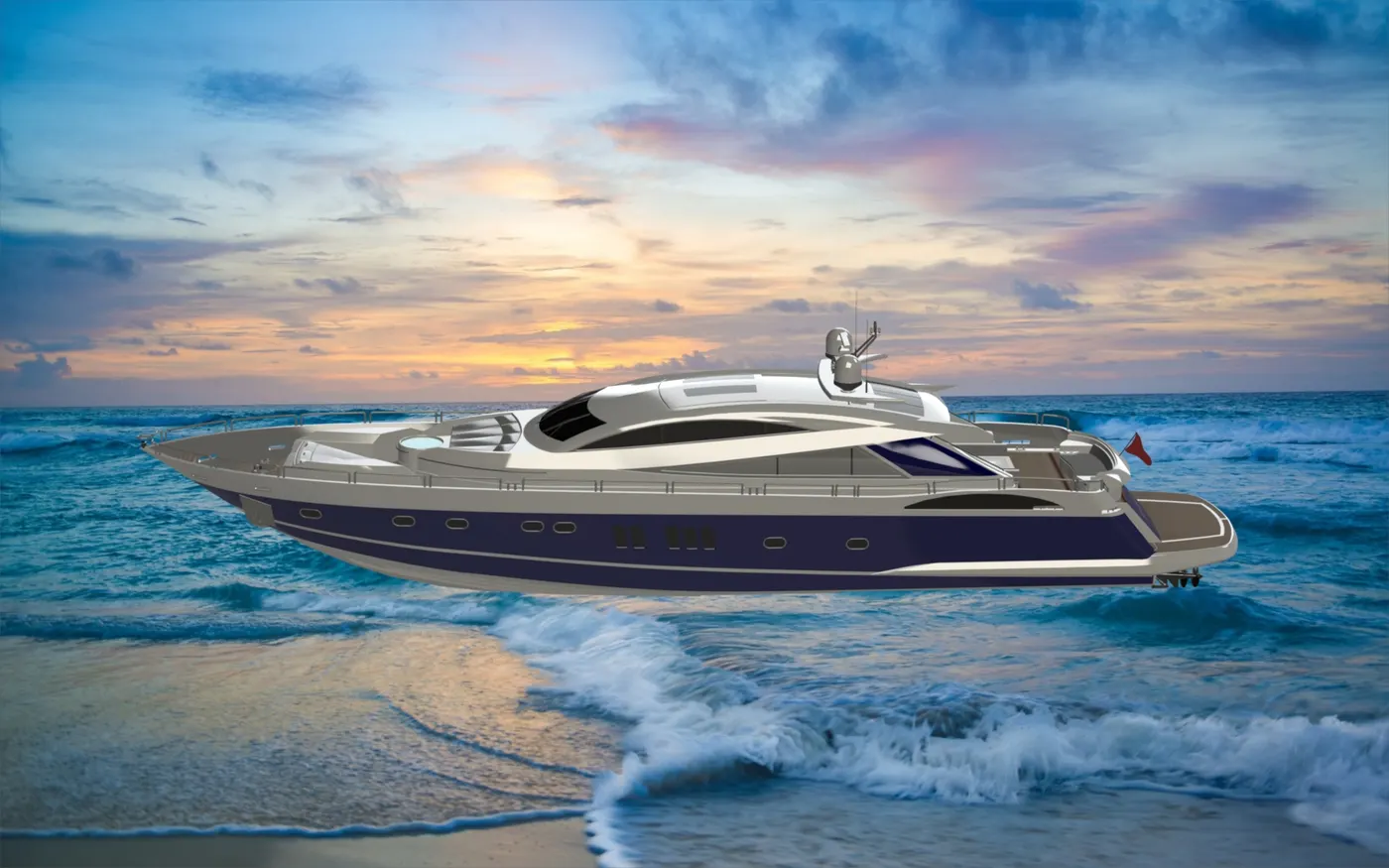
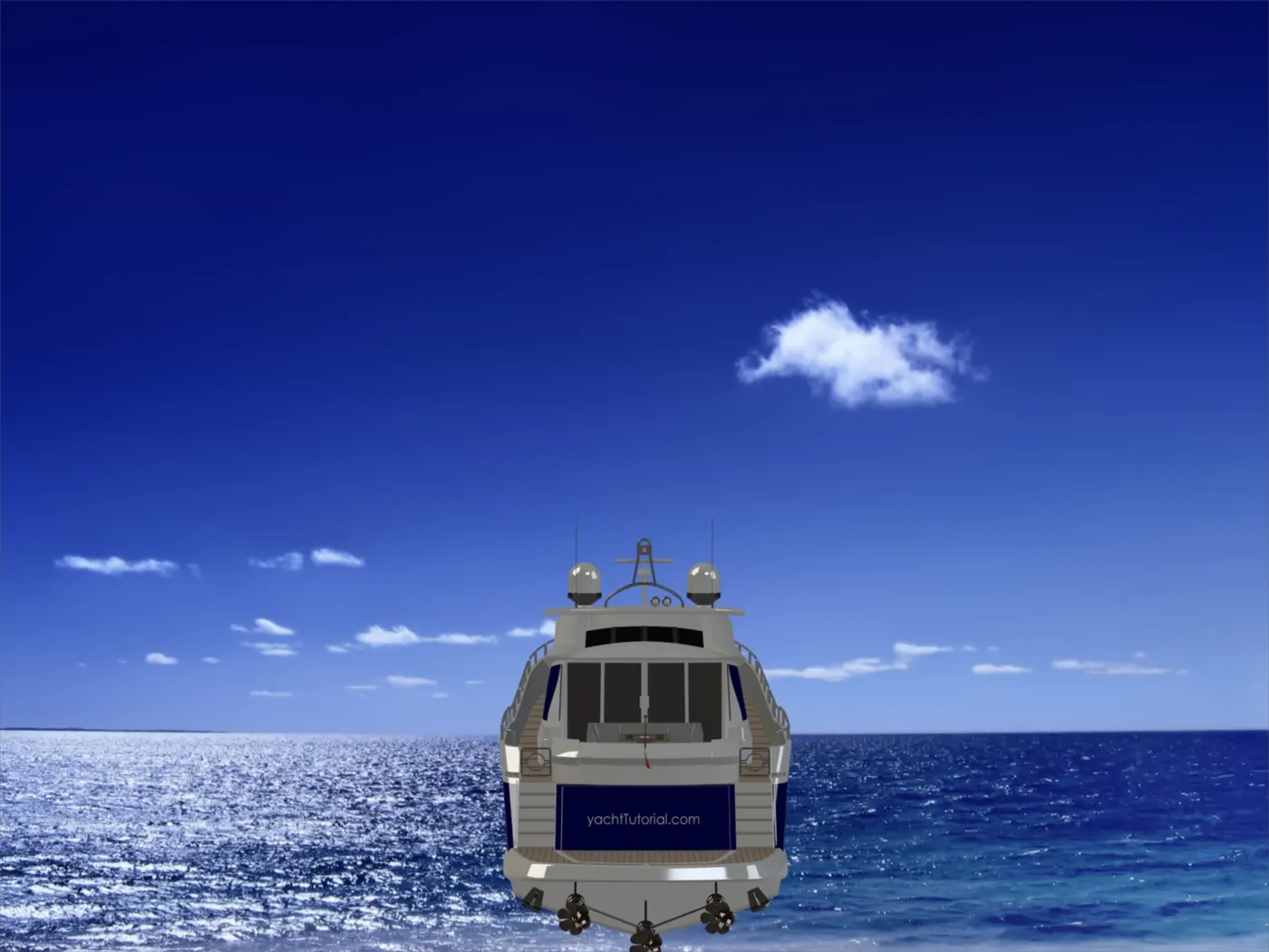
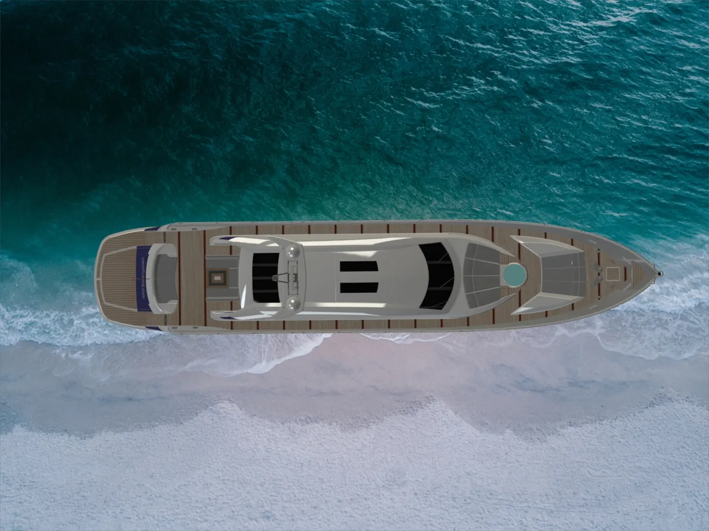
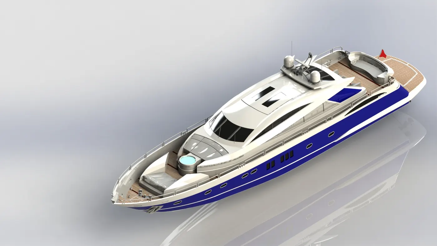
This report involves in the design, assembly, and rendering of the Sunseeker Predator Yacht Model, that has the beautiful look and Power vessel used for pleasure and racing. It has that superstructure and a garage for the vehicle. The yacht is designed and assembled in Solidworks 2018 and rendered using Solidworks Visualize 2018 and decals are fixed with the Photoview 360 to give a realistic look.
MODELLING
The Yacht is built through the feature-based surface and solid modeling features and consists of the following components,
- Propeller
- Radar
- Hull
- Garage Door
- Front Seat
- Middle Seat
- Rear Seat
- Super Structure
- Radar Mast
PROPELLER
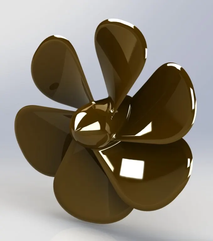
A propeller is a device with a rotating hub and radiating blades that are set at a pitch to form a helical spiral, that, when rotated, performs an action that is similar to Archimedes' screw. It transforms rotational power into linear thrust by acting upon a working fluid, such as water or air.
Tools/Features:
- Revolve
- Cut Extrude
- Surface Loft
- Fillet
- Circular Pattern
Procedure
- A closed full defined sketch is drawn with the help of a line tool and spline
- Then it is revolved to form a solid body
- The loft is used to draw the fins of the propeller
- The fine is filleted
- Cut extrude is used to form a hole on one side
- The circular pattern is used to pattern the fins over a circular object
RADAR
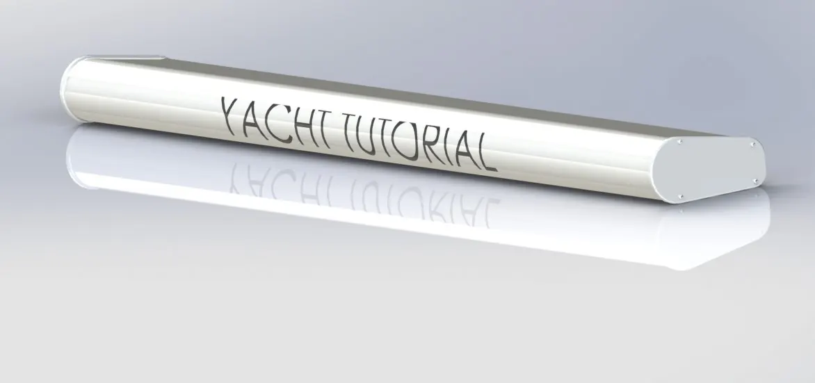
Radar is a vital navigation component for safety at sea and near the shore. Captains need to be able to maneuver their ships within feet in the worst of conditions and to be able to navigate "blind" when there is no visibility at night or due to bad weather.
Tools/Features:
- Extrude
- Cut Extrude
- Fillet
- Mirror
- Sketch Driven Pattern
- Split Line
Procedure
- A closed sketch is drawn and it is extruded then fillet is applied on the edges
- An offset is created on the one side and it is extruded
- To draw a nut first it is extruded and it is extrude cut to form a single nut
- Sketch pattern is used to pattern the nut
- The fillet is applied on the edges
- The bodies are mirrored concerning the plane
- Text is drawn with the help of split line
HULL
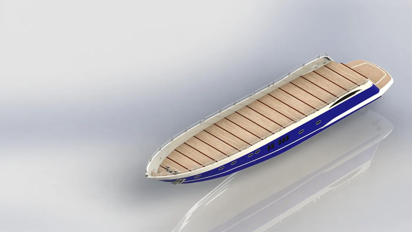
The hull of a ship is the most notable structural entity of the ship. To define the hull, it can be said that it is the watertight enclosure of the ship, which protects the cargo, machinery, and accommodation spaces of the ship from the weather, flooding, and structural damage.
Tools/Features:
- Project Curve
- Composite Curve
- Surface Loft
- Surface Extend
- Surface Trim
- Surface Fill
- Surface Knit
- Shell
- Boss- Extrude
- Cut Extrude
- Swept Boss
- Revolve Boss
- Dome
- Curve Pattern
- Linear Pattern
- Fillet
- Chamfer
- Mirror
- Split
Procedure
- First, the blueprint set up is opened and save as an option is used to a new part in the blueprint
- first, the outer surface is done with the help of surface tools like a surface loft, surface trim, surface extrude, surface knit surface fill
- then shell icon is used to make shell
- fillet chamfer is used at the edges
- the upper part is made by extrude boss cut extrude
- windows are made by cut extrude
- railings are designed by sweep option
- steps are designed at the end of the hub by cut extrude and boss extrude
- the propeller shaft is designed by the revolve option
- the split icon is used to split the part to form like a garage then it is saved in another file for further use
- mirror icon is used to mirror the bodies
- then separate decals are added to the surfaces
- the combine is used to combine the whole part into a single part
- the deck surface is used so that it can be taken as a reference to draw the other parts
GARAGE DOOR
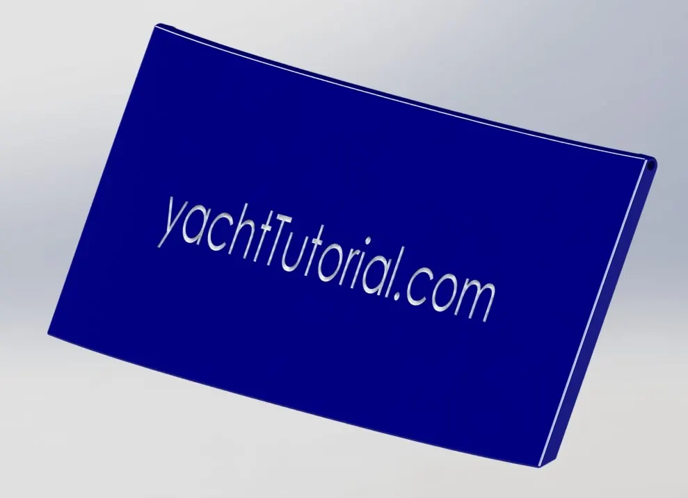
A Garage door is placed at the backside of the hull part, where either it can open manually or by an electric motor. Garage doors are frequently large enough to accommodate automobiles and other vehicles. Small garage doors may be made in a single panel that tilts up and back across the garage ceiling.
Tools/Features:
- Split
- Shell
- Text
Procedure
- The garage that is separated are cut extrude
- Then filleted on the outer edge
- A hole is created in one end by cut extrude
- Mirror to form a door
- Then cut extrude is used to cut in the garage door like an alphabets
The Garage door is constructed from the solid body cut from the hull model. Here the extra solids were just removed and shelled. A shaft hole is given for the rotation. The text is done in the garage door.
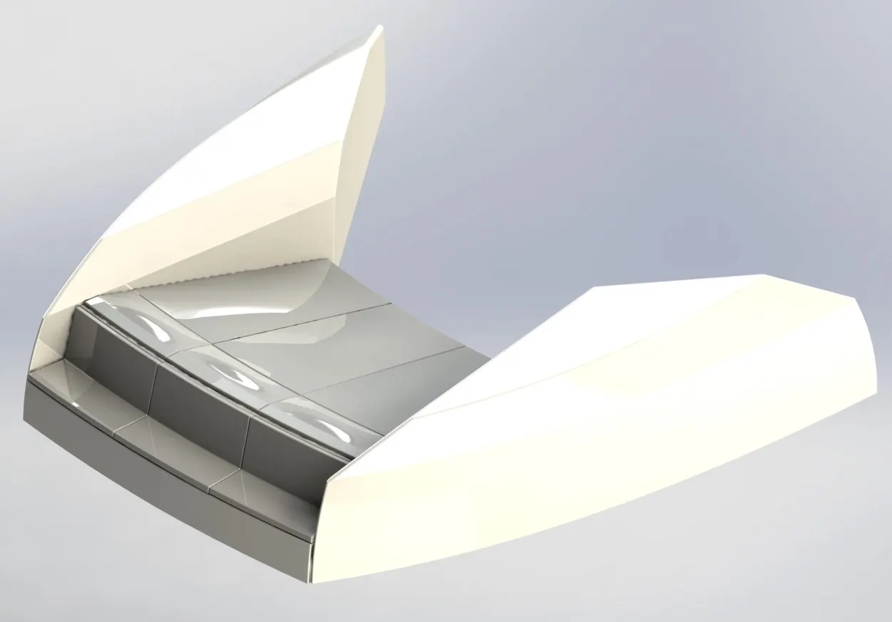
FRONT SEAT
The Front Seat is placed at front of the hull part which is placed with the pillow and bed with good comfort.
Tools/Features:
- Project Curve
- Swept Surface
- Loft Surface
- Ruled Surface
- Surface Extend
- Surface Knit
- Extrude
- Mirror
- Cut Extrude
- Fillet
- Chamfer.
Procedure
- First, the blueprint set up is opened and save as an option is used to a new part with the blueprint
- Insert part is used to insert the surface from the hull
- The designing is fully made with the surface options
- Revolve option is used to form the seat
- These seat edges are filleted
- Dome option is used to see the seat realistic
- Cut extrude is used to separate the seats
- The fillet is used at the corners
- A mirror is used to mirror the bodies
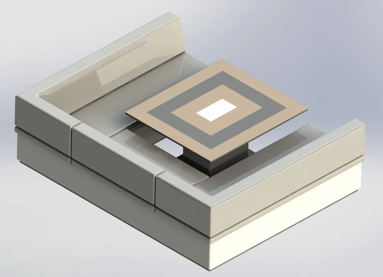
MIDDLE SEAT
Middle Seat is placed at the rear side of the superstructure with the center table and it is made with the good bed part.
Tools/Features:
- Extrude
- Surface Offset
- Cut Extrude
- Fillet
Procedure
- First, the blueprint set up is opened and save as an option is used to a new part with the blueprint
- Insert part is used to insert the surface from the hull
- Boss extrude is used to draw the stand of the seat
- Another bass extrude is used to draw the next part of the seat
- Another extrude is used to make the lower part of the seat
- Another extrude is used to do the sliding path of the seat
- Then the sliding is done by using a chamfer
- The fillet is applied to all the edges
- The mirror is applied to mirror the bodies
- Then the table in the center is designed by extruding and extrude cut
- The fillet is applied to all the edges
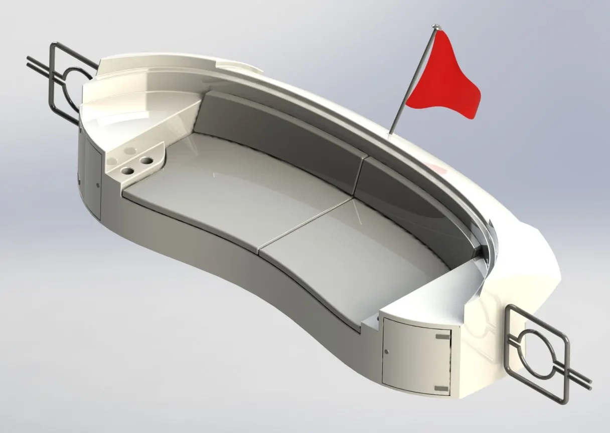
REAR SEAT
The rear seat is also placed at the rear part of the hull part and is attached to the bed and it is attached with the flag and gate.
Tools/Features:
- Curves
- Surface Loft
- Surface Rule
- Surface Knit
- Extrude
- Mirror
- Cut Extrude
- Pattern
- Swept Boss
Procedure
- First, the blueprint set up is opened and save as an option is used to a new part with the blueprint
- Insert part is used to insert the surface from the hull
- The designing is fully made in the surface
- Mainly all the surface options are used in these to form a rear bed
- Extrude option is used to make the pillows
- A chamfer is used in the pillows to make like an angle
- Sweep is used in the side of the bed to form like a steel rod
- A mirror is used to mirror the bodies
- Revolve is used to make the flag stand at the back
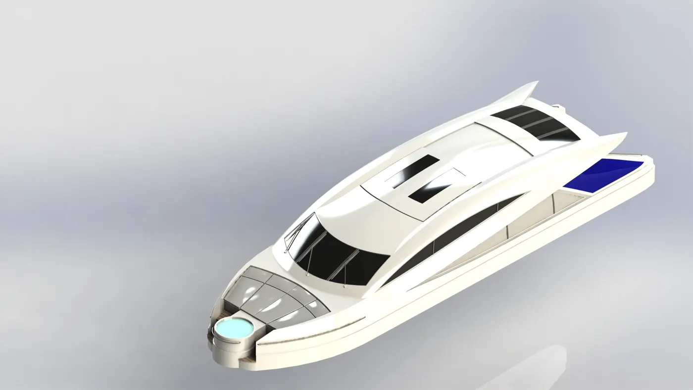
SUPERSTRUCTURE
A superstructure is an extended construction of any building or platform that rises above the rest of the building or platform distinctly. The word comes from a combination of two Latin words, the Latin prefix ‘super’ means also or above or more than, whereas the stem word ‘structure’ means to build or to heap up. Thus, superstructure means to add construction to an already existing structure. In ships, this is the name given to the part of the ship that emerges from the deck.
Tools/Features:
- Curve
- Surface Sweep
- Surface Rule
- Surface Extend
- Surface Extrude
- Surface Trim
- Surface Fill
- Surface Knit
- Offset Surface
- Sweep base
- Extrude Cut
- Extrude Boss
- Fillet
- Chamfer
- Delete face
- Mirror
Procedure
- First, the blueprint set up is opened and save as an option is used to a new part with the blueprint
- Insert part is used to insert the surface from the hull
- The surface option is used to design the outer surface of the superstructure
- Then it is made to the solid body by the surface knit option
- The surface knit option is again and after completion of the surface
- Cut extrude is used to cut the windows, doors
- Boss extrude is used to make the steel rod in the windows
- Extrude is also used to make handlebars in the door
- Sweep is used to make rounded steel rods
RADARMAST
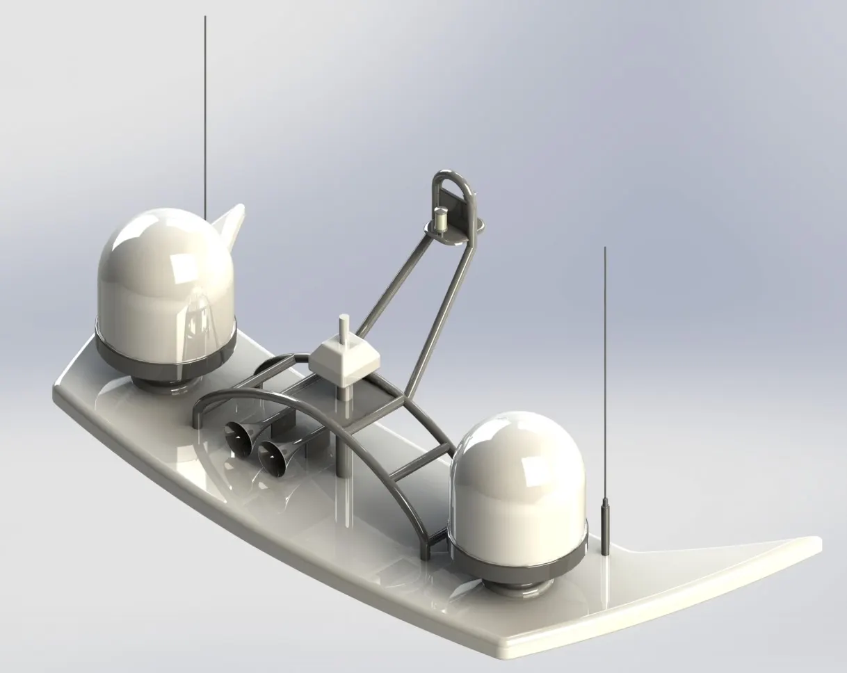
Marine radars are X band or S-band radars on ships, used to detect other ships and land obstacles, to provide bearing and distance for collision avoidance and navigation at sea. They are electronic navigation instruments that use a rotating antenna to sweep a narrow beam of microwaves around the water surface surrounding the ship to the horizon, detecting targets by microwaves reflected from them, generating a picture of the ship's surroundings on a display screen.
Tools/Features:
- Extrude
- Revolve
- Cut Extrude
- Sweep Surface
- Fillet
- Chamfer
Procedure
- First, the blueprint set up is opened and save as an option is used to a new part with the blueprint
- Insert part is used to insert the surface from the superstructure
- Boss extrude is used to make the surface for the radar mast
- The fillet is applied to all the edges
- Revolve is used to make a radar at the surface
- Boss extrude is used to make an antenna
- Sweep is used to make steel rods
- Boss extrude is used to make a stand for the radar
- A mirror is used to mirror the bodies
- Revolve, dome, the shell is used to make a horn
- Boss extrude is used to connect the horn with the surface
ASSEMBLY
Hull is the first component inserted into the assembly model and fixed concerning the planes. Then the components are inserted one by one into the assembly section and relations with the planes made them place directly in the place where they are meant to be.
The midplane of the hull is used for all the components that are inserted except the propeller. The garage door is made concentric with the shaft kept for it and the radar is also mad concentric with the radar mast as they are the rotating components. Also, the 3 propellers are made concentric with the hull model as they are also the rotating parts.
Thus, the garage door, radar, and propeller are underdefined in the assembly tree, and all other parts are made coincident with the hull surface.
Assembly procedure
- Take the hull and click in the window to fix it
- Take the superstructure and click in the window to fix it
- Take the front seat, mid seat and click in the window to fix it
- Take the radar mast and click in the window to fix it
- Take the garage door and make the coincident mate concentric mate to fix it
- Take the back seat and use distance mate and coincidence mate to fix it
- Take the propeller to use concentric and coincident mate to fix it
- Take the radar use the concentric and coincident mate to fix it
RENDERING
The final assembly model is rendered using Visualize and Photoview 360 suitable decals for the hull and stairs. This rendered yacht is used to give a realistic look with the environment .