Study of Power converters and Power electronics of electric vehicles.
Aim: To study Power converters and Power electronics of electric vehicles.
Objectives:
01.
To study power electronics circuits and losses occuring in power electronics circuits at practice.
02. A.
To develop a Simulink model for generating pulses for a simple power converter circuit. (Hint: Blocks : sine wave,carrier wave,relationaloperator,scope)
02. B.
Simulate a simple power converter circuit (Default) with the above results.
03.
To study VFD and Vector control drive for induction motor in EV application.
Introduction:
What is power electronics?
Power electronics is the branch of electrical engineering that deals with the processing of high voltages and currents to deliver power that supports a variety of needs.
From household electronics to equipment in space applications, these areas all need stable and reliable electric power with the desired specifications. Power supply in one form is processed using power semiconductor switches and control mechanisms to another form, supplying a regulated and controlled power. While switched-mode power supplies are a common application of power electronics where power density, reliability, and efficiency are of prime importance, motor control is gearing up with more electrification in transportation systems. Precise control and efficiency are key characteristics for power control applications. The study of power electronics is thus multidisciplinary, involving semiconductor physics, electrical motors, mechanical actuators, electromagnetic devices, control systems, and so on.
What is power converter?
A power converter is an electrical circuit that changes the electric energy from one form into the desired form optimized for the specific load. A converter may do one or more functions and give an output that differs from the input. It is used to increase or decrease the magnitude of the input voltage, invert polarity, or produce several output voltages of either the same polarity with the input, different polarity, or mixed polarities such as in the computer power supply unit.
What is Variable Frequency Drive?
A Variable Frequency Drive (VFD) or Adjustable Frequency Drive (AFD), Variable Speed Drive (VSD), or Inverter Drive is a type of motor drive used in electro-mechanical drive systems to control AC motor speed and torque by varying motor input frequency and voltage.
VFDs are used in applications ranging from small appliances to large compressors. About 25% of the world's electrical energy is consumed by electric motors in industrial applications. Systems using VFDs can be more efficient than those using throttling control of fluid flow, such as in systems with pumps and damper control for fans. However, the global market penetration for all applications of VFDs is relatively small.
What is Vector Control Drive?
Vector control, also called field oriented control (FOC), is a variable-control drive (VFD) control method in which the stator currents of a three-phase AC or Brushless DC electric motor, are identified as two orthogonal components that can be visualized with a vector. One component defines the magnetic flux of the motor, the other the torque. The control system of the drive calculates the corresponding current component references from the flux and torque references given by the drive's speed control. Typically proportional-integral controllers are used to keep the measured current components at their reference values. The pulse-width modulation of the variable-frequency drive defines the transistor switching according to the stator voltage references that are the output of the PI current controllers.
FOC is used to control AC synchronous and induction motors. It was originally developed for high-performance motor applications that are required to operate smoothly over the full speed range, generate full torque at zero speed, and have high dynamic performance including fast acceleration and deceleration. However, it is becoming increasingly attractive for lower performance applications as well due to FOC's motor size, cost and power consumption reduction superiority. It is expected that with increasing computational power of the microprocessors it will eventually nearly universally displace single-variable scaler volts-per-Herts (V/f) control.
Problem Statement:
01.
Why power electronics circuits are efficient? In practice, which types of losses occur in power electronics circuits?
02. A.
Develop a Simulink model for generating pulses for a simple power converter circuit? (Hint: Blocks : sine wave,carrier wave,relationaloperator,scope)
02. B.
Simulate a simple power converter circuit (Default) with the above results.
03.
Explain the difference between VFD and Vector control drive. Can we use VFD method for induction motor in EV application?
Solution:
01.
Why power electronics circuits are efficient? In practice, which types of losses occur in power electronics circuits?
Power electronics circuits are efficient because:
Flexibity in operation.Highly effieint due to low losses in power semiconductor devices.Automization is possible.Low installation cost, long life and less maintenance due to absence of any moving parts.Fast dynamic response compared to electromechanical converter systems.High reliability.Small in size and less weight.Easy to install.
Losses occuring in power electronic circuits are as follows:
Conduction Losses:
Conduction losses are simply the product of the current flowing through a switch or diode when it is forward biased (i.e. – turned on) and the voltage drop across it. The problem is determining what the actual voltage drop is at any given time, because this changes with temperature and current. Bipolar transistors (including IGBTs) and Schottky diodes (including SiC types) behave like a diode in series with a small resistance when forward biased. As with all diodes, there is a minimum forward voltage that must be applied before conduction occurs, and this forward drop can span the range of 0.3 V for a low-voltage Schottky diode to 2.2 V for a 1,700 V IGBT or SiC diode. The temperature coefficient of the diode is also negative (typically -2 mV / ° C), but that of the effective series resistance can be positive or negative depending on the device and specific construction. MOSFETs, in contrast, behave like a simple resistor when turned on, albeit one with such a strong positive temperature coefficient that on-resistance, RDS[on], typically doubles going from 25° C to 125° C. Regardless, you can get a reasonable first-pass estimate of the effect on-state drop will have on efficiency by simply subtracting the worst-case datasheet value from the supply voltage, keeping in mind that bridges (including the half-bridges in inverters) put two devices in series. So an inverter using IGBTs that drop 1.6 V will subtract 3.2 V from the supply, and if the supply is 320 V, that cuts efficiency by one percentage point right there.
Switching Losses:
Switching losses occur when the device is transitioning from the blocking state to the conducting state and vice-versa. This interval is characterized by a significant voltage across its terminals and a significant current through it. The energy dissipated in each transition needs to be multiplied by the frequency to obtain the switching losses.Conduction losses occur when the device is in full conduction. The current in the device is whatever is required by the circuit and the voltage at its terminals is the voltage drop due to the device itself. These losses are in direct relationship with the duty cycle.
02. A.
Develop a Simulink model for generating pulses for a simple power converter circuit? (Hint: Blocks : sine wave,carrier wave,relationaloperator,scope)
Simulink Model for generating pulses.
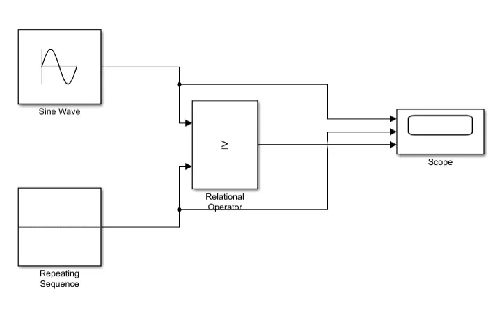
Fig01: Simulink model for generating pulses.
Above figure01 shows the model for generating pulses which are fed as the input signal to power converter so that power converter can perform it's operation conviniently to meet the speed-torque requirements of the vehicle. Sine wave block is used as the feedback signal from the throttle pedal and it is compared to the very last battery signal sent to the vehicle. And accordingly the pulse is generated to fetch more battery current for increase in speed-torque requirements or to minimize the rate of flow of current from the battery to lower the speed-torque requirements.
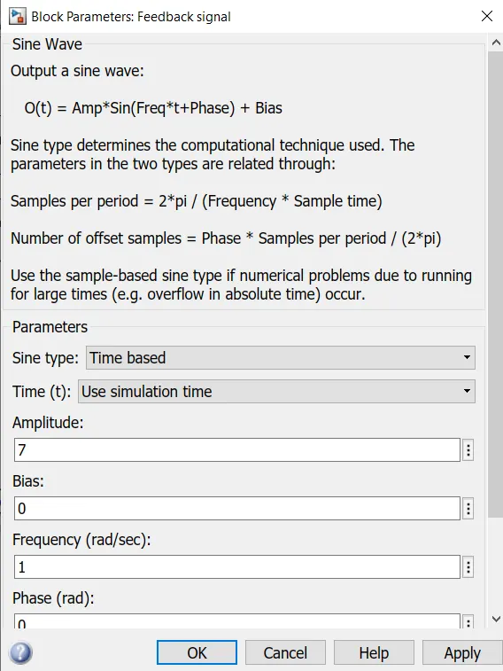
Fig02: Sine wave block parameters.
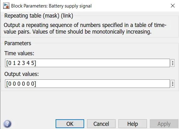
Fig03: Repeating sequence block and it's parameters.
To generate the regular DC signal repeating sequence block is used. And it's parameters are set as shown in figure03.
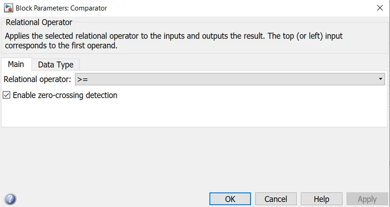
Fig04: Relational operator block and it's parameters.
Relational operator block is used to compare the feedback signal and the battery signal and to generate the pulse which further is sent to the power converter for further process.
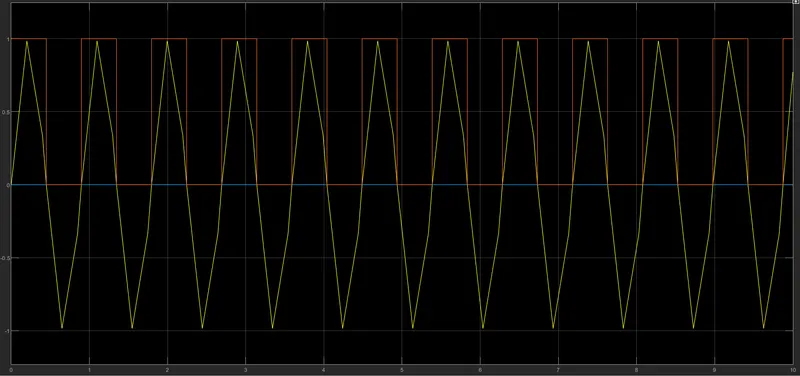
Fig05: Results for the simulink model of generating pulses.
Above figure05 shows the results in which the sine wave (feedback signal: yellow line) is compared with the battery signal (DC: blue line) and whenever the DC signal is less than the feedback signal the pulse (red line) is generated and accordingly the converter will change the position of the switch to cope up with the power requirements.
02. B.
Simulate a simple power converter circuit (Default) with the above results.
DC to DC power converter using generated pulses as a signal.
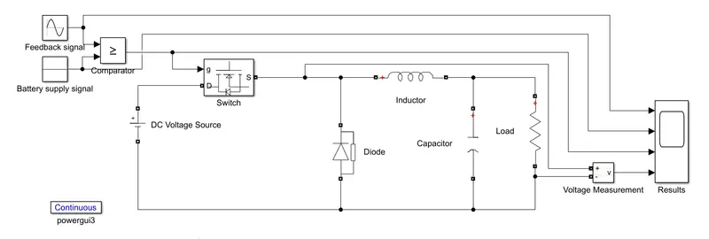
Fig06: Buck converter using the generating pulses model.
A buck converter (Step down converter) is a DC to DC power converter which steps down voltage (while drawing less average current) from its input (supply) to its output (load). It is a class of switched-mode power supply (SMPS) typically containing at least two semiconductors (a diode and a transistor, although modern buck converters frequently replace the diode with a second transistor used for synchronous rectification) and at least one energy storage element, a capacitor, inductor, or the two in combination. To reduce voltage ripple, filters made of capacitors (sometimes in combination with inductors) are normally added to such a converter's output (load-side filter) and input (supply-side filter).
Switching converters (such as buck converters) provide much greater power efficiency as DC-to-DC converters than linear regulators, which are simpler circuits that lower voltages by dissipating power as heat.
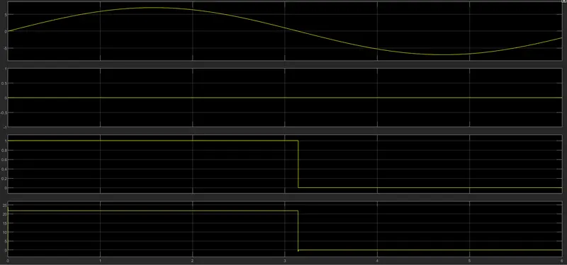
Fig07: Results for Buck converter using the generating pulses model.
First graph shows the results for the feedback signal.
second graph shows the results for the very last DC output of the battery.
Third graph shows the results for the generated pulses by the relational operator.
Fourth graph shows the results for the DC suppply of the battery according to the pulse signal received by the converter.
For fourth graph shows the pulse was generated to fetch more current from the battery because of lower magnitude of the carrier signal compared to the feedback signal. Thus the value of the voltage wave is 24 for the first instance where the magnitude of the the carrier signal is lower when compared to the feedback signal.
And the for second instance it's value gets reduced to zero. Where the magnitude of the the carrier signal is higher when compared to the feedback signal.
03.
Explain the difference between VFD and Vector control drive. Can we use VFD method for induction motor in EV application?
As far as we know all variable frequency drives with vector control can also be run with just V/F control.

A drive in vector control mode has several tuning parameters to increase or decrease motor performance. With factory default parameters a VFD in vector mode will have higher performance than a drive in V/F mode. Sort of like a "sport or racing" computer option in a modern automobile.

Depending on the application using vector control can use a lot more power. If you have a rapidly surging load the vector may be really struggling to keep the speed constant while a variable frequency drive in V/F mode never notices the speed change. If the application has a steady mid-range speed and load or has a slow rate of change a vector and V/F may be very close in amp draw.

If you have an application where you need the vector for starting or stopping quickly but you are using a lot of current at speed you can change vector parameters to reduce the current. In some applications it is cheaper to oversize a V/F drive to get starting or stopping torque if you don't need precise speed control.
The fact is, in the practice, V/f is considered by many the better choice for fan loads, but I see few reasons why V/f approach could result in better efficiency.

One reason could be that, since it doesn't try to regulate anything, practically it can't oscillate due to weak stability, although oscillations may still occur (It has been noted that, a heavily vibrating torque measurement on a fan driven by a V/f variable frequency drive).
Another could be that, while non-linear V/f curves (suitable to non-linear loads as fans) are quite common, the same is not done for the flux reference (magnitude) in vector control.
And, of course, the few parameters of a V/f control are far easier to tune than a vector scheme (which companies don't really share).

However, one interesting thing that can be done with vector control is, for slow dynamics applications, to automatically tune the flux reference to achieve a minimum loss control during the control operation. I don't think this would be possible with V/f.
Conclusion:
In this study we learnt the concept of the generating pulses and it's simulation incoporated with power converter using simulink. Also we learnt the comparision of VFD with the VCD.