Study of DC motor and it's applications in 'The Four-Quadrant Chopper DC Drive’ and 'The Two-Quadrant chopper'.
Aim:
Study of DC motor and it's applications in 'The Four-Quadrant Chopper DC Drive’ and 'The Two-Quadrant chopper'.
Objectives:
1.
A. To study a MATLAB demo model named ‘Speed control of a DC motor using BJT H-bridge’.
B. Observe and study the armature current shoot-up from the scope results.
C. Refer to the help section and study the ‘The Four-Quadrant Chopper DC Drive (DC7) block’. Compare it with the H-bridge model.
2. To study a 2-quadrant chopper using simulink & the working of the same with the relevant results. (Refer to article - Multiquadrant operation of motor )
3. To study the operation of BLDC motor.
Introduction:
Electric Motors:
What is motor?
Motor is a machine that converts the electrical energy into mechanical enegy. Now there are two types of supplies as electrical energy. First is Alternating current (AC) and second is Direct current (DC). Both currents have there own merits and based on the vehicle load requirements we have to use a specified type of motor which will meet the load requirements of the vehicle. It can be a AC motor or motor.
The motor which converts the Direct current (Electrical energy) into mechanical energy is called as DC motor.
The motor which converts the Alternating current (Electrical energy) into mechanical energy is called as AC motor.
Power Switches:
I. Power Bi-Polar Junction Transistors (PBJTs):
Power Bi-polar Junction Transistors are semi-conductor switches used in electric circuits to control and moniter the electric signals from the source which further are forwarded to electromechanical or mechanical systems.
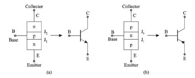
Fig01: Symbol of PBJTs (a) npn and (b) pnp
It consists of two sides control side and power side.Control side consists of one terminal and power side consists of two terminals.Control terminal is one of the reference with power terminalCollector (C), Emitter (E) and Base (B) are three terminals of the transistor.Power terminals are connected between collector and emitter.Control signals are applied between base and emitter.Emitter serves as commom side between power side and control side.Collector and Emitter terminals are short circuited or open based on the base signal is given or not.If there is base signal to the emitter, emitter gets closed with controller.If there is no base signal to the emitter, emitter and controller remains open.Voltage and current are contradictory in both open and closed conditions.In open condition there is no current but voltage is present across the switch.Whereas in closed condition there remains no voltage across the switch but current will flow through it.pnp and npn transistor is categorised depending upon it's construction.In pnp type the emitter terminal is connected to positive terminal of the battery whereas in the npn type the emitter terminal is connected to the negative terminal of the battery.
II. Metal Oxide Semi-conductors Field Effect Transistors (MOSFETs):
Metal Oxide Semi-conductor Field Effect Transistors switches are used in electric circuits to control and moniter the electric signals from the source which further are forwarded to electromechanical or mechanical systems.
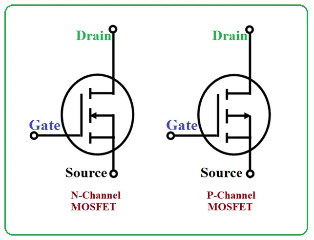
Fig02: Symbols of MOSFETs (a) n channel and (b) p channel.
It consists of two sides control side and power side.Control side consists of one terminal and power side consists of two terminals.Control terminal is one of the reference with power terminalDrain (D), Source (S) and Gate (G) are three terminals of the transistor.Power terminals are connected between Drain and Source.Control signals are applied between Gate and Source.Source serves as commom side between power side and control side.Drain and Source terminals are short circuited or open based on the gate signal is given or not.If there is gate signal to the Source, Source gets closed with Drain.If there is no gate signal to the Source, Source and Drain remains open.Fundamental of the MOSFET is same as that of power BJT except this switch is operated through effect of field whereas BJT is operated through effect of the current.Therefore only if there is voltage across Gate and Source terminals switch is operated.Both PBJTs and MOSFETs are the enhanced versions of the transistors.MOSFETs are operated at very high switching frequency.n channel and p channel are categorised depending upon it's construction.In p channel type the emitter source is connected to negative terminal of the battery whereas in the n channel type the source terminal is connected to the positive terminal of the battery.
III. Insulated Gate Bi-polar Junction Transistor (IGBJTs):
Insulated Gate Bi-polar Junction Transistors are semi-conductor switches used in electric circuits to control and moniter the electric signals from the source which further are forwarded to electromechanical or mechanical systems.
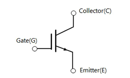
Fig03: Symbol of IGBT.
It consists of two sides control side and power side.Control side consists of one terminal and power side consists of two terminals.Control terminal is one of the reference with power terminalController (C), Emitter (E) and Gate (G) are three terminals of the transistor.Fundamental of the IGBJTs is same as that of PBJT icluding this switch is operated through effect of current.These are high power switches which means these switches has a very high load (voltage and current) carrying capacity.Mostly MOSFETs or IGBTs are used for EV applications.
Comparision of switches:
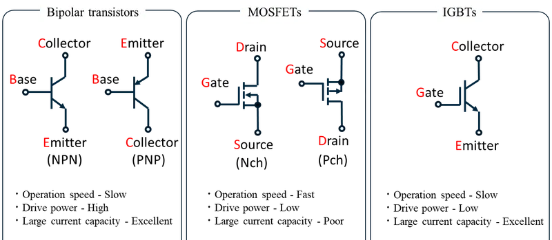
Fig04: Comparision of switches.
BJT H-Bridge:
As we studied that semi-conductor switches are used to control the power signals. So to control the the speed of the DC motor simply by controlling and governing the control signals. The combination of four such switches is used which when connected with help of wires to the DC motor, this whole circuit forms a structure like alphabet 'H' therefore called as BJT H bridge circuit to control the speed of DC motor.
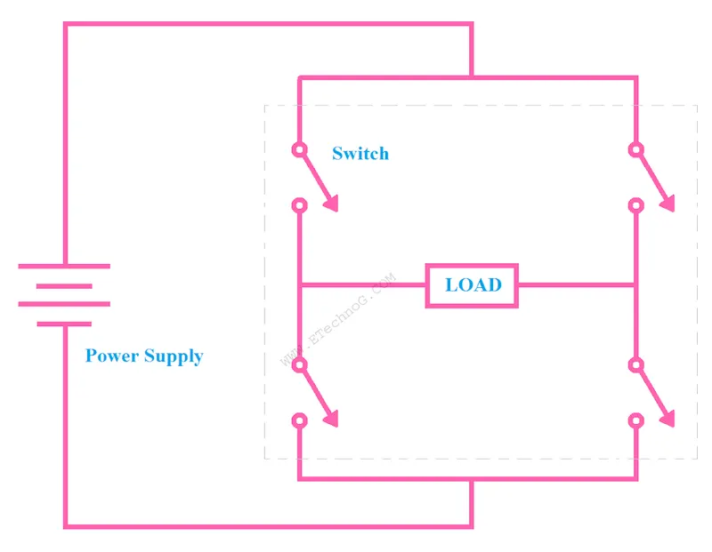
Fig05: BJT H bridge circuit.
Problem Statement:
1. A. Explain a MATLAB demo model named ‘Speed control of a DC motor using BJT H-bridge’.
B. Comment on the armature current shoot-up from the scope results.
C. Refer to the help section of ‘The Four-Quadrant Chopper DC Drive (DC7) block’. Compare it with the H-bridge model.
2. Develop a 2-quadrant chopper using simulink & explain the working of the same with the relevant results. (Refer to article - Multiquadrant operation of motor )
3. Explain in a brief about operation of BLDC motor.
Solution:
01. A.
Explain a MATLAB demo model named ‘Speed control of a DC motor using BJT H-bridge’.
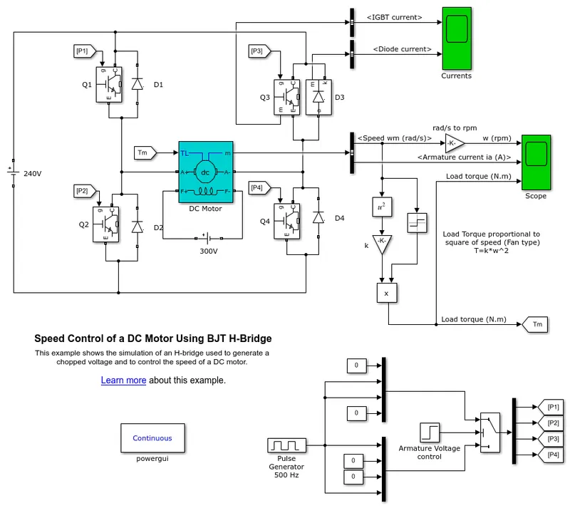
Fig06: ‘Speed control of a DC motor using BJT H-bridge’ of Matlab.
Here the DC voltage source of 240 volts is applied across the circuit.
Here total four numbers of BJTs (Bi-polar Junction Transistors) are used. But when we use BJTs for power switching applications they starts operating as IGBTs (Insulated Gate Bi-polar Junction Transistors).
Q1, Q2, Q3 and Q4 are the four IGBTs supplied with the input signals from the 'From Block' P1, P2, P3 and P4 respectively.
Each IGBT has it's own input signal which it receives from the 'From Block'.
The function of 'From Block' isto receive the signals from the goto tags of the specified tags.
To understand, How these input signals are generated we must study following circuitory first.
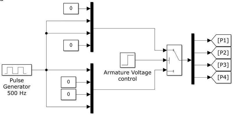
Fig07: Input Form Block circuit.
This circuit consists of Pulse Generator, Armature voltage control, Switch, Goto blocks, Multiplexers and Input constants to them.
The function of Pulse generator block isto generate a time based pulse where values of amplitude, period and pulse width (as per duty cycle) are entered based on vehicle load requirements. Here amplitude is taken as 1. This amplitude is given to both multiplexers and for each of them this amplitude is again sliced into two inputs as shown in figure.
In order to match the switching sequence of the BJTs Q1, Q2, Q3 and Q4. The connections of the constants and amplitude of the pulse must be done in specified manner.
The function of multiplexer isto multiples vector or scaler signals and the function of demultiplexer isto separate the vector or scaler signals.
The circuit consists of a switch. Switch has three input terminals say u1, u2 and u3. One output terminal o1. The operation of switch is simple. Port 1 and port 3 on input side are data ports and port 2 is the control port. If input signal satisfies the condition given to the port 2 than signal passes through the port 1 or else it will pass through port 3. For operation signals must be given in the sequence from left to right or from up towards down.
The signal to the control port of the switch is given by the 'Armature Voltage control'. The signal is nothing but the condition, if the condition is true the signal will flow through the data port 1 otherwise it will flow through the data port 3.
For Armature VoltageControl,
The 'Initial value' is set as '0' and 'Final value' is set as '1'. The 'Step time' is set as '0.5' seconds. That means for first 0.5 seconds the condition is true and for rest of 0.5 seconds the condition is not true.
For true condition the signals from the upper multiplexer are forwarded through the switch to all the 'Goto blocks' P1, P2, P3 and P4. And according to the input signals only P1 and P4 'Goto blocks' will get activated and carry the input signal towards their 'From blocks' P1 and P4.
If the condition is not true, the signals from the lower multiplexer are forwarded through the switch to all the 'Goto blocks' P1, P2, P3 and P4. And according to the input signals only P2 and P3 'Goto blocks' will get activated and carry the input signal towards their 'From blocks' P2 and P3.
Now, let's study the H-bridge circuit.
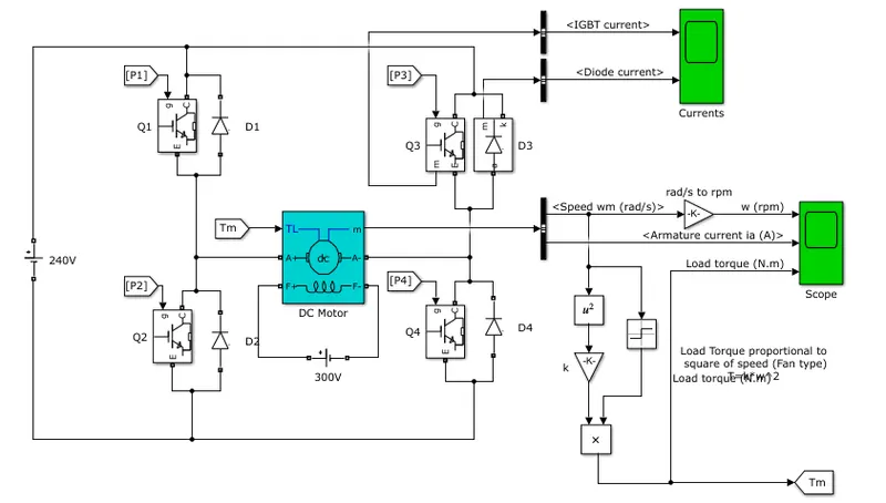
Fig08: Speed control of the DC motor using the BJT H-Brige circuit.
The H-bridge circuit consists of four BJTs Q1, Q2, Q3 and Q4. The Bipolar Junction Transistor (BJT) when used for power switching applications, operates as an IGBT. So we can also say that four IGBTs Q1, Q2, Q3 and Q4 are used.
The IGBT block does not simulate the gate current controlling the BJT or IGBT. The switch is controlled by a Simulink signals (1/0). Circuit also includes the DC motor preset model (5 HP 24V 1750 rpm).
The armature mean voltage can be varied from 0 to 240 V when the duty cycle (specified in the Pulse Generator block) is varied from 0 to 100%. In this case we had assumed duty cycle as 75%.
All the four transistors works in a such a way that, a chopped voltage and the control over speed of a DC motor is achived simply by switching action.While switching only of all four transistors are switched simultaneously: Q1 and Q4 or Q2 and Q3.
If Q1 and Q4 are in operation, a positive voltage is applied to the motor and diodes D2-D3 operate as free-wheeling diodes when Q1 and Q4 are switched off.
Similarly when Q2 and Q3 are in operation, a negative voltage is applied to the motor and diodes D1-D4 operate as free-wheeling diodes when Q2 and Q3 are switched off.
Since the duty cycle is 75% the average value of applied coltage can be calculated as follows:
For t = 01 second
`Vavg = ((Vb*Ton)+(Vb*Toff))/60`
`Vavg = ((240*45)+(00*15))/60`
Therefore,
Vavg = 180 volts.
At t= 0.5 sec, the armature voltage is suddenly reversed and the motor runs in the negative direction due to change in direction of the current.
A conversion of speed from rad/sec to rpm is held between the bus sector to scope using the converter block.
Further scope are used to generate plots of important parameters against the time (T).
01. B.
Comment on the armature current shoot-up from the scope results.
Following are the scope results for various important parameters against time.
a. Motor speed vs. Time:

Fig09: Motor speed vs. Time.
Above graph shows the plot of motor speed against time. Initially during starting of the motor speed remains zero and gradually increases as the supplied current reach it's peak magnitude gradully. As the current remains constant upto half of the time period the motor speed achives it's peak value and remains constant upto half of the time period. But as the current changes it's direction the motor starts running in reverse direction thus speed of the motor falls gradually to zero and gradually keeps falling to achieve it's maximum negative value (maximum speed of the motor when its moving in reverse direction).
b. Armature current vs. Time:

Fig10: Armature current vs. Time.
The connections for the current and the voltage are made through IGBTs and while switching ON and OFF of the switches (during transistion) the current and voltage are both contradictory to one another. As the value of currrent gradually decreases at very same time the value of voltage gradually increases and vice-versa. This results in the sudden rise and fall of the armature current during ON and OFF states of the switches. But once the switch is closed the value of current in the circuit remains constant thus it shows a straight line. The plot above the zero represents the plot during the forward direction of the current and the plot below the zero represents the plot during the reverse direction of the current.
c. Load Torque vs. Time:

Fig11: Load Torque vs. Time.
Initially as the current gradually increases the torque produced by the motor also increases gradually. And then it's magnitude remains constant as the value of current remains constant. But when motor starts running in reverse direction it's no more a torque producing device it's a torque consuming device this is the reason why plot gradually comes to zero and falls below zero and achieves it's maximum negative value which represents the maximum torque consume by the motor.
d. IGBT current vs. Time:
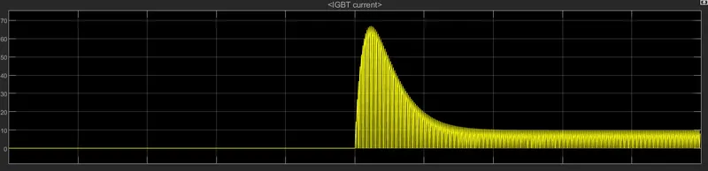
Fig12: IGBT current vs. Time.
Just after the half of the time period the switching of the IGBTs is done this results in maximum intake of current for IGBTs and some value of the IGBT current is maintained for the operation of Q2 and Q3 while the motor is running in reverse direction.
e. Diode current vs. Time:
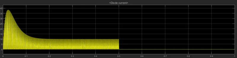
Fig13: Diode current vs. Time.
Diode current gradully increses in the beginning and gradually returns back to some value and then finally falls to zero because diodes D2-D3 operate as free-wheeling diodes when Q1 and Q4 are switched off.
01. C.
Refer to the help section of ‘The Four-Quadrant Chopper DC Drive (DC7) block’. Compare it with the H-bridge model.
Let's understand the Four Quadrant Operation of the DC motor:
When we say Four Quadrant operation of any DC motor drive it means, the motors operates in all four quadrants. As we know the motor operates in two modes Motoring and Braking. Depending upon nature of speed of and operation of the motor in specified quadrant, the modes can be further classified as Forward Motoring, Forward Braking, Reverse Motoring and Reverse Braking.
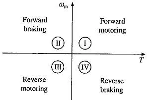
Fig14: Four-Quadrants of Chopper DC Drive (DC7).
Quadrant:I
In the beginning the voltage and current are in same direction.Here the motor produces the torque, therefore it's in motoring operation.Since the speed is positive it's called as Forward Motoring.
Quadrant:II
In second quadrant the direction of the current is changed keeping the voltage polarity constant.This is when we try to operate the motor in regenerative braking maode.In this quadrant the speed of the motor is positive whereas the torque is a negative value therefore it is called as Forward Braking.
Quadrant:III
In this quadrant the polarity and the direction of the current both are changed this results in rotation of the motor in opposite direction also the torque produced by the motor is negative but the work is consumed by the load.Since both speed and the torque both have negative values; the power is positive value.This operation is called Reverse Motoring.
Quadrant:IV
In this quadrant the polarity of the voltage is changed whereas the direction of the current is kept unchanged.This results in rotation of the motor in opposite direction and the torque produced is the positive value.Since this is a regenerative braking operation it's also called Reverse Braking.
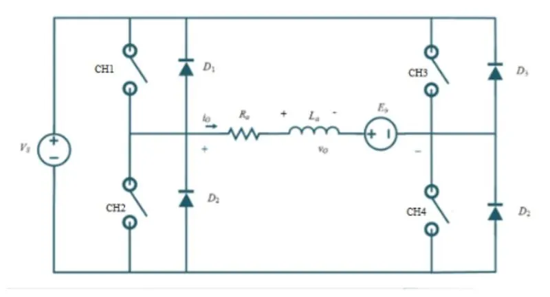
Fig15: Basic circuit diadram for Four-Quadrants of Chopper DC Drive.
For Quadrant-I:
Turning ON CH1:
When CH1 is operated, switches CH1 and CH2 conducts, output voltage and output current both are positives, power flows from source to load and inductor stores energy while the rotor rotates in the forward direction.
Turning OFF CH1:
When switch CH1 is turned OFF, switch CH4 and diode D2 conducts output current is positive and the output voltage becomes zero. An induction releases energy and using diode D2 freewheeling comes into action motor continues to rotate in forward direction hence, called forward motoring.
For Quadrant-II:
Turning ON CH2:
Switch Ch2 is operated so that switch CH2 and diode D4 conducts, output voltage is zero and Eb is responsible for the negative output current. Here machine behaves as a generator and inductor stores a energy.
Turning OFF CH2:
While switch CH2 turned OFF, diode D1 and diode D4conduts, output voltage becomes positive and the output current becomes negative. Inductor releases the energy by using diodes D1 and D4 where power flows from load to source and thus called as forward braking.
For Quadrant-III:
Turning ON CH3:
When CH3 is operated, switches CH3 and CH2 conducts. Both output voltage and current are negative values.Power flows from source to load and inductor stores energy therefore the motor rotates in reverse direction.
Turning OFF CH3:
When CH3 is turned OFF, switch CH2 and diode D4 conducts, output current is negative and the output voltage becomes zero. Inductor releases the energy diode D4 performs the freewheeling and motor runs in reverse direction, thus it is called reverse motoring.
For Quadrant-IV:
Turning ON CH4:
The polarity of back emf must be reversed. Let's assume that the motor is running in the reverse direction. Here switch CH4 operated, switches CH4 and D2 conducts, output voltage is zero and Eb is responsible for the positive output current. Thus machine behaves as a generator and inductor stores energy.
Turning OFF CH4:
When CH4 is turned OFF, diode D2 and diode D3 conducts, output voltage becomes negative and output current is positive. Inductor releases the energy using diodes D2 and D3. The flow of power is from load to source therefore it's callled as reverse braking.
The Four-Quadrant Chopper DC Drive (DC7) block
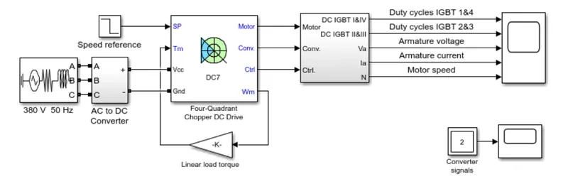
Fig16: The Four-Quadrant Chopper DC Drive (DC7) block.
The 200 HP DC motor is separately excited with a constant 150 V DC field voltage source. Thearmature voltage is provided by an IGBT converter controlled by two PI regulators. The converter is fed by a 515 V DC bus obtained by rectification of a 380 V AC 50 Hz voltage source.
In order to limit the DC bus voltage during dynamic braking mode, a braking chopper has been added between the diode rectifier and the DC7 block.
The first regulator is a speed regulator, followed by a current regulator. The speed regulator outputs the armature current reference (in p.u.) used by the current controller in order to obtain theelectromagnetic torque needed to reach the desired speed. The speed reference change rate follows acceleration and deceleration ramps in order to avoid sudden reference changes that could cause armature over-current and destabilize the system. The current regulator controls thearmature current by computing the appropriate duty ratios of the 5 kHz pulses of the four IGBT devices (Pulse Width Modulation).
For proper system behaviour, the instantaneous pulse values of IGBT devices 1 and 4 are opposite to those of IGBT devices 2 and 3. This generates the average armature voltage needed to obtain the desired armature current. In order to limit the amplitude of the current oscillations, a smoothing inductance is placed in series with the armature circuit.
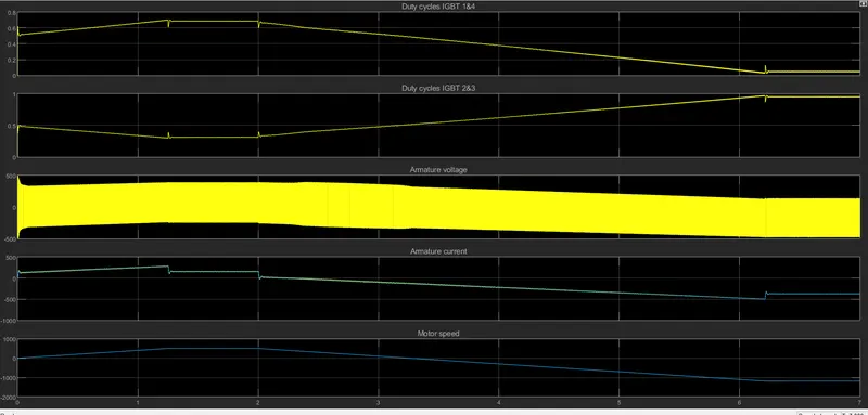
Fig17: Results for Four-Quadrant Chopper DC Drive (DC7) block.
Comparision of Four Quadrant Chopper DC drive and H-bridge:
The four quadrant chopper DC drive performs operation in all four quadrants. Forward motoring, Forward braking, Reverse motoring and Reverse braking are the operations carried out in quadrants I,II,III and IV respectively. All of these operations are carried out in mentioned sequence only and for that direction of current and the polarity of voltage is varied accordingly. Whereas in the H-bridge circuit the operations are carried out in only I and III quadrants. Forward motoring and Reverse are only two operations carried out in H-bride circuit.
In modern vehicle technology for charging of electrical vehicles H-bridge circuit is used and four quadrant circuit is used in industrial and commercial apllications.
The efiiciency is high and maintenance of the of DC chopper is less when compared to H-bridge.
The main drawback of the H-brdge circuit is that the regenerative braking is not possible in it where as in DC chopper circuit it is possible.
The most important aspect of the H-bridge circuit is that it can be used in the motor driver circuit. Suitable for compact design requirements therefore are used in robotics and it's apllications. Where as four quadrant DC chopper circuits are light in weight and are used in engine test loading systems.
2. To study a 2-quadrant chopper using simulink & the working of the same with the relevant results.
Let's study the Two Quadrant circuit first.
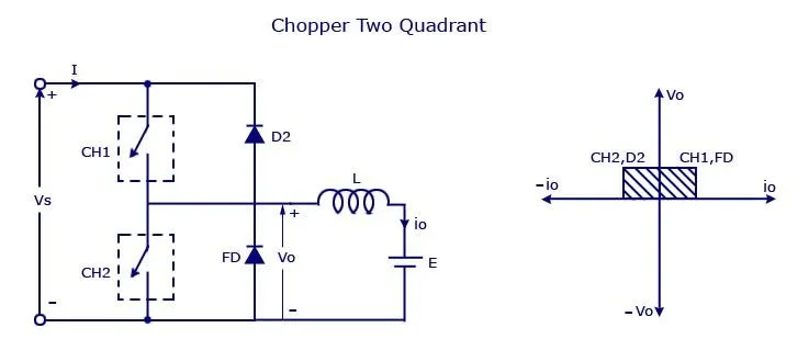
Fig18: Circuit diagram for Two-Quadrant DC chopper.
We'll always get a positive voltage output Vo as the freewheeling diode FD is present across the load. When the chopper CH1 is ON the current flows from source to load. The inductor stores energy. When CH1 is turned OFF the freewheeling diode starts conducting and the output voltage Vo will be equal to Vs. The direction of the load current Il will be reversed. The current Il will flow through the source. The load current will be negative when the CH2 is ON. The completes it's path through the diode D2.
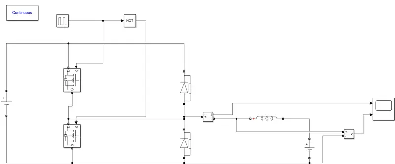
Fig19: Simulink model for Two-Quadrant DC chopper.
Simulink model: Two Quadrant circuit for DC chopper.
A DC voltage source of 96 volts is apllied across the circuit. Two MOSFETs are used for the switching action which are monitered by the signals produced by the NOT (logical operator) to avoid the operation of the both MOSFETs simultaneously to eleminate the risk of short-circuit. Pulse generator is used to generate the pulse of the required amplitude and time period. Further the circuit also consists of two diodes. One of which acts as a freewheeling diode. Series RLC Branch is used to define the load of the circuit. Where the value of the inductance is set to the default value. One more DC voltage source of 48 volts is applied at the end across the load which governs the circuit while CH2 is ON. Further the current and the voltage for the load are given to the scope to get the desired results.
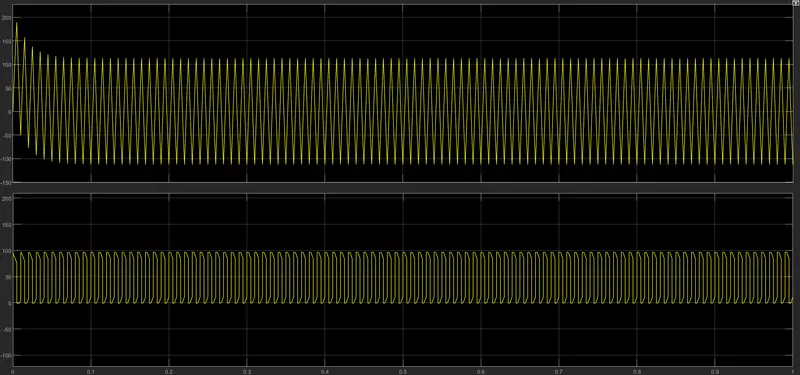
Fig20: Results for Two-Quadrant DC chopper.
First graph shows the results for current value against the time.
And second graph shows the results for current voltage against the time.
Current shows the positive and negative behaviour since the direction of the current is changed during the second half of the cycle.
Whereas the voltage shows the positive behaviour since it's polarity is kept constant although the value chages as per the operation of the circuit.
3. Explain in a brief about operation of BLDC motor.
Construction and working of Brushless DC motor:
Let's understand a bit about DC brushed motor first. A brushed DC motor has permanent magnets on the outerside of it's structure, with a spinning armature inside. The permanent magnets which are stationary on the outside are called as stator. The armature, which rotates and contains an electromagnet, is called as rotor.
In a brushed DC motor, the rotor spins 180-degrees when an electric current makes it's way to the armature. To go any further the poles of an electromagnet must flip. The brushes, as the rotor spins, makes contact with the stator, flipping the magnetic field and allowing the rotor to spin a full 360-degrees.
Now let's understand a bit about the construction of a brushless DC motor is essentially flipped inside out, eliminating the need for brushes to flip the electromagnetic field. In brushless DC motors, the permanent magnets are on the rotor and the electromagnets are on the stator. The charging of the electromagnets is done in stator to rotate the rotor in full 360-degrees.
In operation of the brushless DC motor the direction (clockwise or anti-clockwise) in which the resultant of the electromagnetic flux is generated will be the direction in which the motor will run. The stator consists of three poles say u,v and w.
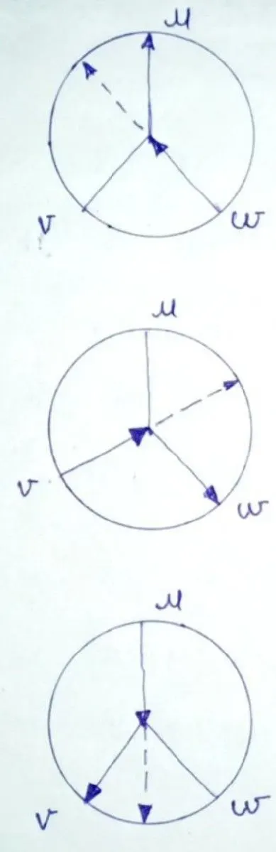
Fig21: First three positions of stator windings BLDC motor considering u phase as a reference.
For first position the current is entring from w pole and leaving from u pole.
For first position the current is entring from v pole and leaving from w pole.
For first position the current is entring from u pole and leaving from v pole.
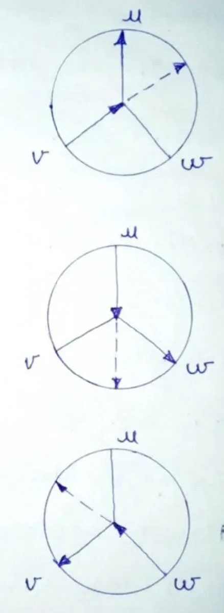
Fig22: Second three positions of stator windings BLDC motor considering u phase as a reference.
For first position the current is entring from v pole and leaving from u pole.
For first position the current is entring from u pole and leaving from w pole.
For first position the current is entring from w pole and leaving from v pole.
The dotted arrow shows the position of the resultant flux.
Clockwise direction of the motor means that resultant flux is generated clockwise direction by the vectors.
Inward direction of an arrow indicates the excitation of that particular pole which also indicates that current is flowing inwards through the pole. Whereas the outward direction of an arrow indicates that the current is flowing outward through that pole.
Each pole is maintained simultaneously for ON and OFF conditions keeping in mind one pole allows the inward flow of current while adjacent to it allows outward flow of current while the third one remains inactive.
This results in continuous change in posotion of the resultant flux which in turn rotates the rotor of the motor. The moment the rotor tries to catch and settle at the position of the resultant flux the flux changes it's position and this results in the continuous rotation of the rotor.
This is trapezoidal arrangement also called as six-step operation of DC motor.
Another arreangement is sinusidal arrangement the physical distribution of the windings is slightly changed.
All three phases are excited simultaneously such that resultant flux or rotation of the motor is attained in much smoother way compared to trapezoidal arrangement.
Another advantage of sinusidal arrangement is there is less repulsion in the value of the torque.
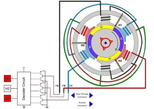
Fig23: Construction of brushless DC motor.
Three phases of the motor receives signal according to the activation of the Hall sensors H1,H2 and H3 which works in order of Hi, Off and Low. These hall sensors are connected to the motor with the help of inverter circuit. The red colour of the hall sensors shows that these sensors are activated. In order to provide the control signal to the hall sensors total six Power BJTs are employed for that particular operation which works in a specified sequence. Blue wire shows the return path whereas the red wire shows the positive path.
All these three wires black, red and blue are winded around the two poles which are exactly opposite to one another. The black one remains the idle for this particular step of opeartion. Phase with High signal takes current to the motor from the source wherreas the phase with low signal takes current from the motor to the source. While the phase with Off signal remains idle.
So in order to rotate the rotor of the motor we must shift the resultant of the flus continuously in required direction and the can be achieved by excitation of the all six poles of the motor (two opposite poles at a time) with the help of three phase windings which are governed by the hall sensors signals.
Conclusion:
In this study we learned about the MATLAB demo model named ‘Speed control of a DC motor using BJT H-bridge’. Where we studies the semi-conductor switches and their use in the H-bridge circuit to control the speed of DC motor. The parameters such as diode current, IGBT current, load torque, speed of motor and armature current are studied. Comparision of ‘The Four-Quadrant Chopper DC Drive (DC7) block’. is done with the H-bridge model based on thier construction, application and performance. We also learned about the simulation of Two-quadrant chopper using simulink. And finally we studied the construction and working of a brushless DC motor.